Fabrication and Characterization of Ice Templated Membrane Supports from Portland Cement


Abstract
1. Introduction
2. Materials and Methods
2.1. Materials
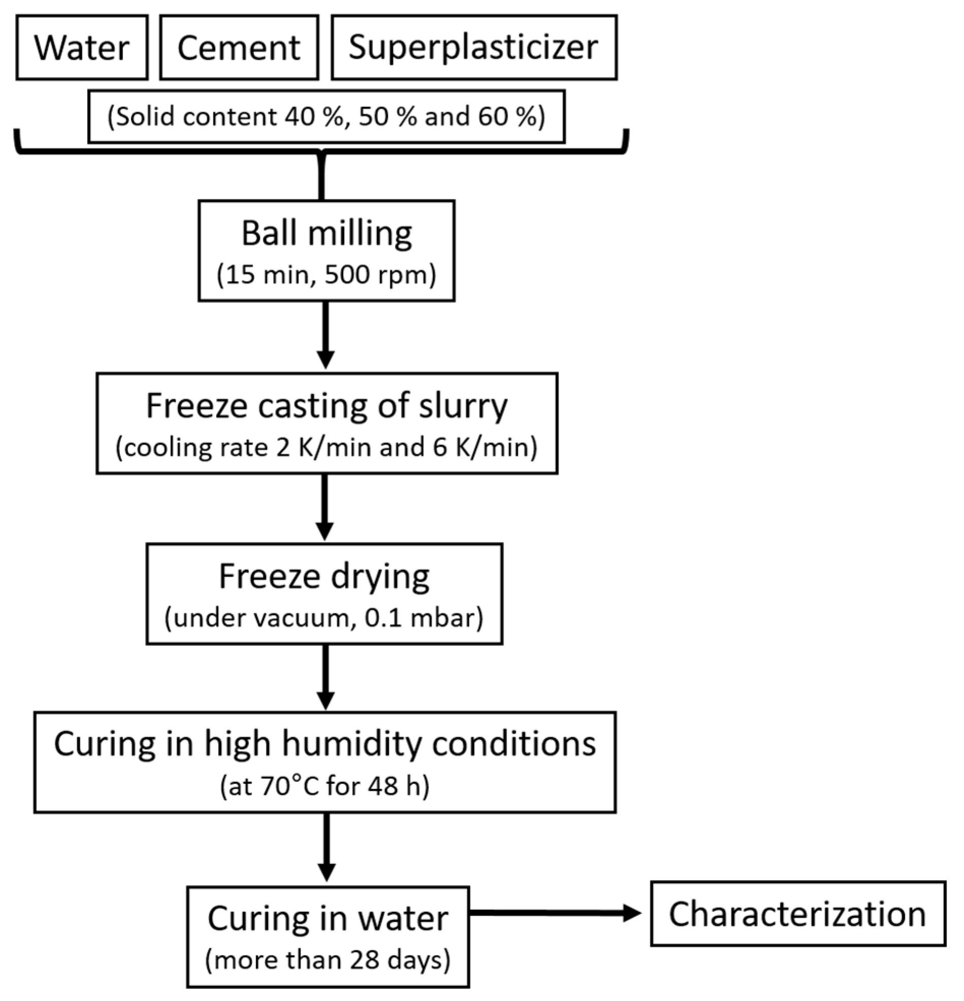
2.2. Fabrication of Membrane Supports
2.3. Characterization Methods
3. Results and Discussion
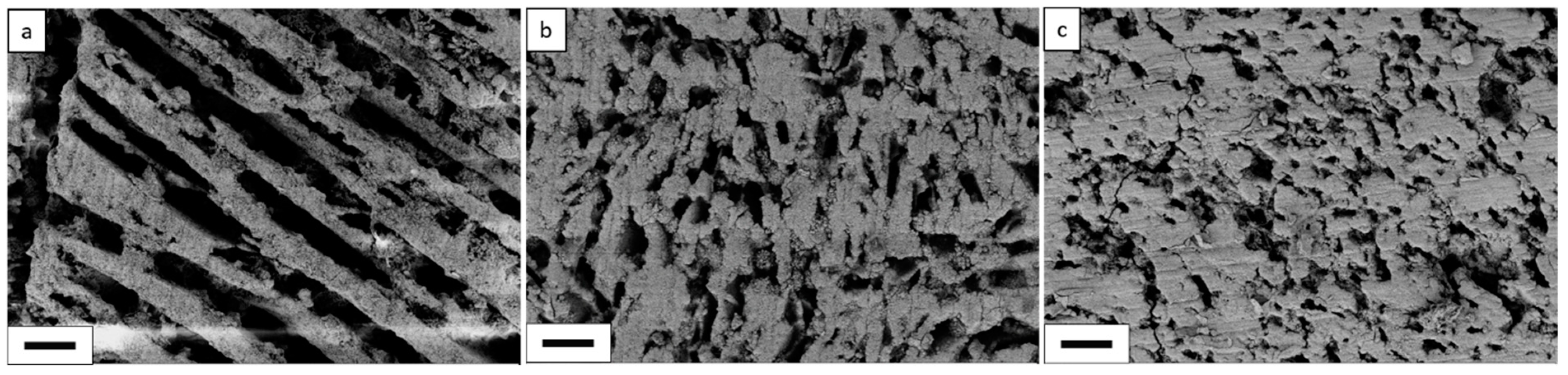
3.1. Microstructure
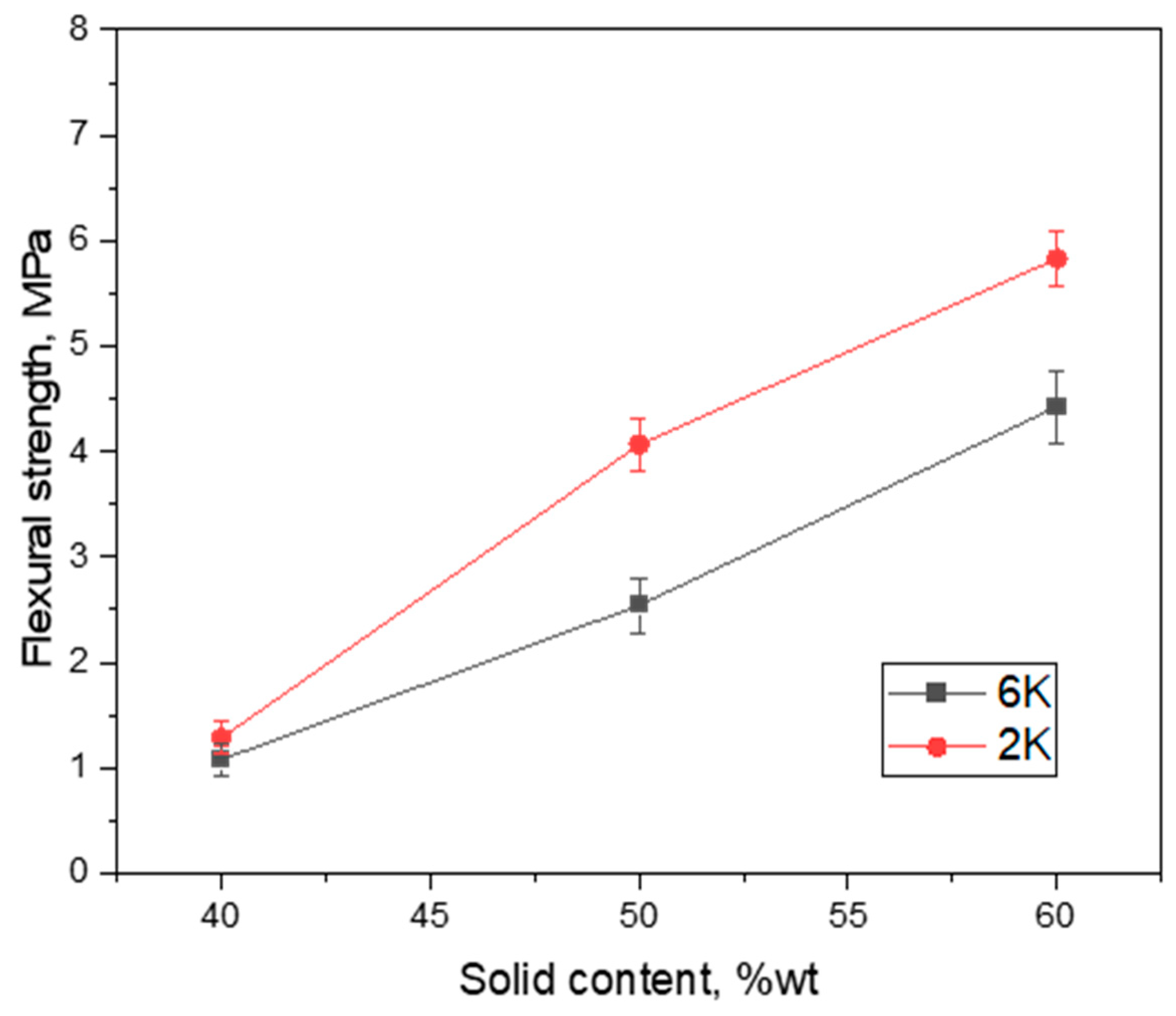
3.2. Mechanical Stability of Membranes
3.3. Permeability Performance
4. Conclusions
Author Contributions
Funding
Acknowledgments
Conflicts of Interest
References
- Baker, R.W. Membrane Technology and Applications, 2nd ed.; J. Wiley: Chichester, NY, USA, 2010; ISBN 9780470020388. [Google Scholar]
- Buekenhoudt, A. Stability of Porous Ceramic Membranes. In Inorganic Membranes: Synthesis, Characterization and Applications; Reyes Mallada, M.M., Ed.; Elsevier: Amsterdam, The Netherlands, 2008; pp. 1–31. ISBN 9780444530707. [Google Scholar]
- Cui, Z. Sintering Method for Ceramic Membrane Preparation. In Encyclopedia of Membranes; Drioli, E., Giorno, L., Eds.; Springer: Berlin/Heidelberg, Germany, 2015; pp. 1–2. ISBN 978-3-642-40872-4. [Google Scholar]
- Issaoui, M.; Limousy, L. Low-cost ceramic membranes: Synthesis, classifications, and applications. Comptes Rendus Chim. 2019, 22, 175–187. [Google Scholar] [CrossRef]
- Hubadillah, S.K.; Othman, M.H.D.; Matsuura, T.; Ismail, A.F.; Rahman, M.A.; Harun, Z.; Jaafar, J.; Nomura, M. Fabrications and applications of low cost ceramic membrane from kaolin: A comprehensive review. Ceram. Int. 2018, 44, 4538–4560. [Google Scholar] [CrossRef]
- Abdullayev, A.; Bekheet, M.F.; Hanaor, D.A.H.; Gurlo, A. Materials and Applications for Low-Cost Ceramic Membranes. Membranes 2019, 9, 105. [Google Scholar] [CrossRef] [PubMed]
- Hubadillah, S.K.; Othman, M.H.D.; Ismail, A.F.; Rahman, M.A.; Jaafar, J. A low cost hydrophobic kaolin hollow fiber membrane (h-KHFM) for arsenic removal from aqueous solution via direct contact membrane distillation. Sep. Purif. Technol. 2019, 214, 31–39. [Google Scholar] [CrossRef]
- Ge, J.C.; Kim, J.Y.; Yoon, S.K.; Choi, N.J. Fabrication of low-cost and high-performance coal fly ash nanofibrous membranes via electrospinning for the control of harmful substances. Fuel 2019, 237, 236–244. [Google Scholar] [CrossRef]
- Hubadillah, S.K.; Othman, M.H.D.; Ismail, A.F.; Rahman, M.A.; Jaafar, J.; Iwamoto, Y.; Honda, S.; Dzahir, M.I.H.M.; Yusop, M.Z.M. Fabrication of low cost, green silica based ceramic hollow fibre membrane prepared from waste rice husk for water filtration application. Ceram. Int. 2018, 44, 10498–10509. [Google Scholar] [CrossRef]
- Zou, D.; Qiu, M.; Chen, X.; Drioli, E.; Fan, Y. One step co-sintering process for low-cost fly ash based ceramic microfiltration membrane in oil-in-water emulsion treatment. Sep. Purif. Technol. 2019, 210, 511–520. [Google Scholar] [CrossRef]
- Fu, M.; Liu, J.; Dong, X.; Zhu, L.; Dong, Y.; Hampshire, S. Waste recycling of coal fly ash for design of highly porous whisker-structured mullite ceramic membranes. J. Eur. Ceram. Soc. 2019, 39, 5320–5331. [Google Scholar] [CrossRef]
- Dong, S.; Gao, X.; Ma, Z.; Wang, X.; Gao, C. Ice-templated porous silicate cement with hierarchical porosity. Mater. Lett. 2018, 217, 292–295. [Google Scholar] [CrossRef]
- Bye, G.C. Portland Cement. Composition, Production and Properties, 2nd ed.; Thomas Telford: London, UK, 1999; ISBN 0727727664. [Google Scholar]
- Bullard, J.W.; Jennings, H.M.; Livingston, R.A.; Nonat, A.; Scherer, G.W.; Schweitzer, J.S.; Scrivener, K.L.; Thomas, J.J. Mechanisms of cement hydration. Cem. Concr. Res. 2011, 41, 1208–1223. [Google Scholar] [CrossRef]
- Hover, K.C. The influence of water on the performance of concrete. Constr. Build. Mater. 2011, 25, 3003–3013. [Google Scholar] [CrossRef]
- Wang, Z.; Chen, Z.; Chang, J.; Shen, J.; Kang, J.; Yang, L.; Chen, Q. A novel cementitious microfiltration membrane: Mechanisms of pore formation and properties for water permeation. RSC Adv. 2015, 5, 99–108. [Google Scholar] [CrossRef]
- Dong, B.; Wang, F.; Abadikhah, H.; Hao, L.; Xu, X.; Khan, S.A.; Wang, G.; Agathopoulos, S. Simple Fabrication of Concrete with Remarkable Self-Cleaning Ability, Robust Superhydrophobicity, Tailored Porosity, and Highly Thermal and Sound Insulation. ACS Appl. Mater. Interfaces 2019, 11, 42801–42807. [Google Scholar] [CrossRef] [PubMed]
- Dong, B.; Yang, M.; Wang, F.; Wang, J.; Hao, L.; Xu, X.; Wang, G.; Agathopoulos, S. Production and characterization of durable self-cleaning and engineering porous Al2O3 /CaAl12O19 ceramic membranes. J. Am. Ceram. Soc. 2019, 102, 3879–3886. [Google Scholar] [CrossRef]
- Dong, S.; Wang, L.; Gao, X.; Zhu, W.; Wang, Z.; Ma, Z.; Gao, C. Freeze casting of novel porous silicate cement supports using tert-butyl alcohol-water binary crystals as template: Microstructure, strength and permeability. J. Membr. Sci. 2017, 541, 143–152. [Google Scholar] [CrossRef]
- Dong, S.; Zhu, W.; Gao, X.; Wang, Z.; Wang, L.; Wang, X.; Gao, C. Preparation of tubular hierarchically porous silicate cement compacts via a tert-butyl alcohol (TBA)-based freeze casting method. Chem. Eng. J. 2016, 295, 530–541. [Google Scholar] [CrossRef]
- Deville, S. Freeze-Casting of Porous Ceramics: A Review of Current Achievements and Issues. Adv. Eng. Mater. 2008, 10, 155–169. [Google Scholar] [CrossRef]
- Dyckerhoff. MIKRODUR® Microfine Cements. Available online: http://www.dyckerhoff-bohrtechnik.de/online/download.jsp?idDocument=5456&instance=5 (accessed on 30 March 2020).
- C21 Committee. Test Methods for Determination of Water Absorption and Associated Properties by Vacuum Method for Pressed Ceramic Tiles and Glass Tiles and Boil Method for Extruded Ceramic Tiles and Non-tile Fired Ceramic Whiteware Products; ASTM International: West Conshohocken, PA, USA, 2018. [Google Scholar]
- Bührer, M.; Stampanoni, M.; Rochet, X.; Büchi, F.; Eller, J.; Marone, F. High-numerical-aperture macroscope optics for time-resolved experiments. J. Synchrotron Radiat. 2019, 26, 1161–1172. [Google Scholar] [CrossRef]
- Paganin, D.; Mayo, S.C.; Gureyev, T.E.; Miller, P.R.; Wilkins, S.W. Simultaneous phase and amplitude extraction from a single defocused image of a homogeneous object. J. Microsc. 2002, 206, 33–40. [Google Scholar] [CrossRef]
- Marone, F.; Stampanoni, M. Regridding reconstruction algorithm for real-time tomographic imaging. J. Synchrotron Radiat. 2012, 19, 1029–1037. [Google Scholar] [CrossRef]
- Zou, Y.; Gaudillere, C.; Escribano, J.E.; Serra, J.M.; Malzbender, J. Microstructure, mechanical behavior and flow resistance of freeze-cast porous 3YSZ substrates for membrane applications. J. Eur. Ceram. Soc. 2017, 37, 3167–3176. [Google Scholar] [CrossRef]
- C28 Committee. Test Method for Monotonic Equibiaxial Flexural Strength of Advanced Ceramics at Ambient Temperature; ASTM International: West Conshohocken, PA, USA, 2015. [Google Scholar]
- Deville, S.; Adrien, J.; Maire, E.; Scheel, M.; Di Michiel, M. Time-lapse, three-dimensional in situ imaging of ice crystal growth in a colloidal silica suspension. Acta Mater. 2013, 61, 2077–2086. [Google Scholar] [CrossRef]
- Nagashima, K.; Furukawa, Y. Nonequilibrium effect of anisotropic interface kinetics on the directional growth of ice crystals. J. Cryst. Growth 1997, 171, 577–585. [Google Scholar] [CrossRef]
- Waschkies, T.; Oberacker, R.; Hoffmann, M. Investigation of structure formation during freeze-casting from very slow to very fast solidification velocities. Acta Mater. 2011, 59, 5135–5145. [Google Scholar] [CrossRef]
- Li, W.L.; Lu, K.; Walz, J.Y. Freeze casting of porous materials: Review of critical factors in microstructure evolution. Int. Mater. Rev. 2012, 57, 37–60. [Google Scholar] [CrossRef]
- Deville, S.; Saiz, E.P.; Tomsia, A. Ice-templated porous alumina structures. Acta Mater. 2007, 55, 1965–1974. [Google Scholar] [CrossRef]
- Deville, S. Ice-Templating, Freeze-Casting: A Practical Guide to Get Started. In Freezing Colloids: Observations, Principles, Control, and Use; Deville, S., Ed.; Springer International Publishing: Cham, Switzerland, 2017; pp. 549–592. ISBN 978-3-319-50513-8. [Google Scholar]
- Seuba, J.; Deville, S.; Guizard, C.; Stevenson, A.J. Mechanical properties and failure behavior of unidirectional porous ceramics. Sci. Rep. 2016, 6, 24326. [Google Scholar] [CrossRef]
- Lee, J.H.; Choi, H.J.; Yoon, S.Y.; Kim, B.K.; Park, H.C. Porous mullite ceramics derived from coal fly ash using a freeze-gel casting/polymer sponge technique. J. Porous Mater. 2013, 20, 219–226. [Google Scholar] [CrossRef]
- Liu, R.; Yuan, J.; Wang, C.-A. A novel way to fabricate tubular porous mullite membrane supports by TBA-based freezing casting method. J. Eur. Ceram. Soc. 2013, 33, 3249–3256. [Google Scholar] [CrossRef]
- Singh, G.; Bulasara, V.K. Preparation of low-cost microfiltration membranes from fly ash. Desalin. Water Treat. 2013, 1–9. [Google Scholar] [CrossRef]
- Jana, S.; Purkait, M.K.; Mohanty, K. Preparation and characterization of low-cost ceramic microfiltration membranes for the removal of chromate from aqueous solutions. Appl. Clay Sci. 2010, 47, 317–324. [Google Scholar] [CrossRef]
- Bouzerara, F.; Harabi, A.; Condom, S. Porous ceramic membranes prepared from kaolin. Desalin. Water Treat. 2009, 12, 415–419. [Google Scholar] [CrossRef]
- Masmoudi, S.; Larbot, A.; Feki, H.E.; Amar, R.B. Elaboration and characterisation of apatite based mineral supports for microfiltration and ultrafiltration membranes. Ceram. Int. 2007, 33, 337–344. [Google Scholar] [CrossRef]
- Kouras, N.; Harabi, A.; Bouzerara, F.; Foughali, L.; Policicchio, A.; Stelitano, S.; Galiano, F.; Figoli, A. Macro-porous ceramic supports for membranes prepared from quartz sand and calcite mixtures. J. Eur. Ceram. Soc. 2017, 37, 3159–3165. [Google Scholar] [CrossRef]
- Elomari, H.; Achiou, B.; Ouammou, M.; Albizane, A.; Bennazha, J.; Alami Younssi, S.; Elamrani, I. Elaboration and characterization of flat membrane supports from Moroccan clays. Application for the treatment of wastewater. Desalin. Water Treat. 2016, 57, 20298–20306. [Google Scholar] [CrossRef]
- Hristov, P.; Yoleva, A.; Djambazov, S.; Chukovska, I.; Dimitrov, D. Preparation and characterization of porous ceramic membranes for micro-filtration from natural zeolite. J. Univ. Chem. Technol. Metall. 2012, 47, 476–480. [Google Scholar]
- Ivanets, A.I.; Rat’ko, A.I.; Azarova, T.A.; Azarov, S.M.; Al-Khowaiter, S.H.; Al-Harbi, O.; Shemchonok, S.V.; Dobysh, V.A.; Tarasevich, V.A.; Agabekov, V.E.; et al. Preparation and properties of microfiltration membranes based on natural crystalline SiO2. Ceram. Int. 2014, 40, 12343–12351. [Google Scholar] [CrossRef]
- Papatzani, S. Effect of nanosilica and montmorillonite nanoclay particles on cement hydration and microstructure. Mater. Sci. Technol. 2016, 32, 138–153. [Google Scholar] [CrossRef]


| Sample | Solid Content of Slurry *, wt% | Cement, g | Water, g | Superplasticizer, g | Freezing Rate, K/min |
|---|---|---|---|---|---|
| 2K40 | 40 | 4.0 | 6.0 | 0.04 | 2 |
| 2K50 | 50 | 5.0 | 5.0 | 0.1 | 2 |
| 2K60 | 60 | 6.0 | 4.0 | 0.12 | 2 |
| 6K40 | 40 | 4.0 | 6.0 | 0.04 | 6 |
| 6K50 | 50 | 5.0 | 5.0 | 0.1 | 6 |
| 6K60 | 60 | 6.0 | 4.0 | 0.12 | 6 |
| Material | Preparation Method | Sintering Temperature, °C | Porosity, % | Mechanical Stability, MPa* | Reference |
|---|---|---|---|---|---|
| Cement | Freeze casting | No sintering | 48–73 | 1.3–5.8 (F) | This work |
| Cement | Freeze casting | No sintering | 48–62 | 10.7–16.6 (C) | [12] |
| Cement | Freeze casting | No sintering | 57–69 | 9.7–15.2 (C) | [20] |
| Cement | Freeze casting | No sintering | 50–58 | 1.1–12.5 (C) | [19] |
| Fly ash + alumina | Freeze casting | 1600 | 62 | 45 (C) | [36] |
| Mullite | Freeze casting | 1550 | 66–77 | 23–33 (C) | [37] |
| Fly ash | Paste casting | 800–1000 | 35–40 | 8–20 (F) | [38] |
| Kaolin + additives | Paste casting | 850–1000 | 33–42 | 3-8 (F) | [39] |
| Kaolin | Extrusion | 1000–1250 | 46–60 | 4–24 (F) | [40] |
| Apatite | Extrusion | 1150 | 40 | 15 (F) | [41] |
| Kaolin + Dolomite | Pressing | 1375 | 42–55 | 8–18 (F) | [42] |
| Moroccan Clay | Pressing | 950 | 40 | 14 (F) | [43] |
| Natural zeolite | Pressing | 800-900 | 13–38 | 4.5–6.0 (F) | [44] |
| Quartz sand | Pressing | 850 | 23–35 | 15–39 (C) | [45] |
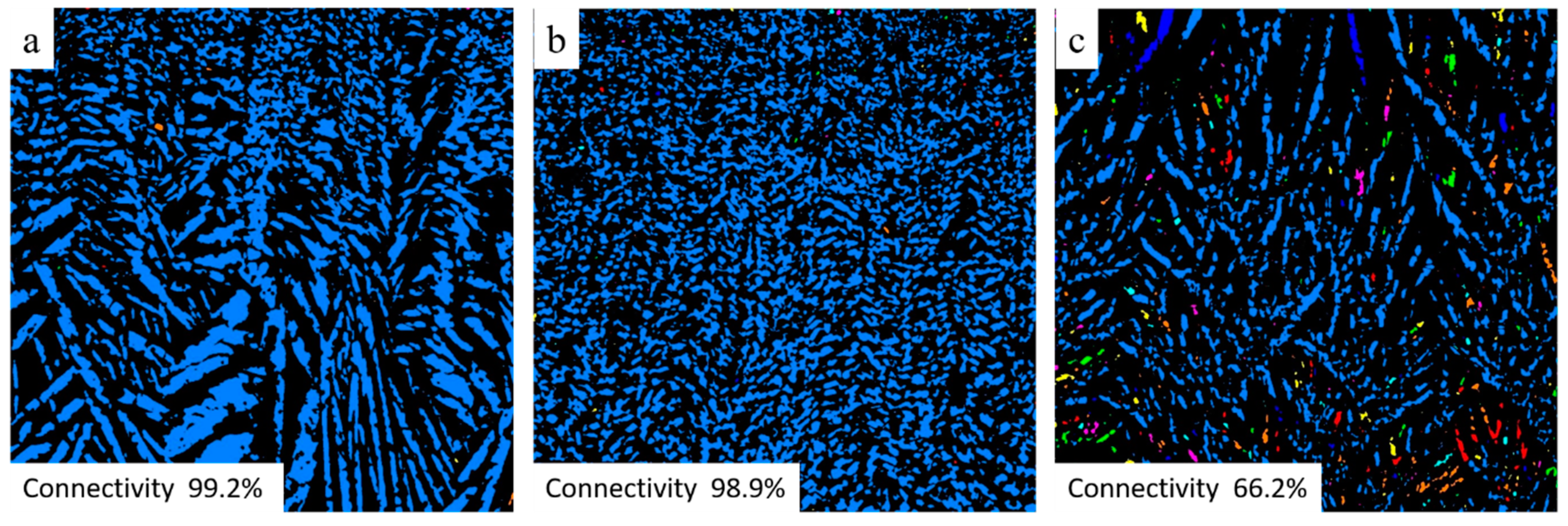
| Sample | Trans-Membrane Pressure, bar | Pure Water Flux, L/(h·m2) | Porosity by Archimedes Method (open porosity), % | Porosity by µCT (pores > 5 µm), % | Fraction of Connected Pores by µCT, % |
|---|---|---|---|---|---|
| 6K50 | 0.5 | 80 ± 5 | 60.1 ± 0.5 | 14 | 66.2 |
| 2K50 | 0.5 | 181 ± 7 | 62.3 ± 0.2 | 35 | 99.2 |
| 2K60 | 0.5 | 135 ± 5 | 50.1 ± 0.3 | 31 | 98.9 |
© 2020 by the authors. Licensee MDPI, Basel, Switzerland. This article is an open access article distributed under the terms and conditions of the Creative Commons Attribution (CC BY) license (http://creativecommons.org/licenses/by/4.0/).
Share and Cite
Abdullayev, A.; Kamm, P.H.; Bekheet, M.F.; Gurlo, A. Fabrication and Characterization of Ice Templated Membrane Supports from Portland Cement. Membranes 2020, 10, 93. https://doi.org/10.3390/membranes10050093
Abdullayev A, Kamm PH, Bekheet MF, Gurlo A. Fabrication and Characterization of Ice Templated Membrane Supports from Portland Cement. Membranes. 2020; 10(5):93. https://doi.org/10.3390/membranes10050093
Chicago/Turabian StyleAbdullayev, Amanmyrat, Paul H. Kamm, Maged F. Bekheet, and Aleksander Gurlo. 2020. "Fabrication and Characterization of Ice Templated Membrane Supports from Portland Cement" Membranes 10, no. 5: 93. https://doi.org/10.3390/membranes10050093
APA StyleAbdullayev, A., Kamm, P. H., Bekheet, M. F., & Gurlo, A. (2020). Fabrication and Characterization of Ice Templated Membrane Supports from Portland Cement. Membranes, 10(5), 93. https://doi.org/10.3390/membranes10050093