Recent Progress in the Engineering of Polymeric Membranes for CO2 Capture from Flue Gas


Abstract
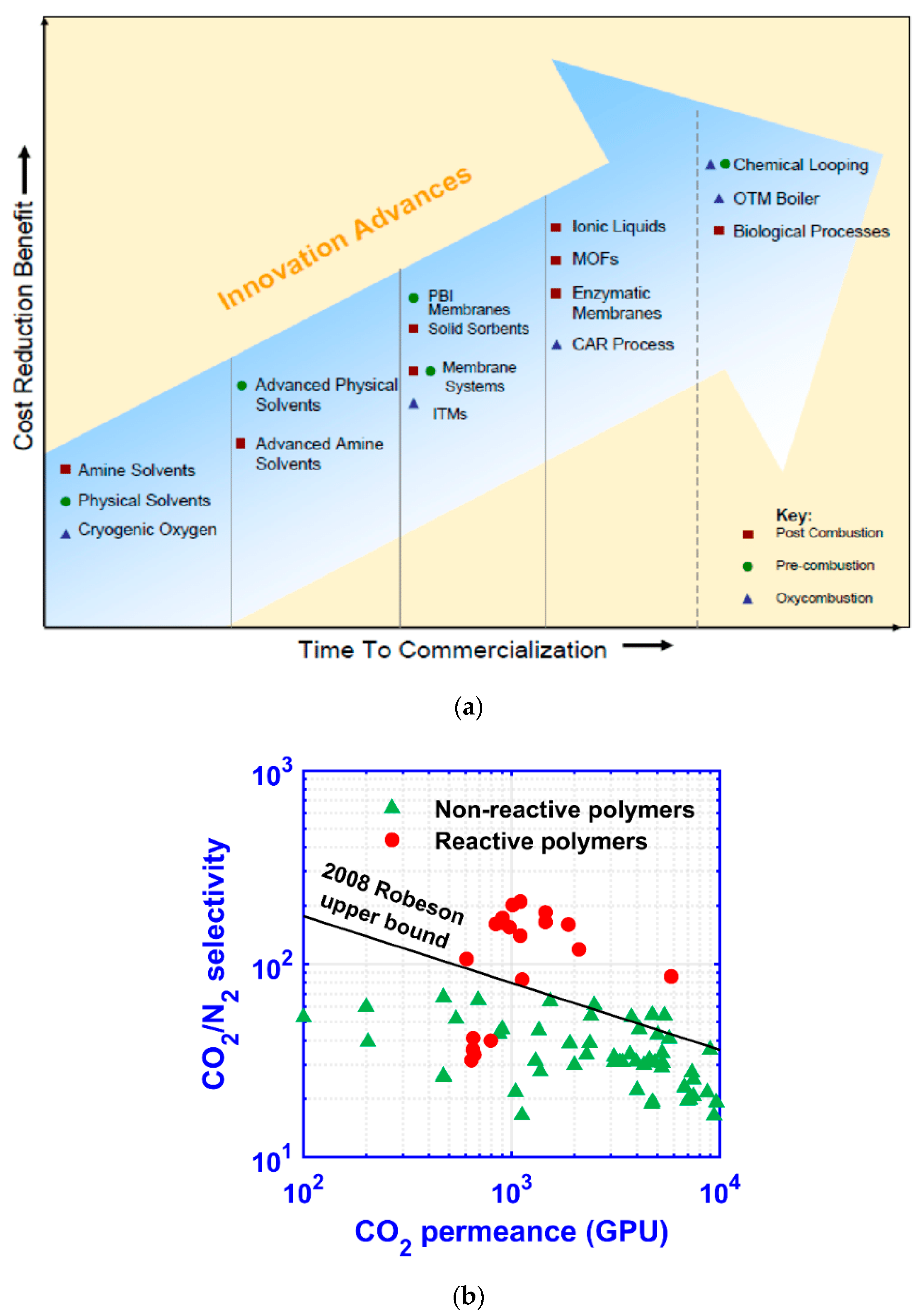
1. Introduction
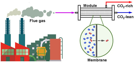
2. Membrane Process
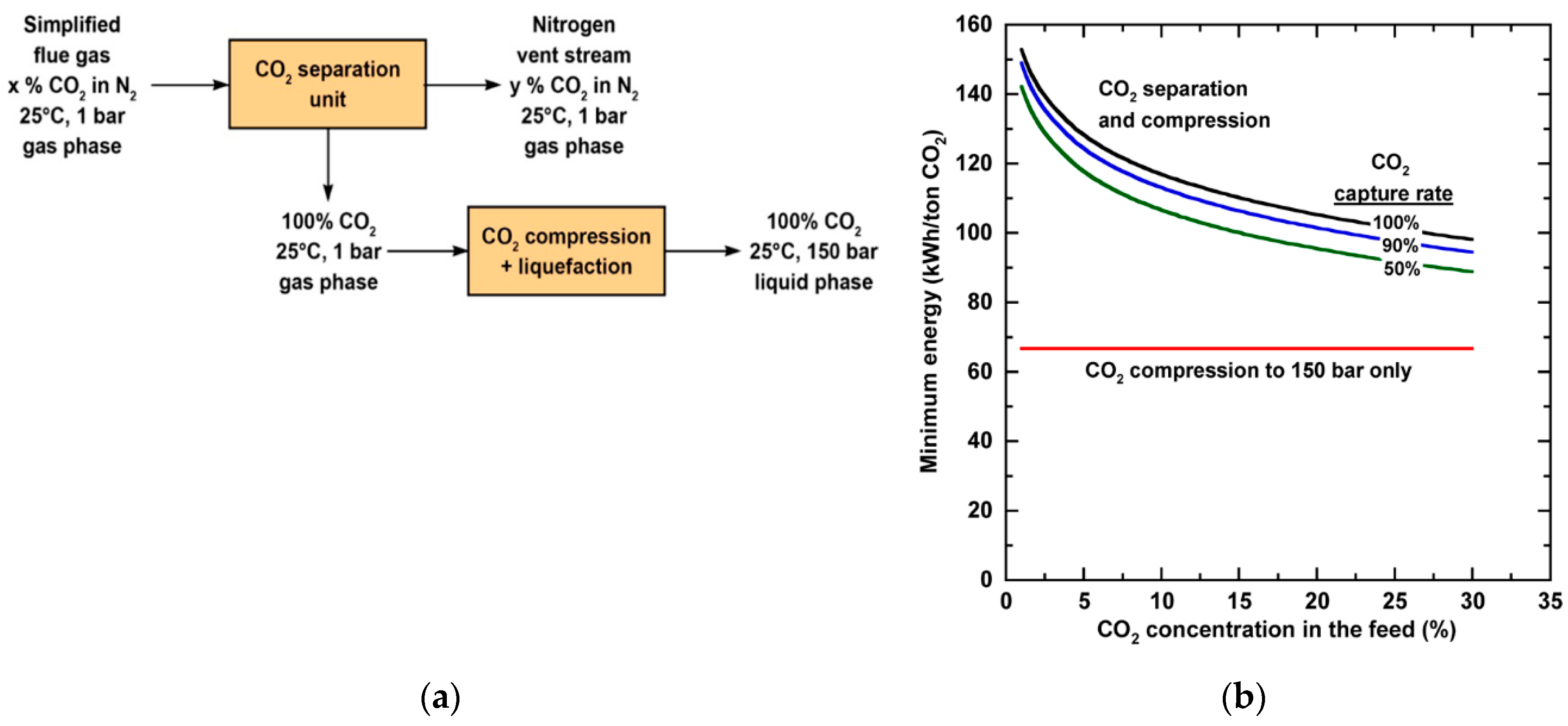
2.1. Minimum Energy for Separation
2.2. Process Synthesis
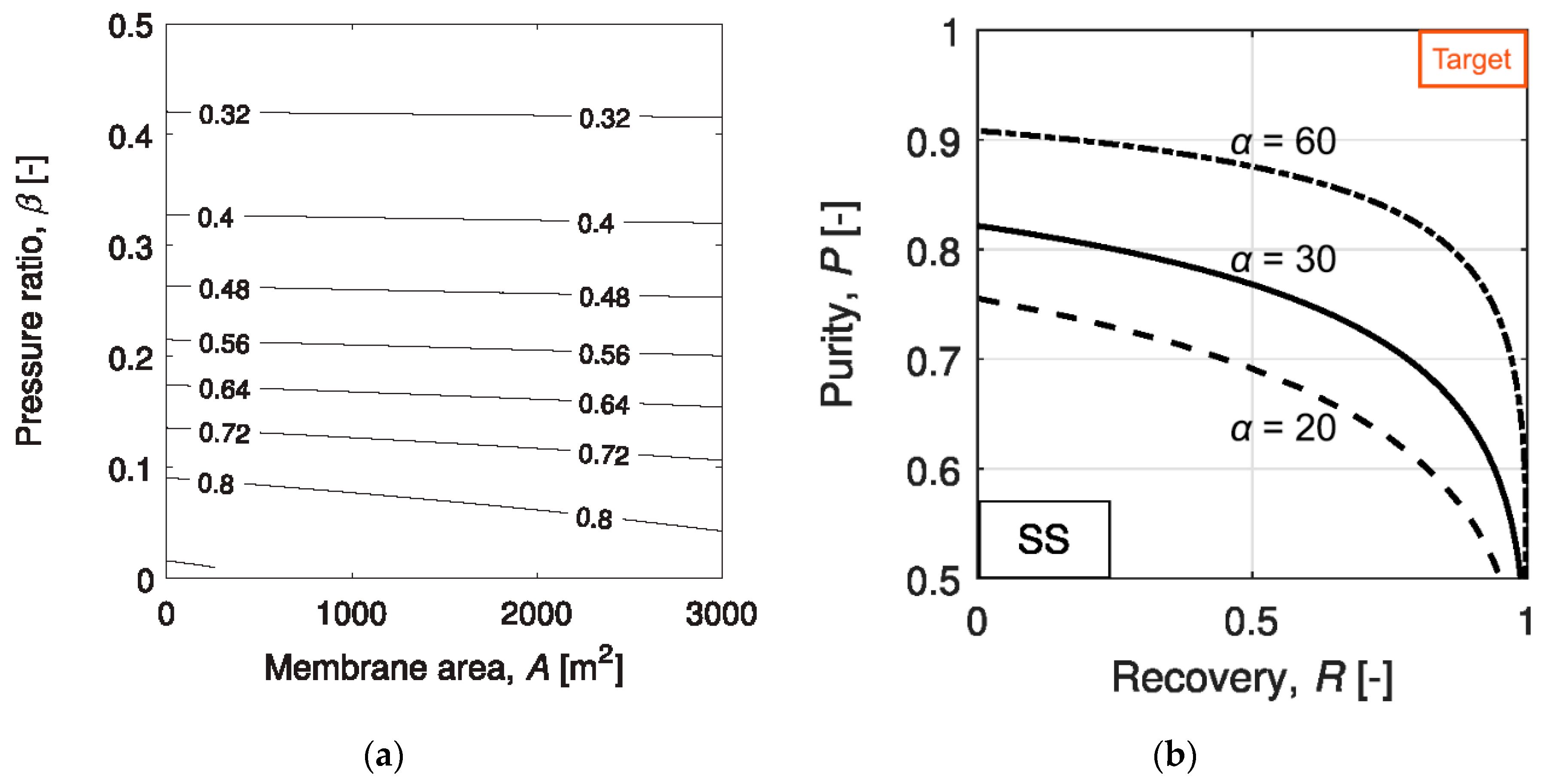
2.2.1. Single-Stage Process
2.2.2. Multi-Stage Processes
2.2.3. Processes for Natural Gas-Derived Flue Gas
3. Membrane Scale-Up, Modular Fabrication, and Field Tests
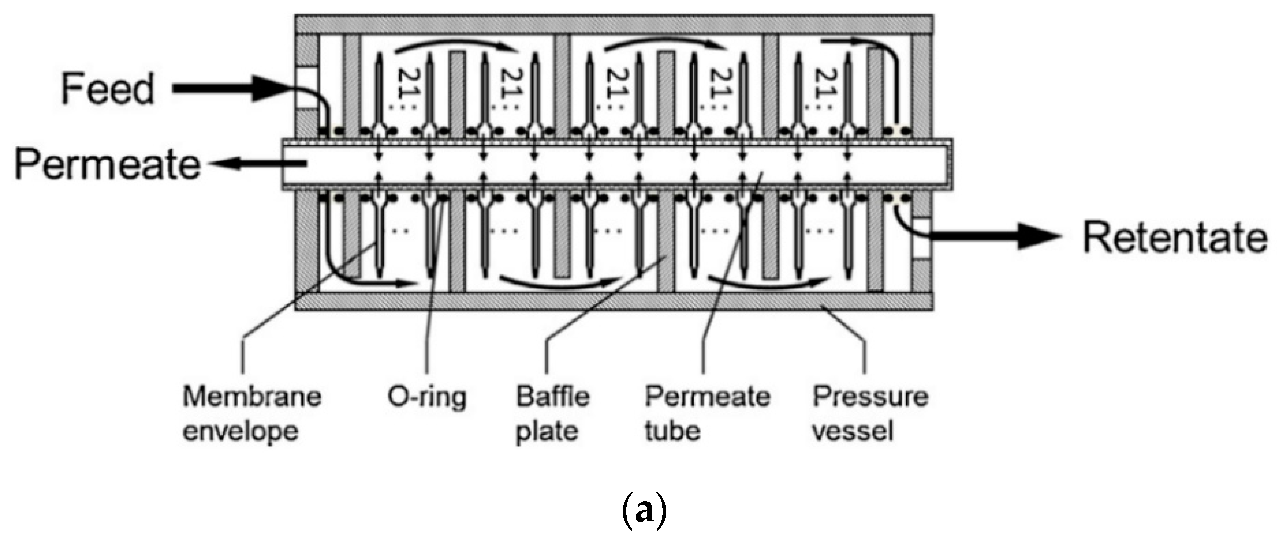
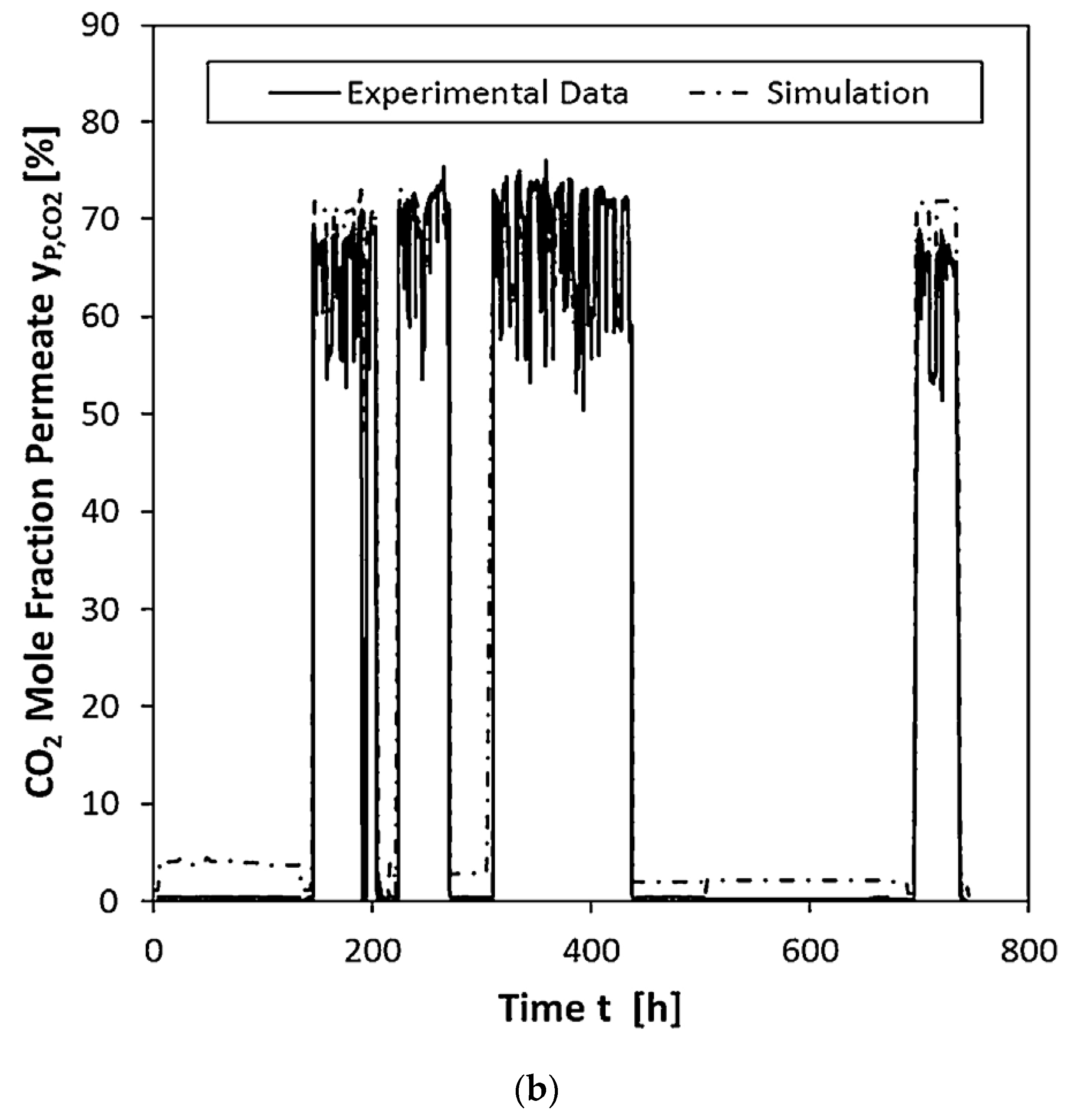
3.1. Plate-and-Frame Modules
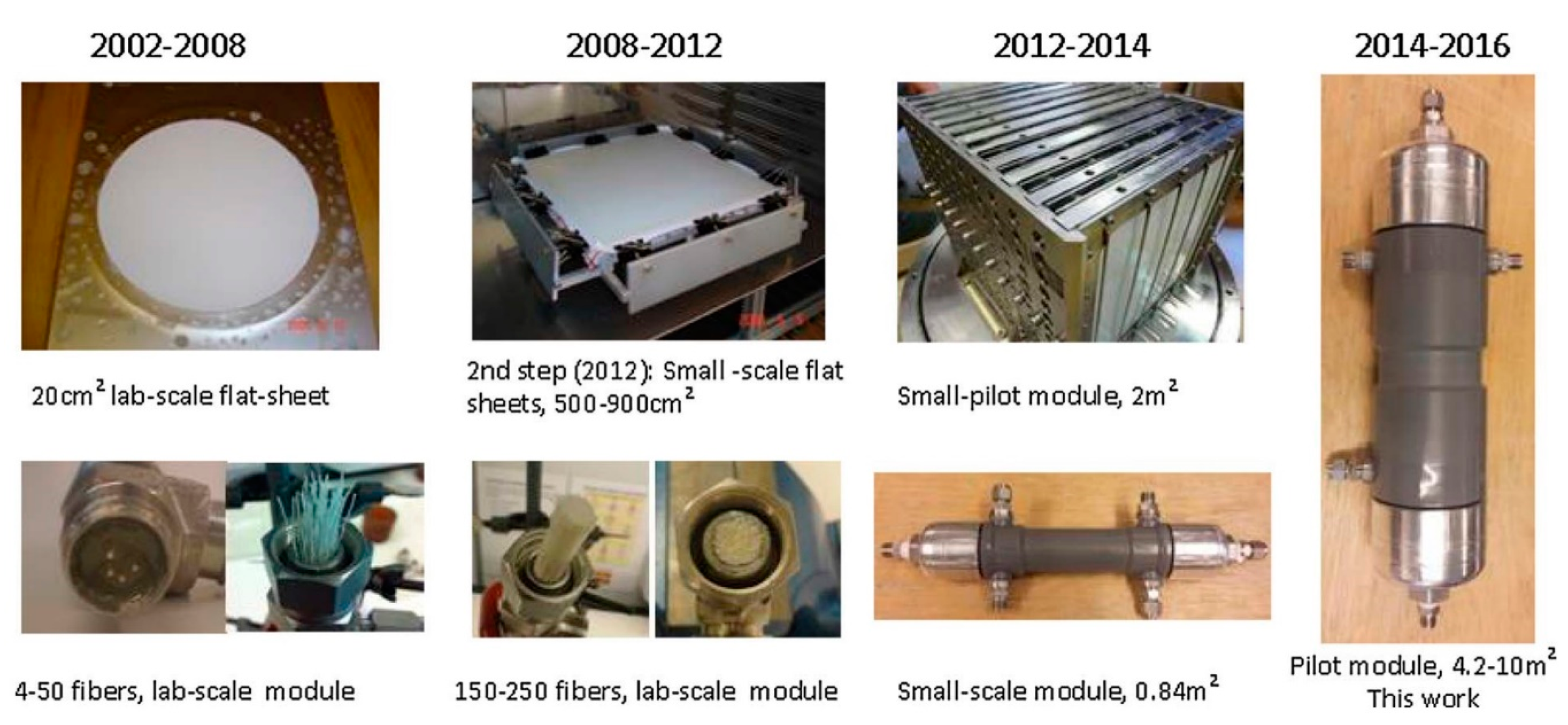
3.2. Hollow-Fiber Modules
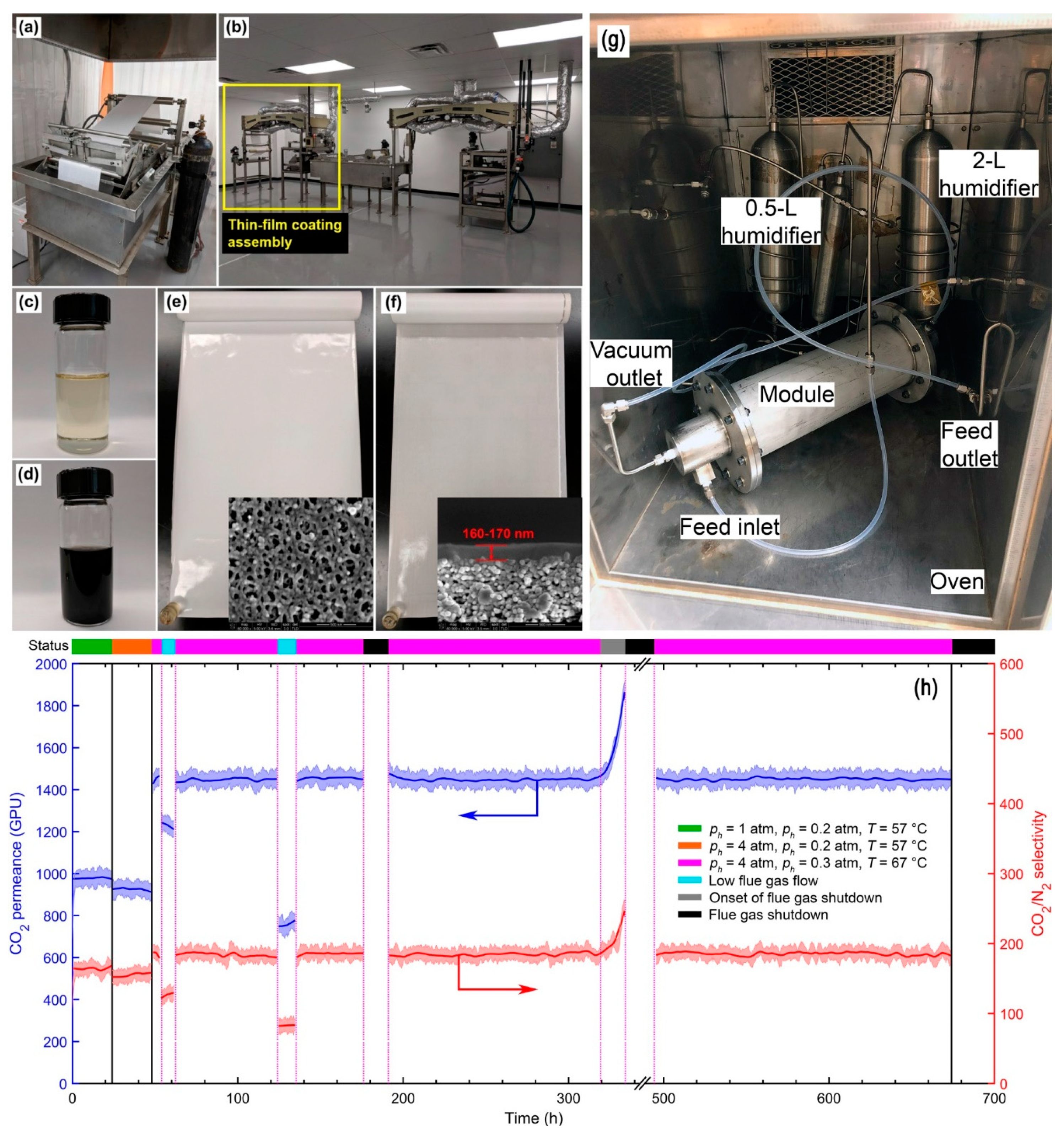
3.3. Spiral-Wound Modules
4. Conclusions
- (1)
- The CO2 capture from a dilute source such as flue gas is intrinsically energy-intensive, showcasing low-energy consumption benefits of membrane process. The assignment of proper transmembrane driving force is the key to balance the second-law efficiency and the footprint of a membrane system.
- (2)
- Limited by the membrane selectivity and practical feed-to-permeate pressure ratio, a single-stage membrane process can only partially capture the CO2. For a higher CO2 recovery, a multi-stage cascade design is mandatory.
- (3)
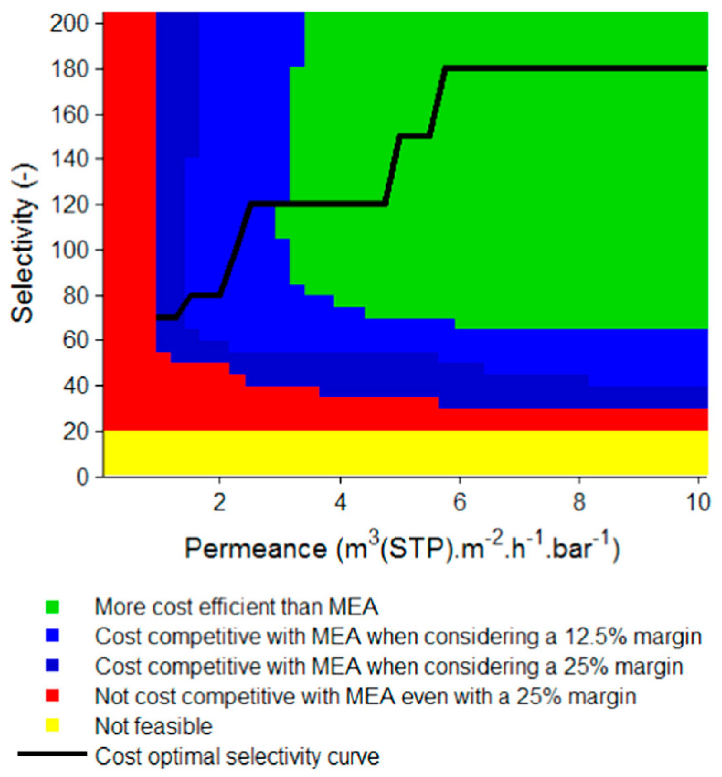
- Enriching and stripping cascades are both suitable for 90% CO2 recovery, provided that sophisticated recycling streams are designed in the processes to enhance the CO2 flux. In order to achieve a >95% CO2 purity, a CO2/N2 selectivity greater than 50 is needed to make the process feasible. However, a higher selectivity (e.g., >100) is generally required for an optimized membrane-alone process.
- (4)
- HF and SW modules are the preferred modular configurations due to their higher packing density and ease of manufacturing. Although less studied, PF modules also have applications in post-combustion carbon capture, especially in pre-pilot studies and situations where a high-pressure drop is unaffordable.
- (5)
- The actual flue gases are invasive to the membrane operation. The frequently encountered challenges include the fouling by the particulate matter, the chemical degradation caused by SOx and NOx, heavy metal deposition, and water-induced plasticization. These factors should be considered during the membrane development. In addition, flue gas pretreatment should be emphasized prior to a field trial.
Author Contributions
Funding
Acknowledgments
Conflicts of Interest
References
- U.S. Energy Information Administration. Annual Energy Outlook; U.S. Energy Information Administration: Washington, DC, USA, 29 January 2020.
- Miller, R.L.; Schmidt, G.A.; Nazarenko, L.S.; Tausnev, N.; Bauer, S.E.; DelGenio, A.D.; Kelley, M.; Lo, K.K.; Ruedy, R.; Shindell, D.T. CMIP5 historical simulations (1850–2012) with GISS ModelE2. J. Adv. Model. Earth Syst. 2014, 6, 441–477. [Google Scholar] [CrossRef]
- Andreoni, V.; Galmarini, S. Drivers in CO2 emissions variation: A decomposition analysis for 33 world countries. Energy 2016, 103, 27–37. [Google Scholar] [CrossRef]
- Allen, M.; Babiker, M.; Chen, Y.; de Coninck, H.; Conors, S. Global Warming of 1.5 °C: An IPCC Special Report on the Impacts of Global Warming of 1.5 °C above Pre-industrial Levels and Related Global Greenhouse Gas Emission Pathways, in the Context of Strengthening the Global Response to the Threat of Climate Change, Sustainable Development, and Efforts to Eradicate Poverty; Intergovernmental Panel on Climate Change: Incheon, Korea, 2018. [Google Scholar]
- Barteau, M.A.; Dunn, J.; Allen, D.; Burkart, M.D.; Gaffney, A.M.; Gupta, R.; Hazari, N.; Kanan, M.; Kenis, P.; Klee, H. Gaseous carbon waste streams utilization: Status and research needs. AGUFM 2018, 2018, GC41A-03. [Google Scholar]
- Black, J. Cost and Performance Baseline for Fossil Energy Plants Volume 1: Bituminous Coal and Natural Gas to Electricity, 2nd ed.; Final report; National Energy Technology Laboratory: Irving, TX, USA, November 2010.
- Figueroa, J.D.; Fout, T.; Plasynski, S.; McIlvried, H.; Srivastava, R.D. Advances in CO2 capture technology—The U.S. Department of Energy’s carbon sequestration program. Int. J. Greenh. Gas Con. 2008, 2, 9–20. [Google Scholar] [CrossRef]
- Accelerating Breakthrough Innovation in Carbon Capture, Utilization, and Storage. In Proceedings of the Report of the Mission Innovation Carbon Capture, Utilization, and Storage Experts’ Workshop, Houston, TX, USA, 26–28 September 2017; Available online: https://www.energy.gov/fe/downloads/accelerating-breakthrough-innovation-carbon-capture-utilization-and-storage (accessed on 31 October 2020).
- Han, Y.; Ho, W.S.W. Recent developments on polymeric membranes for CO2 capture from flue gas. J. Polym. Eng. 2020, 40, 529–542. [Google Scholar] [CrossRef]
- Han, Y.; Ho, W.S.W. Recent advances in polymeric membranes for CO2 capture. Chin. J. Chem. Eng. 2018, 26, 2238–2254. [Google Scholar] [CrossRef]
- Du, N.; Park, H.B.; Dal-Cin, M.M.; Guiver, M.D. Advances in high permeability polymeric membrane materials for CO2 separations. Energy Environ. Sci. 2012, 5, 7306–7322. [Google Scholar] [CrossRef]
- Robeson, L.M. The upper bound revisited. J. Membr. Sci. 2008, 320, 390–400. [Google Scholar] [CrossRef]
- McGlashan, N.; Marquis, A. Availability analysis of post-combustion carbon capture systems: Minimum work input. Proc. Inst. Mech. Eng. C J. Mech. Eng. Sci. 2007, 221, 1057–1065. [Google Scholar] [CrossRef]
- Merkel, T.C.; Wei, X.; He, Z.; White, L.S.; Wijmans, J.; Baker, R.W. Selective exhaust gas recycle with membranes for CO2 capture from natural gas combined cycle power plants. Ind. Eng. Chem. Res. 2012, 52, 1150–1159. [Google Scholar] [CrossRef]
- Herzog, H.; Meldon, J.; Hatton, A. Advanced post-combustion CO2 capture. Clean Air Task Force 2009, 1, 39. [Google Scholar]
- Bhown, A.S.; Freeman, B.C. Analysis and status of post-combustion carbon dioxide capture technologies. Environ. Sci. Technol. 2011, 45, 8624–8632. [Google Scholar] [CrossRef] [PubMed]
- House, K.Z.; Baclig, A.C.; Ranjan, M.; van Nierop, E.A.; Wilcox, J.; Herzog, H.J. Economic and energetic analysis of capturing CO2 from ambient air. Proc. Natl. Acad. Sci. USA 2011, 108, 20428–20433. [Google Scholar] [CrossRef] [PubMed]
- Ho, W.S.W.; Sirkar, K.K. Membrane Handbook, reprint ed.; Kluwer Academic Publishers: Boston, MA, USA, 2001. [Google Scholar]
- Huang, Y.; Merkel, T.C.; Baker, R.W. Pressure ratio and its impact on membrane gas separation processes. J. Membr. Sci. 2014, 463, 33–40. [Google Scholar] [CrossRef]
- Favre, E. Carbon dioxide recovery from post-combustion processes: Can gas permeation membranes compete with absorption? J. Membr. Sci. 2007, 294, 50–59. [Google Scholar] [CrossRef]
- Gabrielli, P.; Gazzani, M.; Mazzotti, M. On the optimal design of membrane-based gas separation processes. J. Membr. Sci. 2017, 526, 118–130. [Google Scholar] [CrossRef]
- Zhai, H.; Rubin, E.S. Techno-economic assessment of polymer membrane systems for postcombustion carbon capture at coal-fired power plants. Environ. Sci. Technol. 2013, 47, 3006–3014. [Google Scholar] [CrossRef]
- Khalilpour, R.; Abbas, A.; Lai, Z.; Pinnau, I. Modeling and parametric analysis of hollow fiber membrane system for carbon capture from multicomponent flue gas. AIChE J. 2012, 58, 1550–1561. [Google Scholar] [CrossRef]
- Yang, D.; Wang, Z.; Wang, J.; Wang, S. Potential of two-stage membrane system with recycle stream for CO2 capture from postcombustion gas. Energy Fuels 2009, 23, 4755–4762. [Google Scholar] [CrossRef]
- Zhao, L.; Menzer, R.; Riensche, E.; Blum, L.; Stolten, D. Concepts and investment cost analyses of multi-stage membrane systems used in post-combustion processes. Energy Procedia 2009, 1, 269–278. [Google Scholar] [CrossRef][Green Version]
- Hussain, A.; Hägg, M.-B. A feasibility study of CO2 capture from flue gas by a facilitated transport membrane. J. Membr. Sci. 2010, 359, 140–148. [Google Scholar] [CrossRef]
- Zhao, L.; Riensche, E.; Blum, L.; Stolten, D. How gas separation membrane competes with chemical absorption in post-combustion capture. Energy Procedia 2011, 4, 629–636. [Google Scholar] [CrossRef]
- Franz, J.; Schiebahn, S.; Zhao, L.; Riensche, E.; Scherer, V.; Stolten, D. Investigating the influence of sweep gas on CO2/N2 membranes for post-combustion capture. Int. J. Greenh. Gas Con. 2013, 13, 180–190. [Google Scholar] [CrossRef]
- He, X.; Fu, C.; Hägg, M.-B. Membrane system design and process feasibility analysis for CO2 capture from flue gas with a fixed-site-carrier membrane. Chem. Eng. J. 2015, 268, 1–9. [Google Scholar] [CrossRef]
- Pfister, M.; Belaissaoui, B.; Favre, E. Membrane gas separation processes from wet postcombustion flue gases for carbon capture and use: A critical reassessment. Ind. Eng. Chem. Res. 2017, 56, 591–602. [Google Scholar] [CrossRef]
- Zhao, L.; Riensche, E.; Blum, L.; Stolten, D. Multi-stage gas separation membrane processes used in post-combustion capture: Energetic and economic analyses. J. Membr. Sci. 2010, 359, 160–172. [Google Scholar] [CrossRef]
- Bocciardo, D.; Ferrari, M.-C.; Brandani, S. Modelling and multi-stage design of membrane processes applied to carbon capture in coal-fired power plants. Energy Procedia 2013, 37, 932–940. [Google Scholar] [CrossRef][Green Version]
- Roussanaly, S.; Anantharaman, R.; Lindqvist, K.; Zhai, H.; Rubin, E. Membrane properties required for post-combustion CO2 capture at coal-fired power plants. J. Membr. Sci. 2016, 511, 250–264. [Google Scholar] [CrossRef]
- Xu, J.; Wang, Z.; Qiao, Z.; Wu, H.; Dong, S.; Zhao, S.; Wang, J. Post-combustion CO2 capture with membrane process: Practical membrane performance and appropriate pressure. J. Membr. Sci. 2019, 581, 195–213. [Google Scholar] [CrossRef]
- White, L.S.; Wei, X.; Pande, S.; Wu, T.; Merkel, T.C. Extended flue gas trials with a membrane-based pilot plant at a one-ton-per-day carbon capture rate. J. Membr. Sci. 2015, 496, 48–57. [Google Scholar] [CrossRef]
- Vakharia, V.; Salim, W.; Wu, D.; Han, Y.; Chen, Y.; Zhao, L.; Ho, W.S.W. Scale-up of amine-containing thin-film composite membranes for CO2 capture from flue gas. J. Membr. Sci. 2018, 555, 379–387. [Google Scholar] [CrossRef]
- Han, Y.; Ho, W.S.W. Design of amine-containing CO2-selective membrane process for carbon capture from flue gas. Ind. Eng. Chem. Res. 2020, 59, 5340–5350. [Google Scholar] [CrossRef]
- Han, Y.; Salim, W.; Chen, K.K.; Wu, D.; Ho, W.S.W. Field trial of spiral-wound facilitated transport membrane module for CO2 capture from flue gas. J. Membr. Sci. 2019, 575, 242–251. [Google Scholar] [CrossRef]
- Han, Y.; Wu, D.; Ho, W.S.W. Simultaneous effects of temperature and vacuum and feed pressures on facilitated transport membrane for CO2/N2 separation. J. Membr. Sci. 2019, 573, 476–484. [Google Scholar] [CrossRef]
- Han, Y.; Wu, D.; Ho, W.S.W. Nanotube-reinforced facilitated transport membrane for CO2/N2 separation with vacuum operation. J. Membr. Sci. 2018, 567, 261–271. [Google Scholar] [CrossRef]
- Merkel, T.C.; Lin, H.; Wei, X.; Baker, R. Power plant post-combustion carbon dioxide capture: An opportunity for membranes. J. Membr. Sci. 2010, 359, 126–139. [Google Scholar] [CrossRef]
- Ramasubramanian, K.; Verweij, H.; Ho, W.S.W. Membrane processes for carbon capture from coal-fired power plant flue gas: A modeling and cost study. J. Membr. Sci. 2012, 421, 299–310. [Google Scholar] [CrossRef]
- Swisher, J.A.; Bhown, A.S. Analysis and optimal design of membrane-based CO2 capture processes for coal and natural gas-derived flue gas. Energy Procedia 2014, 63, 225–234. [Google Scholar] [CrossRef]
- Bolland, O.; Mathieu, P. Comparison of two CO2 removal options in combined cycle power plants. Energy Convers. Manag. 1998, 39, 1653–1663. [Google Scholar] [CrossRef]
- Baker, R.W.; Freeman, B.; Kniep, J.; Wei, X.; Merkel, T. CO2 capture from natural gas power plants using selective exhaust gas recycle membrane designs. Int. J. Greenh. Gas Con. 2017, 66, 35–47. [Google Scholar] [CrossRef]
- Turi, D.M.; Ho, M.; Ferrari, M.C.; Chiesa, P.; Wiley, D.E.; Romano, M.C. CO2 capture from natural gas combined cycles by CO2 selective membranes. Int. J. Greenh. Gas Con. 2017, 61, 168–183. [Google Scholar] [CrossRef]
- Huang, J.; Zou, J.; Ho, W.S.W. Carbon dioxide capture using a CO2-selective facilitated transport membrane. Ind. Eng. Chem. Res. 2008, 47, 1261–1267. [Google Scholar] [CrossRef]
- van der Spek, M.; Bonalumi, D.; Manzolini, G.; Ramirez, A.; Faaij, A. Techno-economic comparison of combined cycle gas turbines with advanced membrane configuration and monoethanolamine solvent at part load conditions. Energy Fuels 2017, 32, 625–645. [Google Scholar] [CrossRef]
- Lee, S.; Kim, J.-K. Process-integrated design of a sub-ambient membrane process for CO2 removal from natural gas power plants. Appl. Energy 2020, 260, 114255. [Google Scholar] [CrossRef]
- Chaubey, T. CO2 Capture by Cold Membrane Operation with Actual Power Plant Flue Gas (DE-FE0013163). In Proceedings of the 2016 NETL CO2 Capture Technology Meeting, Pittsburg, PA, USA, 8–12 August 2016. [Google Scholar]
- Hasse, D.; Ma, J.; Kulkarni, S.; Terrien, P.; Tranier, J.-P.; Sanders, E.; Chaubey, T.; Brumback, J. CO2 capture by cold membrane operation. Energy Procedia 2014, 63, 186–193. [Google Scholar] [CrossRef]
- He, X.; Lindbråthen, A.; Kim, T.-J.; Hägg, M.-B. Pilot testing on fixed-site-carrier membranes for CO2 capture from flue gas. Int. J. Greenh. Gas Con. 2017, 64, 323–332. [Google Scholar] [CrossRef]
- Hägg, M.-B.; Lindbråthen, A.; He, X.; Nodeland, S.; Cantero, T. Pilot demonstration-Reporting on CO2 capture from a cement plant using hollow fiber process. Energy Procedia 2017, 114, 6150–6165. [Google Scholar] [CrossRef]
- Dai, Z.; Fabio, S.; Marino, N.G.; Riccardo, C.; Deng, L. Field test of a pre-pilot scale hollow fiber facilitated transport membrane for CO2 capture. Int. J. Greenh. Gas Con. 2019, 86, 191–200. [Google Scholar] [CrossRef]
- Janakiram, S.; Santinelli, F.; Costi, R.; Lindbråthen, A.; Marino Nardelli, G.; Milkowski, K.; Ansaloni, L.; Deng, L. Field trial of hollow fiber modules of hybrid facilitated transport membranes for flue gas CO2 capture in cement industry. Chem. Eng. J. 2020, 127405. [Google Scholar] [CrossRef]
- Sandru, M.; Kim, T.-J.; Capala, W.; Huijbers, M.; Hägg, M.-B. Pilot scale testing of polymeric membranes for CO2 capture from coal fired power plants. Energy Procedia 2013, 37, 6473–6480. [Google Scholar] [CrossRef]
- Pohlmann, J.; Bram, M.; Wilkner, K.; Brinkmann, T. Pilot scale separation of CO2 from power plant flue gases by membrane technology. Int. J. Greenh. Gas Con. 2016, 53, 56–64. [Google Scholar] [CrossRef]
- Scholes, C.A.; Qader, A.; Stevens, G.W.; Kentish, S.E. Membrane pilot plant trials of CO2 separation from flue gas. Greenh. Gases Sci. Tech. 2015, 5, 229–237. [Google Scholar] [CrossRef]
- Choi, S.-H.; Kim, J.-H.; Lee, Y. Pilot-scale multistage membrane process for the separation of CO2 from LNG-fired flue gas. Sep. Purif. Technol. 2013, 110, 170–180. [Google Scholar] [CrossRef]
- Yoo, M.J.; Lee, J.H.; Yoo, S.Y.; Oh, J.Y.; Roh, J.M.; Grasso, G.; Lee, J.H.; Lee, D.; Oh, W.J.; Yeo, J.-G.; et al. Defect control for large-scale thin-film composite membrane and its bench-scale demonstration. J. Membr. Sci. 2018, 566, 374–382. [Google Scholar] [CrossRef]
- Merkel, T. Pilot Testing of a Membrane System for Post-Combustion CO2 Capture; Final Report; The U.S. Department of Energy, NETL: Pittsburgh, PA, USA, 30 September 2016.
- Salim, W.; Vakharia, V.; Chen, Y.; Wu, D.; Han, Y.; Ho, W.S.W. Fabrication and field testing of spiral-wound membrane modules for CO2 capture from flue gas. J. Membr. Sci. 2018, 556, 126–137. [Google Scholar] [CrossRef]
- Chen, K.K.; Salim, W.; Han, Y.; Wu, D.; Ho, W.S.W. Fabrication and scale-up of multi-leaf spiral-wound membrane modules for CO2 capture from flue gas. J. Membr. Sci. 2020, 595, 117504. [Google Scholar] [CrossRef]
- Wu, D.; Han, Y.; Salim, W.; Chen, K.K.; Li, J.; Ho, W.S.W. Hydrophilic and morphological modification of nanoporous polyethersulfone substrates for composite membranes in CO2 separation. J. Membr. Sci. 2018, 565, 439–449. [Google Scholar] [CrossRef]
- Wu, D.; Han, Y.; Zhao, L.; Salim, W.; Vakharia, V.; Ho, W.S.W. Scale-up of zeolite-Y/polyethersulfone substrate for composite membrane fabrication in CO2 separation. J. Membr. Sci. 2018, 562, 56–66. [Google Scholar] [CrossRef]
- Wu, D.; Zhao, L.; Vakharia, V.K.; Salim, W.; Ho, W.S.W. Synthesis and characterization of nanoporous polyethersulfone membrane as support for composite membrane in CO2 separation: From lab to pilot scale. J. Membr. Sci. 2016, 510, 58–71. [Google Scholar] [CrossRef]
- Pang, R.; Chen, K.K.; Han, Y.; Ho, W.S.W. Highly permeable polyethersulfone substrates with bicontinuous structure for composite membranes in CO2/N2 separation. J. Membr. Sci. 2020, 612, 118443. [Google Scholar] [CrossRef]
- Wu, D.; Sun, C.; Dutta, P.K.; Ho, W.S.W. SO2 interference on separation performance of amine-containing facilitated transport membranes for CO2 capture from flue gas. J. Membr. Sci. 2017, 534, 33–45. [Google Scholar] [CrossRef]


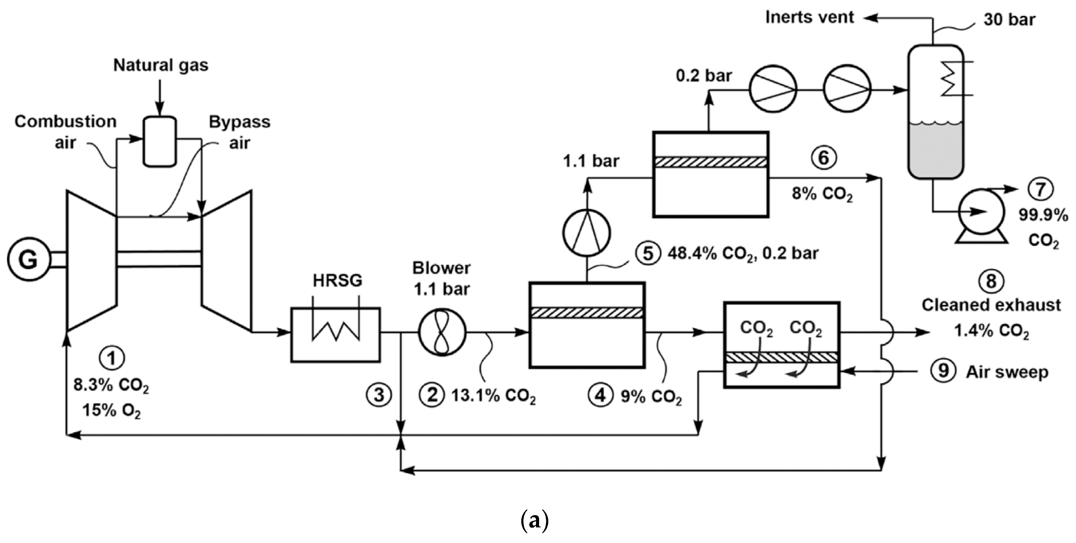
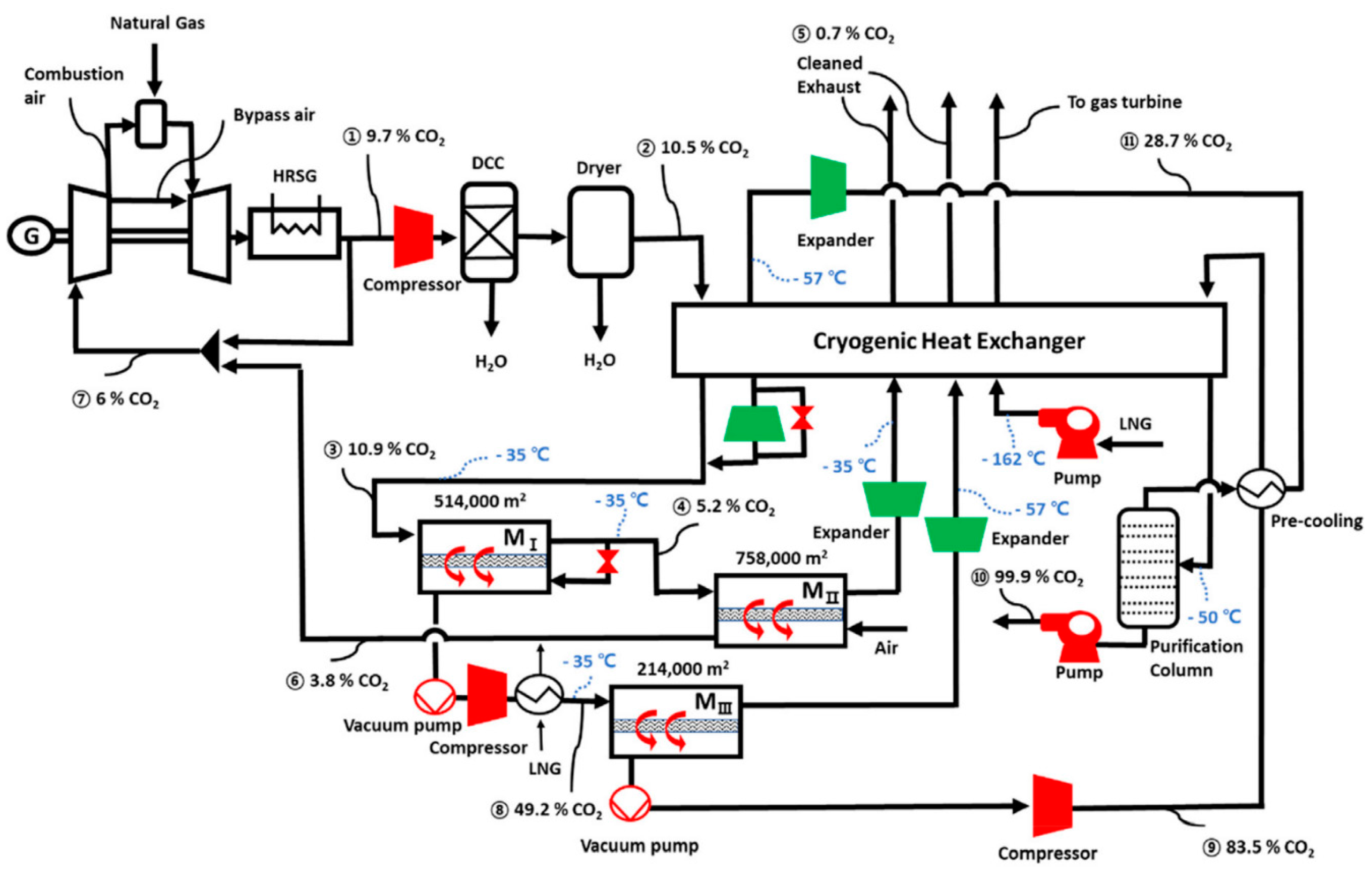
 = compressor;
  = expander;
  = vacuum pump. Stream: warmer color (e.g., red) = higher CO2 concentration; colder color (e.g., blue) = lower CO2 concentration.
= compressor; = expander; = vacuum pump. Stream: warmer color (e.g., red) = higher CO2 concentration; colder color (e.g., blue) = lower CO2 concentration.
= vacuum pump. Stream: warmer color (e.g., red) = higher CO2 concentration; colder color (e.g., blue) = lower CO2 concentration.
= compressor; = expander; = vacuum pump. Stream: warmer color (e.g., red) = higher CO2 concentration; colder color (e.g., blue) = lower CO2 concentration.


| Company/ Institute | Flue Gas Source | Location | Membrane * & Module † Types | Size | Duration | Purity | Recovery |
|---|---|---|---|---|---|---|---|
| SINTEF [56] | Coal | Portugal | FTM; PF | 1.5 m2 | 6.5 months | 75% | N/A |
| HZG [57] | Coal | Germany | PolyActive™; PF | 12.5 m2 | 740 h | 68.2% | 42.7% |
| HYU [60] | N/A | Korea | MMM; PF | 5.67 m2 | N/A | 74% | 22% |
| NTNU [52] | Propane | Norway | FTM; HF | 4.2 m2 | N/A | 60% | N/A |
| NTNU [53] | Cement | Norway | FTM; HF | 18 m2 | 24 days | 65% | N/A |
| NTNU [54] | Cement | Italy | FTM; HF | 200 cm2 | 1 week | 50% | N/A |
| NTNU [55] | Cement | Italy | FTM; HF | 200 cm2 | 2 weeks | 50–55% | N/A |
| KRICT [59] | LNG | Korea | PES; HF | N/A | N/A | 99.2% | 91.5% |
| UM [58] | Coal | Australia | PSf; HF | 5 m2 | 24 h | N/A | N/A |
| UM [58] | Coal | Australia | Polyamide; SW | 7.5 m2 | 98 h | N/A | N/A |
| MTR [35] | Coal | USA | Polaris™; SW | 1 TPD ‡ | 1800 h | N/A | N/A |
| MTR [61] | Coal | USA | Polaris™; SW&PF | 20 TPD | 1000 h | N/A | N/A |
| OSU [38] | Coal | USA | FTM; SW | 1.4 m2 | 500 h | 94.50% | 44% |
Publisher’s Note: MDPI stays neutral with regard to jurisdictional claims in published maps and institutional affiliations. |
© 2020 by the authors. Licensee MDPI, Basel, Switzerland. This article is an open access article distributed under the terms and conditions of the Creative Commons Attribution (CC BY) license (http://creativecommons.org/licenses/by/4.0/).
Share and Cite
Han, Y.; Yang, Y.; Ho, W.S.W. Recent Progress in the Engineering of Polymeric Membranes for CO2 Capture from Flue Gas. Membranes 2020, 10, 365. https://doi.org/10.3390/membranes10110365
Han Y, Yang Y, Ho WSW. Recent Progress in the Engineering of Polymeric Membranes for CO2 Capture from Flue Gas. Membranes. 2020; 10(11):365. https://doi.org/10.3390/membranes10110365
Chicago/Turabian StyleHan, Yang, Yutong Yang, and W. S. Winston Ho. 2020. "Recent Progress in the Engineering of Polymeric Membranes for CO2 Capture from Flue Gas" Membranes 10, no. 11: 365. https://doi.org/10.3390/membranes10110365
APA StyleHan, Y., Yang, Y., & Ho, W. S. W. (2020). Recent Progress in the Engineering of Polymeric Membranes for CO2 Capture from Flue Gas. Membranes, 10(11), 365. https://doi.org/10.3390/membranes10110365