Article

Mechanism of Combustion Noise Influenced by Pilot Injection in PPCI Diesel Engines

College of Power and Energy Engineering, Harbin Engineering University, Harbin 150001, China
*
Author to whom correspondence should be addressed.
Appl. Sci. 2019, 9(9), 1875; https://doi.org/10.3390/app9091875
Submission received: 14 April 2019 / Revised: 30 April 2019 / Accepted: 2 May 2019 / Published: 7 May 2019
(This article belongs to the Special Issue Progress in Combustion Diagnostics, Science and Technology)

Abstract

:
Pilot injection combined with exhaust gas recirculation (EGR) is usually utilized to realize the partially premixed compression ignition (PPCI) mode in diesel engines, which enables the simultaneous decrease of nitrogen oxide and soot emissions to satisfy emission regulations. Moreover, the ignition delay of main injection combustion can also be shortened by pilot injection, and then combustion noise is reduced. Nevertheless, the mechanisms of pilot injection impacts on combustion noise are not completely understood. As such, it is hard to optimize pilot injection parameters to minimize combustion noise. Therefore, experiments were conducted on a four-stroke single-cylinder diesel engine with different pilot injection strategies and 20% EGR as part of an investigation into this relationship. Firstly, the combustion noise was analyzed by cylinder pressure levels (CPLs). Then, the stationary wavelet transforms (SWTs) and stationary wavelet packet transform (SWPT) were employed to decompose in-cylinder pressures at different scales, and thus the combustion noise generated by pilot and main combustion was investigated in both the time and frequency domain. The results show that pilot injection is dominant in the high frequency segment of combustion noise, and main injection has a major impact on combustion noise in the low and mid frequency segment. Finally, the effects of various pilot injection parameters on suppressing combustion noise were analyzed in detail.

1. Introduction

Recently, the requirement of continuous mitigation of particulate matter (PM) and nitrogen oxide (NOx) emissions has become a significant challenge regarding the improvement of combustion in diesel engines. Advanced combustion concepts, such as low-temperature combustion (LTC) and premixed charge compression ignition (PCCI) [1,2,3], have arisen as a solution for the reduction of emissions, but some limitations must still be faced. That is, these advanced combustion concepts cannot be applied for high load operating cases because the fast fuel-burning and heat release of premixed combustion will deteriorate combustion noise. However, the application of the pilot-main injection strategy to the PCCI combustion mode can reduce combustion noise by shortening the ignition delay (ID) of main injection, which is introduced as partially premixed compression ignition (PPCI) [4,5]. In this way, the reduction of combustion noise by pilot injection has the potential to extend the PPCI mode to the full operating condition. Additionally, higher combustion efficiency, and lower CO2 and NOx emissions can be obtained using pilot injection in the PPC mode compared with conventional diesel combustion [6,7,8].
Moreover, the advantages of pilot injection have gained increasing attention, particularly of researchers, regarding the detailed exploration of the effects of pilot injection on combustion noise. It has already been shown that increasing the fuel quantity of the pilot injection or advancing pilot injection timing will result in a progressive decrease of combustion noise [9,10]. However, as reported by Wang Ping et al. [11], the combustion noise can be minimized in the conditions of the moderate pilot injection quantity and dwell. In addition, Alok Warey et al. [12] determined that the minimum combustion noise can be obtained when the energizing dwell between the main and pilot injections decreases below 200 μs. Therefore, throughout these previous combustion noise investigations, it is observed that the conclusions drawn with respect to the pilot injection parameters required to suppress combustion noise are inconsistent. This is probably due to differences of the experimental conditions, but what is foremost is that the influences of pilot injection on combustion noise cannot be interpreted clearly. Meanwhile, the evaluation of combustion noise for situations of varying pilot injection strategies is particularly challenging.
In order to determine the detailed relationship between pilot injection and combustion noise, a robust method is required. Over the last 20 years, numerous methods have been investigated for combustion noise evaluation and analysis. Among these methods, the maximum of the in-cylinder pressure rise rate (MPRR) has been the most intuitive tool for combustion noise assessment [13,14,15,16,17]. In addition, researchers have also demonstrated the existence of an overall relationship between the combustion noise and peak of heat release rate (HRR) [18,19,20]. It is worth noting that pressure spectrum analysis was of utmost importance in combustion noise assessment. Payri et al. proposed a novel combustion noise assessment method on the basis of in-cylinder pressure spectrum decomposition [14,21,22]. Besides, cylinder pressure levels (CPLs) have been widely used in combustion noise analysis [13,19,23,24], and in our previous work, CPLs was synthesized in several frequency segments to investigate the effects of pilot injection on combustion noise [25]. Unfortunately, the CPLs or synthesized CPLs can reveal the overall noise level only in the frequency domain, and the lack of time-domain information limits combustion noise analysis. However, with the application of signal processing techniques to in-cylinder pressure signals, wavelet transforms (WT) and time-frequency analysis have been proposed to further study the relationship between combustion noise and in-cylinder pressure [23,26,27,28]. Considering the limitation of CPLs, WT-based methods are regarded as a powerful tool for decomposition of the in-cylinder pressure signal in both the frequency and time domain, which is suitable for use to determine the combustion noise generated by pilot and main combustion in this study. As a classical method in WT, DWT (discrete wavelet transforms) has several drawbacks essentially [29,30]. SWT (stationary wavelet transforms) is proposed to overcome the disadvantages of DWT [31], which could ascertain the signal information in the frequency domain with high precision. Additionally, for the sake of refining the signal information in the high-frequency segment, SWPTs (stationary wavelet packet transforms) are also used as for subtler multiresolution analysis. Therefore, the two robust signal processing methods, namely SWT and SWPT, are utilized to decompose the in-cylinder pressure signal in this work. Besides, the sub-signals of SWT and SWPT are divided into two phases, namely the pilot and main so that the influences of the main and pilot combustion on combustion noise are analyzed individually in different frequency ranges.
Therefore, in this paper, the mechanisms of pilot injection impacts on combustion noise were analyzed on the basis of the experimental data from a single-cylinder direct injection diesel engine operated in high load. The experimental data was measured under a range of pilot injection parameters with an engine speed of 1500 rpm, injection pressure of 125 MPa, indicated mean effective pressure of 1.01 MPa, and exhaust gas recirculation ratio of 20%. At first, the combustion noise was analyzed by CPL. Then, in order to analyze the combustion noise more separately, SWT and SWPT were employed to decompose the in-cylinder pressure in different scales, and the sub-signals were divided into two phases: pilot and main.

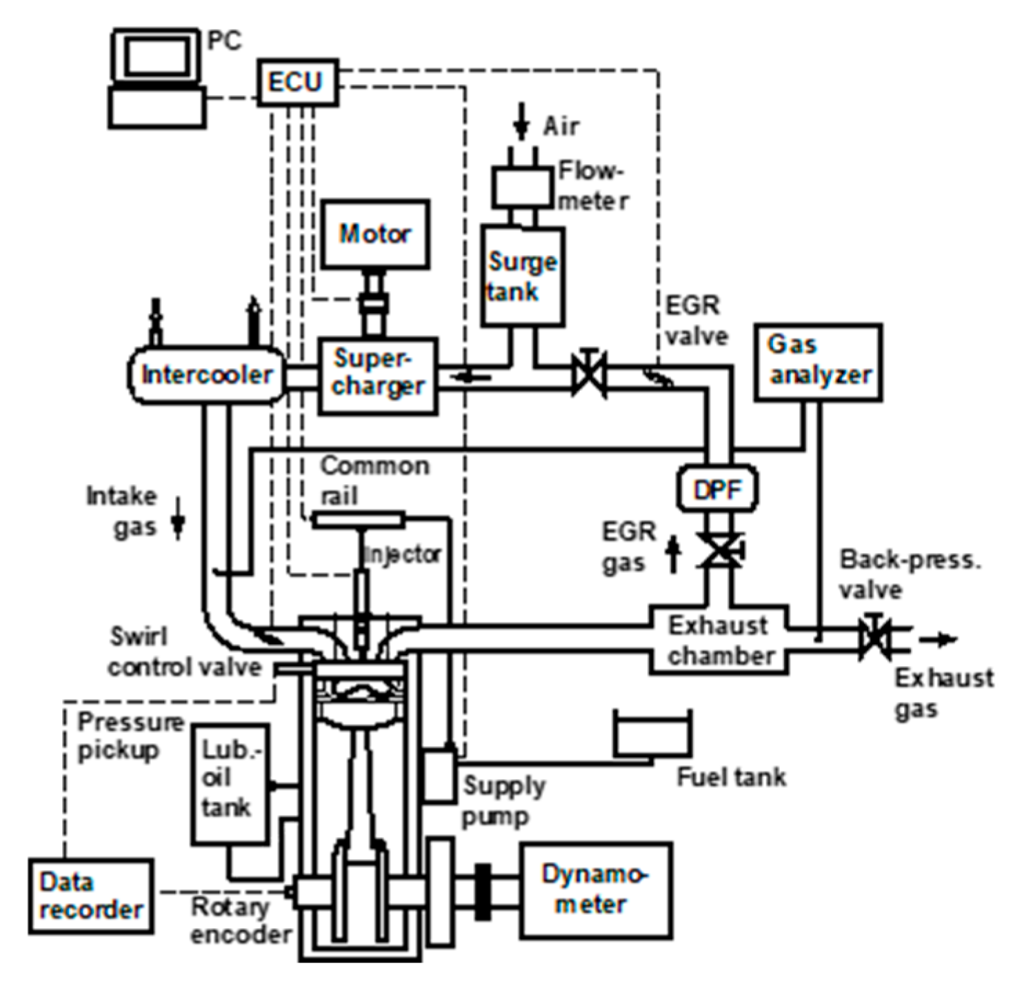
2. Experimental Setup

Figure 1 reveals the outline of the experimental system. The engine was a four-stroke diesel engine with water cooling with a common-rail electronic injection system. Table 1 illustrates the fundamental specifications of the engine, and the experimental conditions are listed in Table 2. The experiments were conducted at a fixed speed of 1500 rpm and the indicated mean effective pressure (IMEP) was kept at 1.01 MPa, which is high-load operation conditions for the test engine. The intake pressure and intake temperature were 1.68 bar and 30 °C, respectively. Furthermore, in these experiments, the injection pressure was set at 125 MPa. The swirl ratio and main spray injection timing were fixed at 2.0 and 1° ATDC, respectively. A piezoelectric pressure transducer (Kistler 6052A, Winterthur, Switzerland) was used for the in-cylinder pressure measurement. Fifty cycles of the averaged pressure were utilized of to calculate the HRR.

3. Results and Discussion

As discussed in the following paragraphs, the in-cylinder pressures of the PPCI diesel engine were processed by several methods. Additionally, parametric investigation of the pilot injection quantity and the start of pilot injection were assessed for combustion noise analysis.

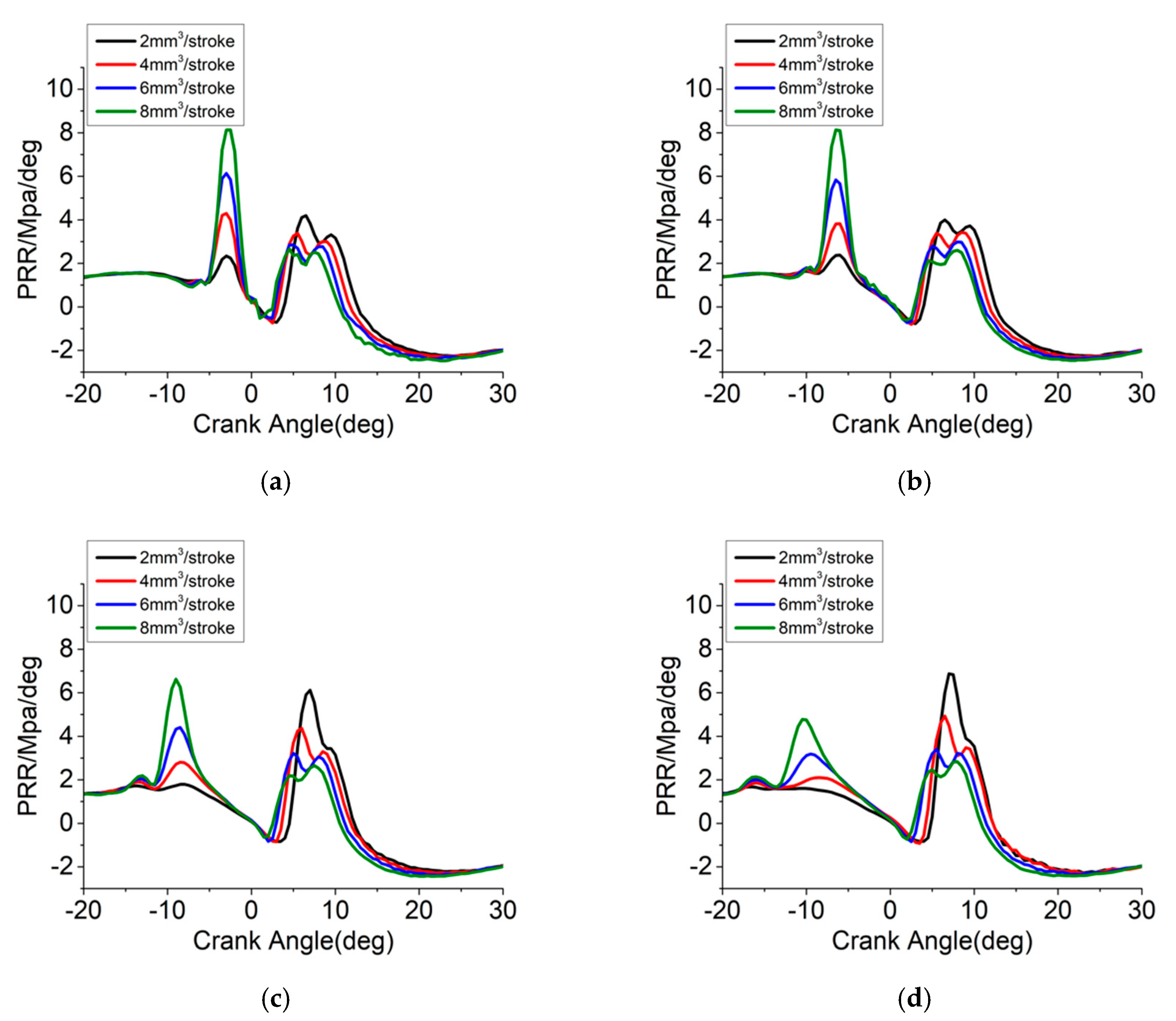
3.1. Analysis of In-Cylinder Pressure and Heat Release Rate

The in-cylinder pressures and HRR for the pilot mass of 2, 4, 6, and 8 mm3 with the pilot injection timing varied from −9 to −24° ATDC in steps of 5 degree (deg) are indicated in Figure 2a–d. It is obvious that as the pilot injection mass becomes larger, the in-cylinder pressure becomes higher, as well as the HRR peaking during pilot injection combustion. This leads to higher in-cylinder temperature before the main spray, and the heat release of premixed combustion during the main spray becomes gentler. Therefore, the first HRR peak during main injection combustion drops as the pilot injection quantity increases. Meanwhile, as the pilot injection mass is increasing and the total quantity of injection fuel is fixed, the decrease of the main injection mass causes a lower HRR peak of the diffusion combustion during main spray combustion (second HRR peak for main combustion). Moreover, with the crank angle of the pilot injection advanced, the HRR of the pilot injection combustion decreases, yet the main spray combustion achieves a high value of HRR.
According to the characteristics of HRR, the variations of the in-cylinder pressure rise rate (PRR) are shown in Figure 3a–d. A larger pilot mass results in a higher maxima pressure rise rate (MPRR) during pilot spray combustion and a lower MPRR for main injection combustion. A smaller MPRR for pilot combustion and a larger MPRR for main combustion is observed with earlier pilot injection timing. Particularly, the PRR of main and pilot spray combustion show contrary variations as the amount of pilot injection fuel is changed, so that it is hard to evaluate the combustion noise.

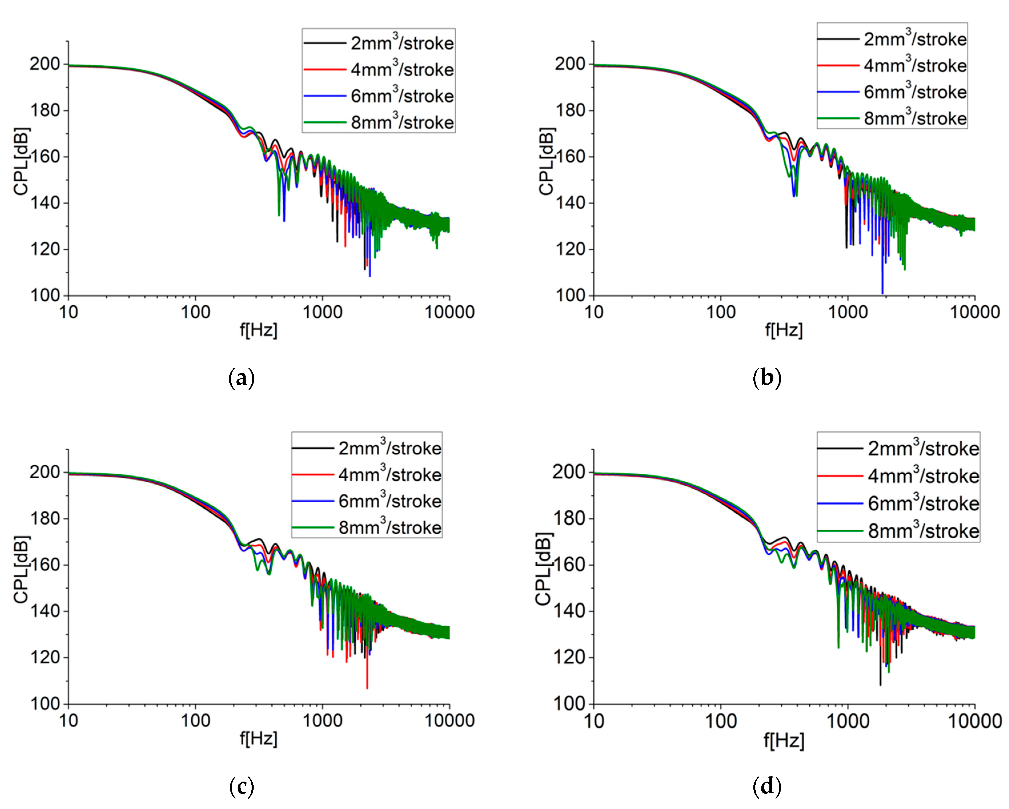
3.2. Combustion Noise Analysis by Cylinder Pressure Levels

As known, frequency domain information is suitable for the assessment of combustion noise. In this section, fast Fourier transforms (FFT) was applied on measured in-cylinder pressure, so that the in-cylinder pressure data could be transformed to the frequency domain. Then, the sound pressure levels (SPLs) were expressed as cylinder pressure levels (CPLs), which was formulated as follows:
CPL = 20 log ( P / P 0 ) ,
where P0 and P are the reference sound pressure and in-cylinder pressure, respectively. P0 was set as 20 μPa in this paper.
The results of CPLs in the situations of pilot injection timing varied from −9 to −24° ATDC and are shown in Figure 4a–d. For the case that the pilot injection timing is −24° ATDC, it is indicated that the increase of pilot injection mass generally results in a drop of the CPL amplitudes. Therefore, in this situation, the evaluation of the combustion noise level lies on the main injection combustion. Nevertheless, when the pilot injection timing comes to −9° ATDC, the variation of the CPLs is relatively complex. That is, in the medium frequency range of 200 to 1000 Hz, a larger amount of pilot injection causes lower CPLs with intense amplitude fluctuations. However, on the contrary, the tendency in the high-frequency segment (higher than 1000 Hz) is that a larger pilot quantity results in higher amplitudes of CPLs. Actually, the combustion excitation imposed on the piston increases the in-cylinder pressure and power output, and is primarily responsible for the CPLs in the mid-frequency segment (200–1000 Hz). Hence, it can be inferred that the CPLs in the mid frequency segment are mainly influenced by main spray combustion. Besides, as illustrated in Figure 3a, the MPRR of pilot injection occurs in approximately −2° ATDC when the pilot injection timing is −9° ATDC. So, the most violent combustion is induced near the top death center (TDC), causing remarkably high frequency pressure oscillations and radiated noise emission. Accordingly, in the high frequency segment (higher than 1000 Hz), the pilot injection combustion may principally influence the CPLs.

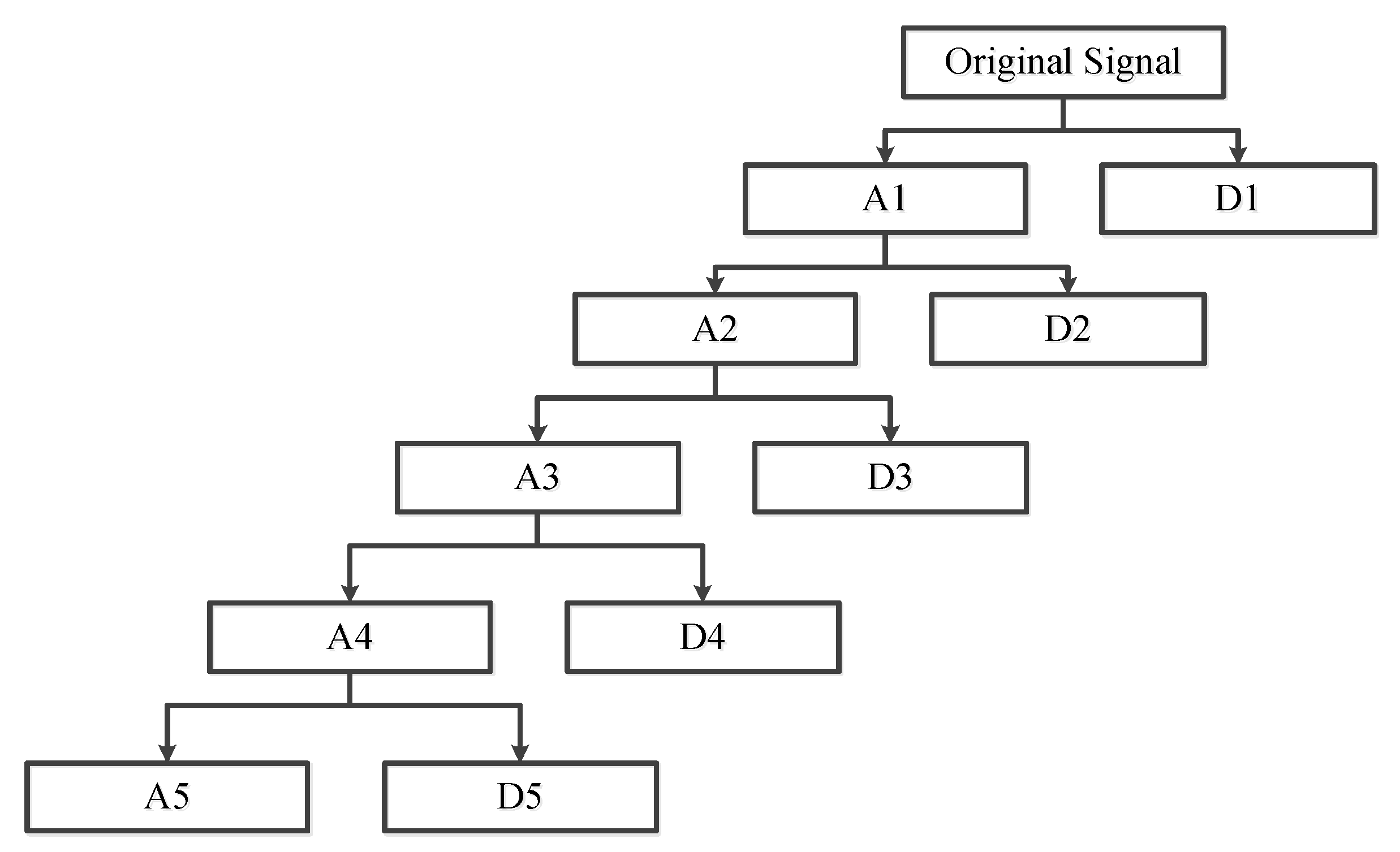
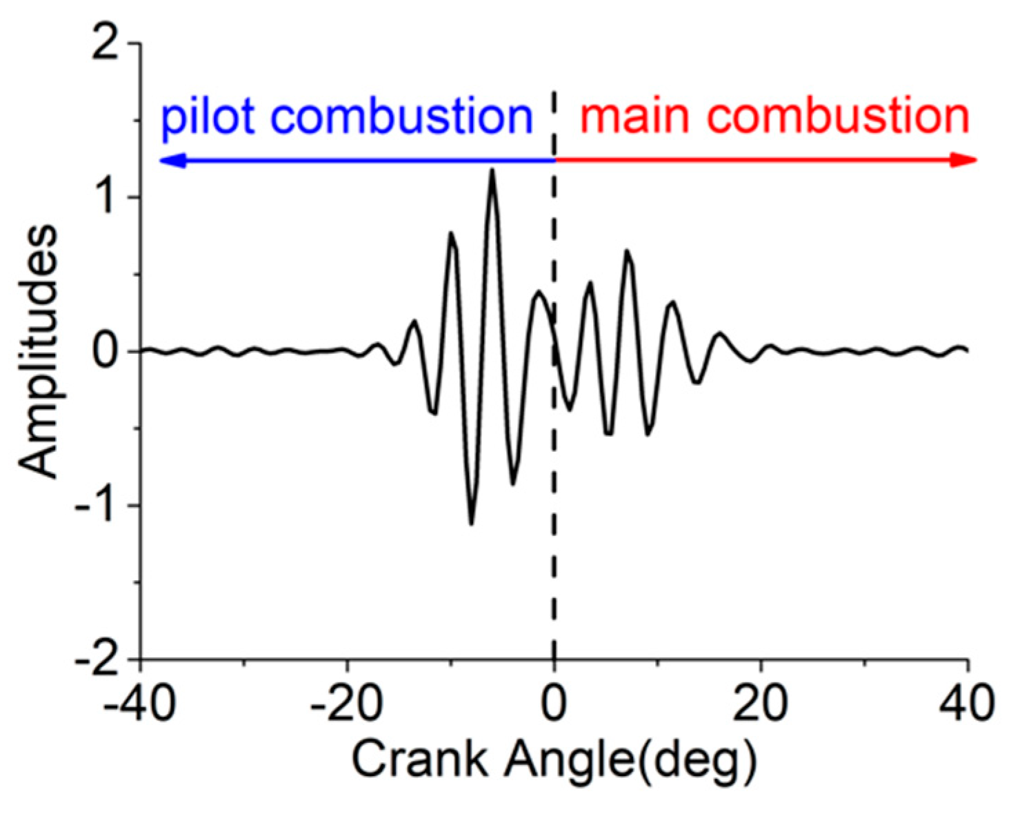
3.3. SWT of In-Cylinder Pressure Signals

Although CPLs can illustrate the impacts of the pilot and main injection on combustion noise, the analysis proceeds only based on the overall combustion noise level and the effects of the pilot and main injection on combustion noise have not been extracted separately. Therefore, a signal decomposition technique is required in this section. DWT has been proven to be an effective tool for decomposing signals. An approximation and a detailed sub-signal are obtained by the decomposition of a single step DWT, which contains the low and high-frequency components of the original signal. However, the procedures of up and down sampling in DWT lead to aliases of the sub-signals [29]. Therefore, the wavelet energy of the sub-signals, which is regarded as an important quantifier for signal intensity [28], cannot be compared precisely. However, in order to address the issues of DWT, a powerful wavelet transform algorithm called SWT is carried out. Instead of the upsampling and downsampling of the signal in DWT, upsampling of the filter coefficients is employed in SWT, and consequently the translation-invariance is accomplished. Thus, each level of SWT contains the same number of samples as the input. Figure 5 shows the tree structures of five-layer SWT. However, SWT can only decompose approximations, namely low and mid-frequency segments. Therefore, SWT is only suitable for the analysis of combustion noise in low and mid frequency ranges.
In this research, using Daubechies 10 as the wavelet, in-cylinder pressure was decomposed into five layers by SWT, including an approximation (A5) and five details (D1, D2, D3, D4, D5). Table 3 shows the frequency band of each sub-signal. The sub-signals, D5 and D4, were selected to investigate the combustion noise in the low and mid frequency segments. Nevertheless, the influences of the pilot and main combustion had to be separated. Thus, the sub-signals were divided into two phases: Pilot and main, as presented in Figure 6. The quantifier of combustion noise intensity was the wavelet signal energy, which is defined as:
E i , n = k = 1 j | x n , k | 2 ,
where integer n represents a sub-signal serial number, x n , k is the SWT coefficient, integer j is the coefficients number, integer k is the index of coefficients, and integer i is the layer number. Hence, the combustion noise of the pilot and main combustion could be evaluated in the low and mid frequency segments.
Figure 7a–d present the combustion noise energy of D4 and D5 during the pilot combustion phase for the condition of various pilot injection timing and pilot injection quantity. As can be seen, the values of combustion noise energy in the low-frequency segment (D5) initially drop, and subsequently rise with the increasing pilot injection quantity. It can be interpreted that a larger amount of pilot injection fuel causes more violent pilot combustion, and partial energy in the low-frequency range may transfer to the high-frequency segment, which will be discussed in the next section. However, when the pilot mass is extremely large (8 mm3), the combustion noise energy level for all the frequency ranges is largely increased. In addition, advancing the pilot injection timing will also enlarge the combustion noise energy generated by pilot combustion in the low-frequency domain. That is because an extension of the heat release duration of pilot combustion will smooth the process of pilot combustion, which mitigates the mid and high frequency combustion noise energy, as revealed by D4 in Figure 7. Hence, the energy of combustion fluctuation is mainly concentrated on the low-frequency segment. Moreover, for the mid-frequency range, a larger pilot quantity results in higher combustion noise energy. That can be explained by the fact that the PRR plays a key role in the mid-frequency combustion noise [22], and PRR rises as the quantity of pilot injection fuel increases (as illustrated in Figure 3), which causes higher mid-frequency combustion noise energy.
The main combustion noise energy of D4 and D5 is also revealed in Figure 8a–d. The comparisons between various pilot injection parameters indicate clearly that a larger pilot injection quantity (lower main injection quantity) causes lower combustion noise energy during main combustion in both the low and mid-frequency domains. Specifically, in the mid-frequency range, with the pilot injection timing advanced, the main combustion noise energy of the small pilot quantity condition (2 and 4 mm3) rises as well, but that changes slightly for the large pilot injection timing condition (6 and 8 mm3). These trends are consistent with the PRR in Figure 3: The PRR during the main combustion phase for the pilot injection quantity of 2 and 4 mm3 rises greatly as the pilot injection timing advances, however, the changes of the PRR for the large pilot injection quantity are not obvious. In addition, from the comparison with Figure 7 and Figure 8, it can be seen that main spray combustion generates more combustion noise energy than pilot injection for all the pilot injection timings in both the low and mid-frequency ranges. Thus, main injection has a dominant impact on low and mid-frequency combustion noise.
The main combustion noise energy of D4 and D5 is also revealed in Figure 8a–d. The comparisons between various pilot injection parameters indicate clearly that a larger pilot injection quantity (lower main injection quantity) causes lower combustion noise energy during main combustion in both the low and mid-frequency domains. Specifically, in the mid-frequency range, with the pilot injection timing advancing, the main combustion noise energy of the small pilot quantity condition (2 and 4 mm3) rises as well, but that changes slightly for the large pilot injection timing condition (6 and 8 mm3). These trends are consistent with the PRR in Figure 3: The PRR during the main combustion phase for the pilot injection quantity of 2 and 4 mm3 rises greatly with the pilot injection timing advancing, however, the changes of the PRR for the large pilot injection quantity are not obvious. In addition, from the comparison with Figure 7 and Figure 8, it can be seen that main spray combustion generates more combustion noise energy than pilot injection for all the pilot injection timings in both the low and mid-frequency ranges. Thus, main injection has a dominant impact on low and mid-frequency combustion noise.

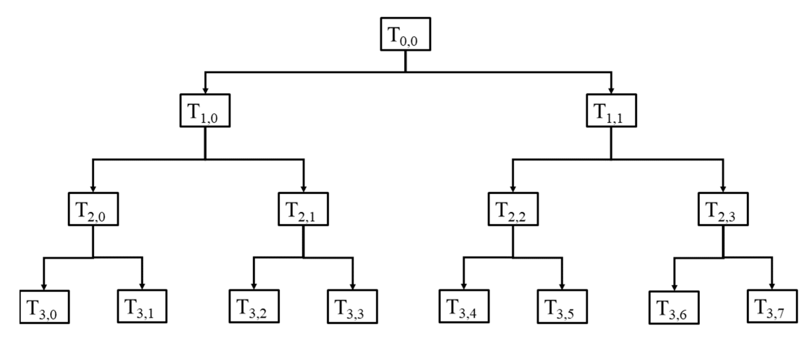
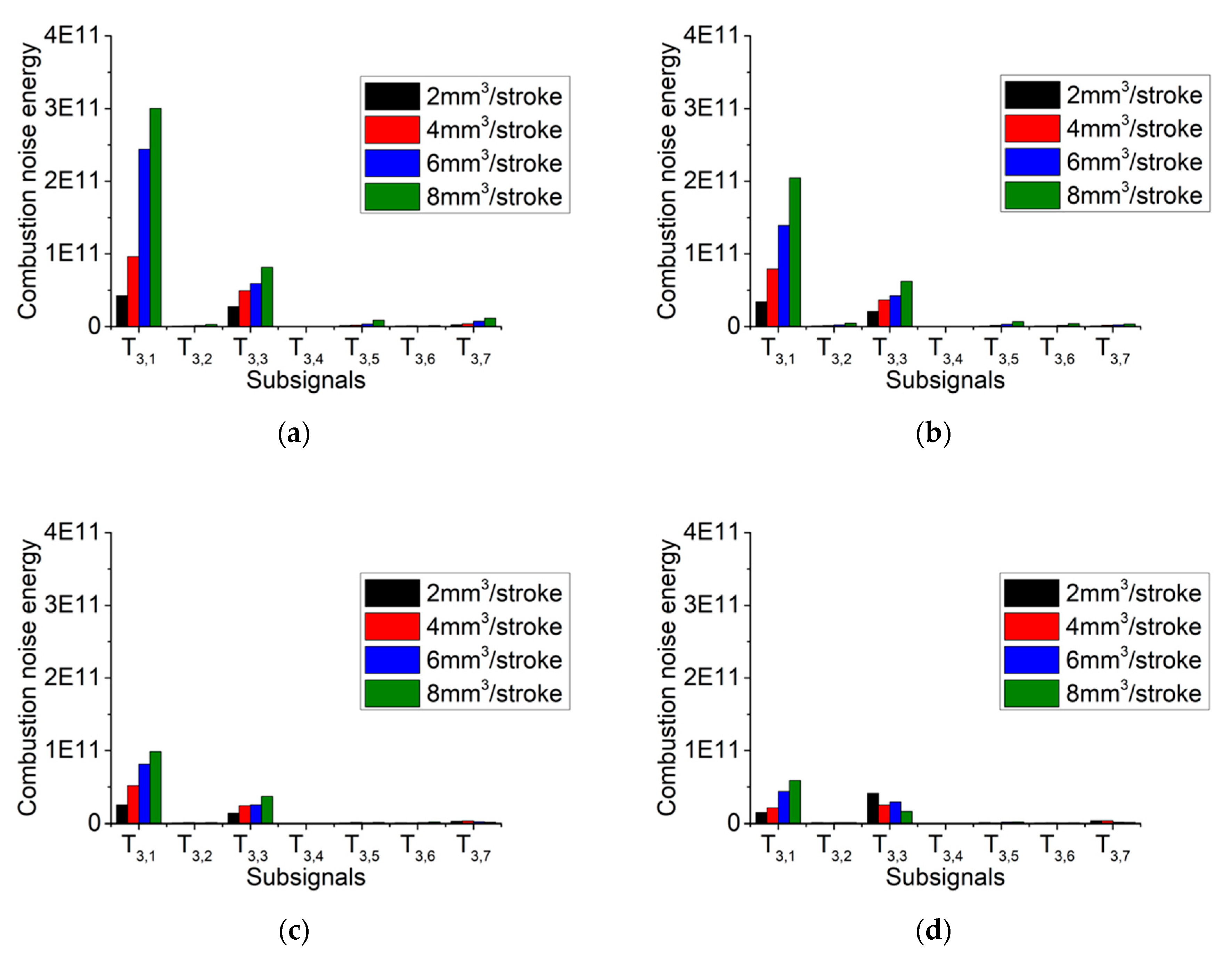
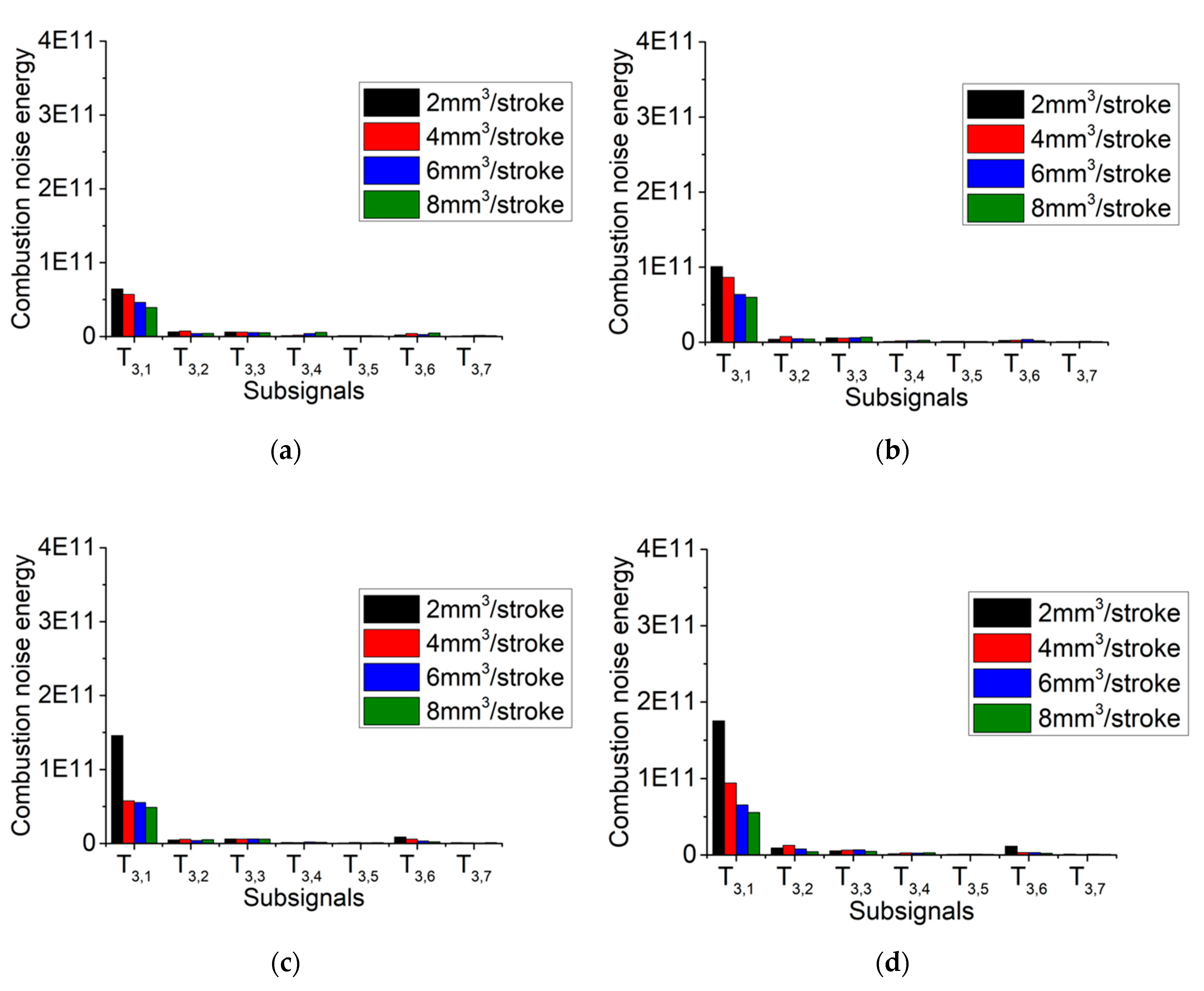
3.4. SWPT of In-Cylinder Pressure Signals

From the previous section, the influences of the pilot and main combustion on low and mid-frequency combustion noise were analyzed separately. However, combustion noise in the high-frequency domain plays a key role in radiated noise as well, which should be investigated in detail. According to Figure 5, SWT could only decompose approximations, from which it is hard to obtain the information for high-frequency components. Nevertheless, SWPT can simultaneously separate the approximations and details of the signal, which would be expected to refine the combustion noise energy in the high-frequency segment. Therefore, with Daubechies 10 as the wavelet, SWPT was performed and the in-cylinder pressure signal was decomposed into three layers. Figure 9 shows the tree structure of the three-layer SWPT. Here, T3,n symbolizes sub-signal n in the third layer. The frequency range of each sub-signal is listed in Table 4. The sub-signal, T3,0, was not used to investigate high-frequency combustion noise, due to the fact that it only contains information about the low and mid frequency segment.
In this section, the sub-signals are also divided into two phases just like the previous section, and the pilot and main combustion noise energy in the high-frequency domain were both calculated using the same computational method (Equation (2)). The results are shown in Figure 10 and Figure 11. Obviously, pilot injection influences the combustion noise energy of the sub-signals, T3,1 and T3,3, whose frequency bands are 1125–2250 Hz and 3375–4500 Hz, respectively. Furthermore, a larger pilot injection quantity results in higher combustion noise energy in general. Additionally, the combustion noise energy level drops with the pilot injection timing advancing, which corresponds to the inference in Section 3.3. Additionally, Figure 11 depicts the main combustion noise energy in the high-frequency domain. It is worthy to note that the main injection only affects the sub-signal, T3,1, corresponding to the frequency segment of 1125–2250 Hz. When the pilot injection mass increases, the combustion noise energy of the main injection is progressively reduced. Besides, earlier pilot injection timing causes a larger main combustion noise energy only in the case with a pilot injection quantity of 2 mm3, and significant changes are not observed for conditions of other pilot masses, which reveals that the influence of the pilot injection timing on combustion noise energy during main combustion is quite small.
Furthermore, for the purpose of determining the significant factor that influences high-frequency combustion noise, comparisons between pilot and main combustion noise energy, namely Figure 10 and Figure 11, were carried out. In the condition of retarded pilot injection timing, just like –9° ATDC, although the pilot mass (2 mm3) is relatively smaller than the amount of main injection fuel (30 mm3), the combustion noise energy of pilot injection is nearly equal to that of main injection. In addition, the pilot combustion noise energy is significantly larger than the main combustion noise energy when the pilot quantity increases over 2 mm3. Considering the results of the comparisons, with the retarded pilot injection timing, the pilot combustion shows remarkable effects on the high-frequency combustion noise. Nevertheless, for the early crank angle of pilot injection, only in the situation of a small pilot mass does the combustion noise energy of main injection dominate. Hence, pilot injection mainly affects the combustion noise in the high-frequency domain.
In addition, the frequency components of the in-cylinder pressure spectrum above 1000 Hz were correlated with the noise radiated [32]. Accordingly, it is feasible to optimize the pilot injection parameters for the mitigation of combustion noise on the basis of the high frequency combustion noise energy analysis. The overall combustion noise energy (pilot and main combustion) of the high frequency segment was calculated, which is shown in Figure 12. It can be seen that a large pilot injection quantity (6, 8 mm3) should not be combined with late pilot injection timing (−9, −14° ATDC), which leads to excessive combustion noise energy during pilot combustion. Similarly, it is also unreasonable to combine the small pilot injection quantity (2 mm3) with early pilot injection timing (−24° ATDC), which enlarges the main combustion noise energy. Instead, aiming at suppressing combustion noise energy, It is suitable to select a large pilot mass (6, 8 mm3) with advanced pilot injection timing (−19, 24° ATDC) and a small pilot quantity (2 mm3) with retarded pilot injection timing (−9, −14° ATDC).

4. Conclusions

In the present study, the influences of pilot injection on combustion noise were analyzed using in-cylinder pressure data measured in a single-cylinder diesel engine. The mechanism of pilot and main injection parameters’ effects on combustion noise was captured by means of CPLs, SWT, and SWPT. By means of the analysis and results provided above, conclusions can be stated as follows:
(1)
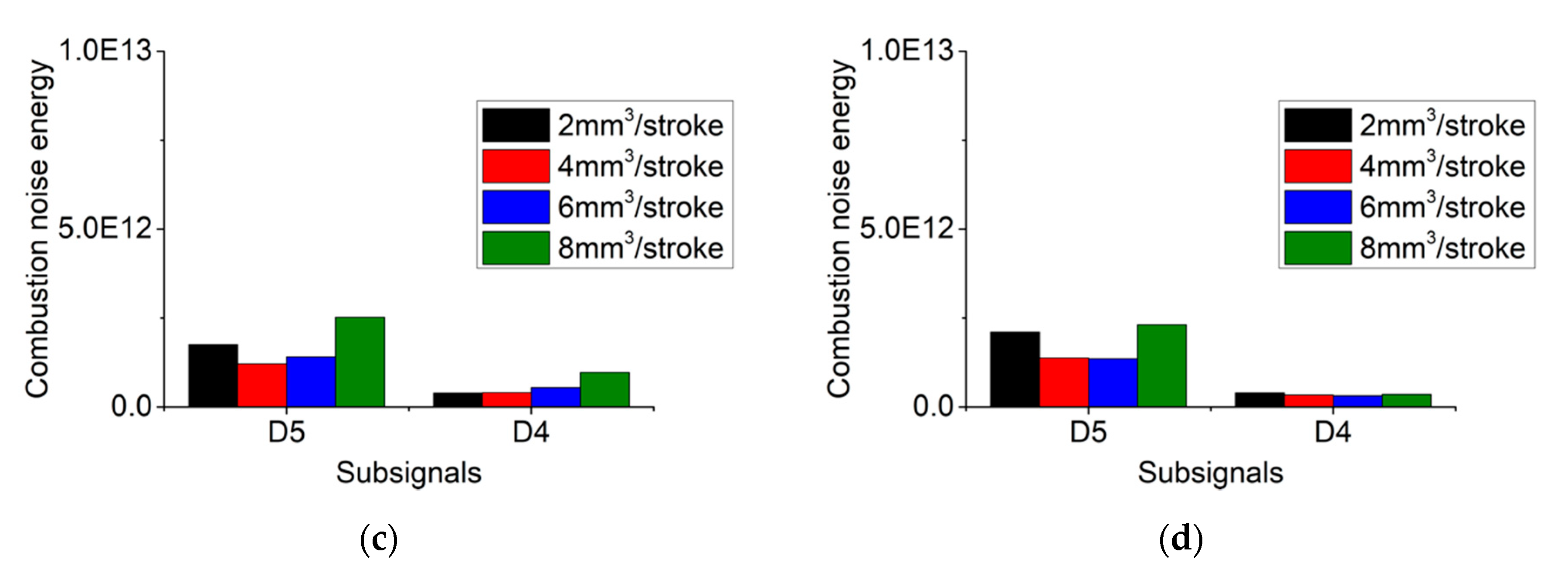
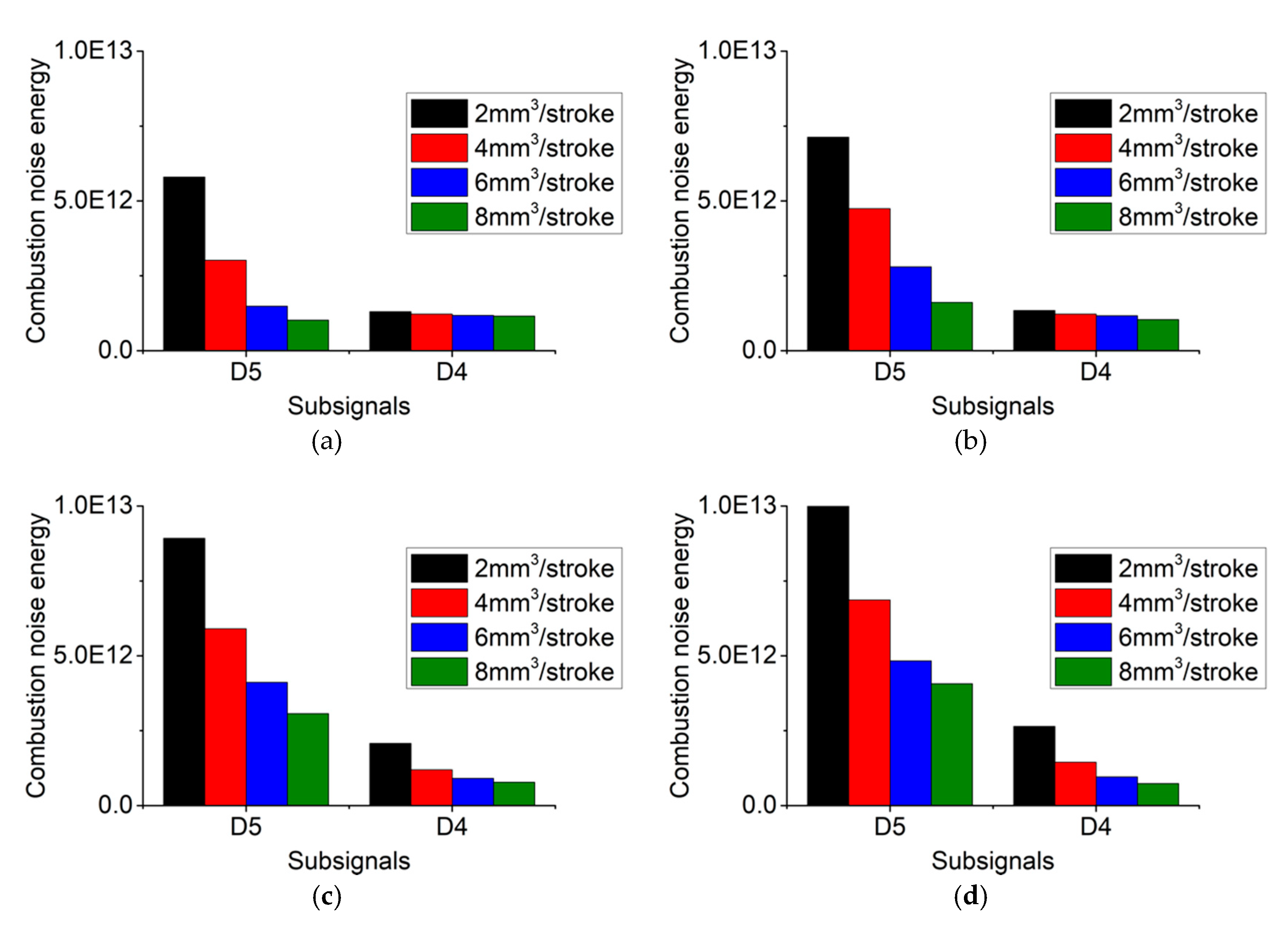
Generally, main injection is the significant factor that affects combustion noise in low and mid frequency segments, and an increase of the pilot mass results in mitigation of combustion noise. Pilot injection plays an essential role in high frequency combustion noise, and larger pilot injection quantities lead to higher combustion noise in the high-frequency domain.
(2)
Advancing pilot injection timing will attenuate pilot combustion noise energy in mid and high frequency domains, but will strengthen that in the low-frequency range. Additionally, an earlier pilot injection timing also leads to higher main combustion noise energy in almost the whole frequency spectrum.
(3)
From the results of SWPT, pilot and main injection combustion impacts on high-frequency combustion noise are concentrated in the frequency band of 1125–2250 Hz and 3375–4500 Hz, and 1125–2250 Hz, respectively.
(4)
According to the view of overall combustion noise energy, a large pilot mass with advanced pilot injection timing and small pilot quantity with retarded pilot injection timing is considered as the optimal pilot injection strategy for the mitigation of combustion noise.

Author Contributions

L.L. proposed the primary research concept. J.D. developed the algorithm and preformed combustion noise analysis. X.C. did the programing work, analyzed the calculated results, and wrote this paper. D.L. performed the experiments and processed the data. X.M. managed the research project.

Funding

This research was funded by the National Natural Science Foundation of China (grant number 51509051), and Marine Power Research and Development Program (grant number DE0302)

Acknowledgments

The experiments presented here had been performed in the Combustion and Power Engineering Laboratory at Kyoto University.

Conflicts of Interest

The author declares no conflict of interest.

References

  1. Seamoon, Y.; Changhee, L. Exhaust Gas Characteristics According to the Injection Conditions in Diesel and DME Engines. Appl. Sci. 2019, 9, 647. [Google Scholar]
  2. Keeler, B.; Shayler, P.J. Constraints on Fuel Injection and EGR Strategies for Diesel PCCI-Type Combustion; SAE Technical Paper; SAE International: Troy, MI, USA, 2008. [Google Scholar]
  3. Kanda, T.; Hakozaki, T.; Uchimoto, T.; Hatano, J.; Kitayama, N.; Sono, H. PCCI Operation with Early Injection of Conventional Diesel Fuel; SAE Technical Paper; SAE International: Troy, MI, USA, 2005; pp. 584–593. [Google Scholar]
  4. Ge, J.C.; Yoon, S.K.; Kim, M.S.; Choi, N.J. Application of Canola Oil Biodiesel/Diesel Blends in a Common Rail Diesel Engine. Appl. Sci. 2017, 7, 34. [Google Scholar] [CrossRef]
  5. Ojeda, W.; Zoldak, P.; Espinosa, R.; Kumar, R. Development of a Fuel Injection Strategy for Diesel LTC; SAE Technical Paper; SAE International: Troy, MI, USA, 2008. [Google Scholar]
  6. Belgiorno, G.; Dimitrakopoulos, N.; Di Blasio, G.; Beatrice, C.; Tunestål, P.; Tunér, M. Effect of the engine calibration parameters on gasoline partially premixed combustion performance and emissions compared to conventional diesel combustion in a light-duty Euro 6 engine. Appl. Energy 2018, 228, 2221–2234. [Google Scholar] [CrossRef]
  7. Belgiorno, G.; Dimitrakopoulos, N.; Di Blasio, G.; Beatrice, C.; Tuner, M.; Tunestal, P. Parametric Analysis of the Effect of Pilot Quantity, Combustion Phasing and EGR on Efficiencies of a Gasoline PPC Light-Duty Engine; SAE Technical Paper; SAE International: Troy, MI, USA, 2017. [Google Scholar]
  8. D’Ambrosio, S.; Gaia, F.; Iemmolo, D.; Mancarella, A.; Salamone, N.; Vitolo, R.; Hardy, G. Performance and Emission Comparison between a Conventional Euro VI Diesel Engine and an Optimized PCCI Version and Effect of EGR Cooler Fouling on PCCI Combustion; SAE Technical Paper; SAE International: Troy, MI, USA, 2018. [Google Scholar]
  9. Torregrosa, A.J.; Broatch, A. Sensitivity of combustion noise and NOx and soot emissions to pilot injection in PCCI Diesel engines. Appl. Energy 2013, 104, 149–157. [Google Scholar] [CrossRef] [Green Version]
  10. Bo, Y.; Long, W.; Le, N.; Ke, Z. Effects of pilot injection timing on the combustion noise and particle emissions of a diesel/natural gas dual-fuel engine at low load. Appl. Therm. Energy 2016, 102, 822–828. [Google Scholar]
  11. Wang, P.; Song, X.; Xue, D.; Zhou, H.; Ma, X. Effect of Combustion Process on DI Diesel Engine Combustion Noise; SAE International: Troy, MI, USA, 2007. [Google Scholar]
  12. Alok, W.; Francesco, P.; Richard, P.; Alberto, V.; Stephen, B.; Kan, Z.; Paul, C. Miles. Experimental and Numerical Investigations of Close-Coupled Pilot Injections to Reduce Combustion Noise in a Small-Bore Diesel Engine; SAE Technical Paper; SAE International: Troy, MI, USA, 2010. [Google Scholar]
  13. Broatch, A.; Margot, X.; Novella, R.; Gomez-Soriano, J. Combustion noise analysis of partially premixed combustion concept using gasoline fuel in a 2-stroke engine. Energy 2016, 107, 612–624. [Google Scholar] [CrossRef]
  14. Payri, F.; Broatch, A.; Margot, X.; Monelletta, L. Sound quality assessment of diesel combustion noise using in-cylinder pressure components. Meas. Sci. Technol. 2009, 20, 1–12. [Google Scholar] [CrossRef]
  15. Broatch, A.; Margot, X.; Novella, R.; Gomez-Soriano, J. Impact of the injector design on the combustion noise of gasoline partially premixed combustion in a 2-stroke engine. Appl. Therm. Eng. 2017, 119, 530–540. [Google Scholar] [CrossRef]
  16. Torregrosa, A.J.; Broatch, A.; Novella, R.; Mónico, L.F. Suitability analysis of advanced diesel combustion concepts for emissions and noise control. Energy 2011, 36, 825–838. [Google Scholar] [CrossRef] [Green Version]
  17. Giakoumis, E.G.; Rakopoulos, D.C.; Rakopoulos, C.D. Combustion noise radiation during dynamic diesel engine operation including effects of various biofuel blends: A review. Renew. Sustain. Energy Rev. 2016, 54, 1099–1113. [Google Scholar] [CrossRef]
  18. Russell, M.F.; Haworth, R. Combustion Noise from High Speed Direct Injection Diesel Engines; SAE Technical Paper; SAE International: Troy, MI, USA, 1985. [Google Scholar]
  19. Zhang, Q.; Hao, Z.; Zheng, X.; Yang, W. Characteristics and effect factors of pressure oscillation in multi-injection DI diesel engine at high-load conditions. Appl. Energy 2017, 195, 52–66. [Google Scholar] [CrossRef]
  20. Russell, M.F.; Cavanagh, E.J. Establishing a Target for Control of Diesel Combustion Noise; SAE Technical Paper; SAE International: Troy, MI, USA, 1979. [Google Scholar]
  21. Payri, F.; Broatch, A.; Tormos, B.; Marant, V. New methodology for in-cylinder pressure analysis in direct injection diesel engines-application to combustion noise. Meas. Sci. Technol. 2005, 16, 540–547. [Google Scholar] [CrossRef]
  22. Torregrosa, A.J.; Broatch, A.; Martín, J.; Monelletta, L. Combustion noise level assessment in direct injection Diesel engines by means of in-cylinder pressure components. Meas. Sci. Technol. 2007, 18, 2131–2142. [Google Scholar] [CrossRef]
  23. Bhat, C.S.; Meckl, P.H.; Bolton, J.S.; Abraham, J. Influence of fuel injection parameters on combustion-induced noise in a small diesel engine. Int. J. Eng. Res. 2012, 13, 130–146. [Google Scholar] [CrossRef]
  24. Hao, Z.; Zhang, Q.; Zheng, X.; Yang, W. Prediction of the overall noise level of DI diesel engine with calculated in cylinder pressure. Meas. Sci. Eng. 2017, 39, 2421–2432. [Google Scholar] [CrossRef]
  25. Liu, L.; Fei, H.; Du, J. Analysis of pilot injection effects on combustion noise in PPCI diesel engines. In Proceedings of the ASME 2016 Internal Combustion Engine Division Fall Technical Conference, Greenville, SC, USA, 9–12 October 2016. [Google Scholar]
  26. Qiao, X.; Hou, J.; Wang, Z. Knock Investigation of a Direct Injection-Homogeneous Charge Compression Ignition Engine Fueled with Dimethyl Ether and Liquefied Petroleum Gas. Energy Fuels 2009, 23, 2006–2012. [Google Scholar] [CrossRef]
  27. Desantes, J.M.; Torregrosa, A.J.; Broatch, A. Wavelet Transform Applied to Combustion Noise Analysis in High-Speed DI Diesel Engines; SAE Technical Paper; SAE International: Troy, MI, USA, 2001. [Google Scholar]
  28. Hou, J.; Qiao, X.; Wang, Z.; Liu, W.; Huang, Z. Characterization of knocking combustion in HCCI DME engine using wavelet packet transform. Appl. Energy 2010, 87, 1239–1246. [Google Scholar] [CrossRef]
  29. Bao, W.; Zhou, R.; Yang, J.; Yu, D.; Li, N. Anti-aliasing lifting scheme for mechanical vibration fault feature extraction. Mech. Syst. Signal Process. 2009, 23, 1458–1473. [Google Scholar] [CrossRef]
  30. Yang, J.; Park, S.T. An anti-aliasing algorithm for discrete wavelet transform. Mech. Syst. Signal Process. 2003, 17, 945–954. [Google Scholar] [CrossRef]
  31. Christen, U.; Vantine, K.; Chevalier, A.; Moraal, P.; Scholl, D. A wavelet-based combustion noise meter. In Proceedings of the IEEE International Symposium on Intelligent Control, Munich, Germany, 4–6 October 2006; pp. 533–538. [Google Scholar]
  32. Dernotte, J.; Dec, J.; Ji, C. Investigation of the Sources of Combustion Noise in HCCI Engines; SAE Technical Paper; SAE International: Troy, MI, USA, 2014. [Google Scholar]
Figure 1. Experimental setup.
Applsci 09 01875 g001
Figure 2. In-cylinder pressure and heat release rates. (a) Pilot injection timing = −9° ATDC; (b) pilot injection timing = −14° ATDC; (c) pilot injection timing = −19° ATDC; (d) pilot injection timing = −24° ATDC.
Applsci 09 01875 g002
Figure 3. In-cylinder pressure rise rates. (a) Pilot injection timing = −9°ATDC; (b) pilot injection timing = −14° ATDC; (c) pilot injection timing = −19° ATDC; (d) pilot injection timing = −24° ATDC.
Applsci 09 01875 g003
Figure 4. Cylinder pressure levels. (a) Pilot injection timing = −9° ATDC; (b) pilot injection timing = −14° ATDC; (c) pilot injection timing = −19° ATDC; (d) pilot injection timing = −24° ATDC.
Applsci 09 01875 g004
Figure 5. Five-layer SWT.
Applsci 09 01875 g005
Figure 6. Pilot and main phases of an arbitrary sub-signal.
Applsci 09 01875 g006
Figure 7. Pilot combustion noise energy of D4 and D5. (a) Pilot injection timing = −9° ATDC; (b) pilot injection timing = −14° ATDC; (c) pilot injection timing = −19° ATDC; (d) pilot injection timing = −24° ATDC.
Applsci 09 01875 g007aApplsci 09 01875 g007b
Figure 8. Main combustion noise energy of D4 and D5. (a) Pilot injection timing = −9° ATDC; (b) pilot injection timing = −14° ATDC; (c) pilot injection timing = −19° ATDC; (d) pilot injection timing = −24° ATDC.
Applsci 09 01875 g008
Figure 9. Tree structure of the three-layer stationary wavelet packet transforms.
Applsci 09 01875 g009
Figure 10. Pilot combustion noise of seven sub-signals. (a) Pilot injection timing = −9° ATDC; (b) pilot injection timing = −14° ATDC; (c) pilot injection timing = −19° ATDC; (d) pilot injection timing = −24° ATDC.
Applsci 09 01875 g010
Figure 11. Main combustion noise energy of seven sub-signals. (a) Pilot injection timing = −9° ATDC; (b) pilot injection timing = −14° ATDC; (c) pilot injection timing = −19° ATDC; (d) pilot injection timing = −24° ATDC.
Applsci 09 01875 g011
Figure 12. Overall combustion noise energy.
Applsci 09 01875 g012
Table 1. Specifications of the test engine.
TypeSingle-Cylinder, Direct-Injection, Water-Cooled Diesel Engine
Bore × Stroke85 mm × 96.9 mm
Displacement550 cc
Compression ratio16.3
Combustion chamberReentrant type
(Cavity diameter: 51.6 mm)
Injection systemCommon-rail system with a solenoid injector (Max. pressure: 180 MPa) 0.125 mm × 7 hole nozzle (Spray angle: 156°)
SuperchargingExternal supercharging
EGR systemLow-pressure loop EGR
Table 2. Engine operating parameters.
Injection pressure125 MPa
Total injection quantity32 mm3/stroke
Pilot injection quantity (qpilot)2, 4, 6, 8 mm3/stroke
Pilot injection timing (θpilot)−9, −14, −19, −24° ATDC
Main injection timing (θmain)1° ATDC
EGR rate20%
Swirl ratio2.0
Table 3. Frequency band of each sub-signal in stationary wavelet transforms.
Sub-SignalsFrequency Band (Hz)
A50–281.25
D5281.25–562.5
D4562.5–1125
D31125–2250
D22250–4500
D14500–9000
Table 4. Frequency band of each sub-signal in the SWPT.
Sub-SignalsFrequency Band (Hz)
T3,00–1125
T3,11125–2250
T3,22250–3375
T3,33375–4500
T3,44500–5625
T3,55625–6750
T3,66750–7875
T3,77875–9000

