Article

Combination of Robust Algorithm and Head-Tracking for a Feedforward Active Headrest

1
Key Laboratory of Noise and Vibration Research, Institute of Acoustics, Chinese Academy of Sciences, No. 21 North 4th Ring Road, Haidian District, Beijing 100190, China
2
School of Electronic, Electrical and Communication Engineering, University of Chinese Academy of Sciences, No. 19(A) Yuquan Road, Shijingshan District, Beijing 100049, China
3
CRRC TANGSHAN Co., LTD., No. 3 Changqian Road, Fengrun District, Tangshan 063035, China
*
Author to whom correspondence should be addressed.
Appl. Sci. 2019, 9(9), 1760; https://doi.org/10.3390/app9091760
Submission received: 26 March 2019 / Revised: 13 April 2019 / Accepted: 24 April 2019 / Published: 28 April 2019
(This article belongs to the Special Issue Active and Passive Noise Control)

Abstract

:
Active headrest can reduce the low-frequency noise around ears based on the principle of active noise control. This paper presents a combination of robust algorithm and head-tracking for a feedforward active headrest to reduce the broadband noise for a sleeper on a high-speed train. A robust algorithm based on the feedforward active noise control is proposed to improve the noise control performance during head rotations. The head-tracking system with infrared rangefinders tracks the head position based on the Kalman filter to further improve system performance with head movements. Experiments were conducted on a model of a sleeper on a high-speed train. The experimental results show that the proposed active headrest system effectively controls broadband noise with head movements and rotations.

1. Introduction

Active noise control (ANC) systems can effectively suppress noise at low frequencies by generating anti-noise with the same amplitude but opposite phase of the undesired noise. It has been widely used in many applications, such as headsets, trains, and cars [1,2,3,4,5]. However, it is difficult to control noise in large areas due to the complexity of the ANC system. Therefore, local ANC is proposed to control the noise in the proximity of an individual’s ears. Active headrest is a popular application of local ANC and has been studied by many researchers [6,7].
The concept of an active headrest was proposed in 1953 by Olson and May [8]. Then, this method became famous when Rafaely and his group built an active headrest prototype system based on feedback ANC algorithm and H 2 /H feedback ANC algorithm, and analyzed its noise control performance in the 1990s [9,10]. Using this system, the noise was controlled at an individual’s ears, where error microphones were inconveniently positioned. Therefore, several remote microphone techniques (RMTs) [11] and virtual microphone arrangements (VMAs) [12] have been proposed to control the noise at a remote location [13,14]. Diaz et al. applied the VMA algorithm to an active headrest system to control the noise at human ears in a prototype of a sleeping car [4], and achieved 16 dB attenuation for band-limited noise (100–300 Hz). However, the noise control performance of the active headrest system with RMTs or VMAs degrades with head movements and head rotations [13]. To accommodate the condition of the head movement, Lei et al. optimized the secondary path model for active headrest to improve noise control with min-max optimization when controlling the tonal noise [15]. Elliott et al. proposed an active headrest to control low-frequency noise with a head-tracking system in which Microsoft Kinect (Microsoft, Washington, DC, USA), was applied [16,17]. However, user privacy issues need to be considered in practical applications for the public, because a camera on the Microsoft Kinect is always open to track the position of the passengers’ heads. In addition, noise control performance degrades when the head rotates with these techniques. Behera et al. designed a hat mounted with microphones to track the position of the ears and then control the tonal noise, even when the head was rotated [18,19]. However, this system is not practical in some applications because a human cannot always wear a hat implemented with microphones.
All these above-stated studies depend on adaptive filters, and error microphones are needed when controlling the noise. Han proposed a robust active headrest in which the control performance does not degrade with head rotations based on the optimal filter, and error microphones are not needed after the optimal filter is obtained if the frequency character of primary noise does not vary with time [20]. However, the performance degrades when the head moves.
In this paper, to solve the aforementioned problems, a combination of a robust algorithm and head-tracking for a feedforward active headrest applied to a model of a sleeper on a high-speed train is introduced to reduce broadband noise. Control performance degradation issues with head rotations and movements when controlling broadband noise are solved. The remainder of the paper is structured as follows. Section 2 describes the design of the optimal filter coefficients with traditional algorithm of the active headrest. Section 3 presents the proposed combination of robust algorithm and head-tracking for an active headrest. Section 4 presents a series of experiments. Results show that the proposed active headrest system could effectively control broadband noise up to 700 Hz independent of head rotations or movements. Section 5 concludes the paper.

2. Design of the Optimal Filter Coefficients of Active Headrest with Traditional Algorithm

The noise data collected on a high-speed railway indicate that the frequency characteristic of the noise is constant [20,21]. Therefore, the proposed active headrest system shown in Figure 1 adopts a fixed optimal filter rather than an adaptive filter for the active headrest. The system remains stable if feedback from the secondary sources to the reference microphone is not considered. After obtaining the optimal filter of the ANC system, error microphones are not needed.
The implementation of the active headrest based on the feedforward algorithm is shown in Figure 1. The signal x ( n ) is the reference signal and P is the primary path transfer function. The primary noise at the error microphones is d l ( n ) . Suppose that there are four secondary loudspeakers and two error microphones. Error microphones are placed at the individual’s ears to reduce the noise at the ears. g l m is the secondary path transfer function from the mth loudspeaker to the lth error microphone. The output of the controller y m ( n ) is obtained by filtering the reference signal x ( n ) with the filter w m .
In the traditional active headrest system, the human head without rotation is positioned at the center of the headrest. The error microphones are placed at the two ears and the error signals e l ( n ) can be expressed as
e l ( n ) = d l ( n ) + m = 1 4 w m T r l m ( n ) .
The order of the filter w m = w m 0 w m 1 w m 1 w m ( I 1 ) T is I, and r l m ( n ) = r l m ( n ) r l m ( n 1 ) r l m ( n I + 1 ) T is the filtered-x signal vector, where
r l m ( n ) = j = 0 J 1 g l m ( j ) x ( n i ) .
The optimal filter coefficient is designed to minimize the sum of the mean square errors of the residual signals e l ( n ) . The cost function can be stated concisely as:
J ( n ) = E [ e 1 2 ( n ) + e 2 2 ( n ) ] .
where E is the expectation operator. To find the optimal w m that minimizes Equation (3), its derivative is calculated with respect to each w m where the derivative is equal to 0.
J w i = m = 1 4 E r 1 i r 1 m T w m + r 2 i r 2 m T w m .
Set w = [ w 1 T w 2 T w 3 T w 4 T ] T and rearrange Equation (4) by w m . Then, we can place the coefficients of w i into a new autocorrelation matrix R .
R = E r 11 r 11 T + r 21 r 21 T r 11 r 12 T + r 21 r 22 T r 11 r 13 T + r 21 r 23 T r 11 r 14 T + r 21 r 24 T r 12 r 11 T + r 22 r 21 T r 12 r 12 T + r 22 r 22 T r 12 r 13 T + r 22 r 23 T r 12 r 14 T + r 22 r 24 T r 13 r 11 T + r 23 r 21 T r 13 r 12 T + r 23 r 22 T r 13 r 13 T + r 23 r 23 T r 13 r 14 T + r 24 r 24 T r 14 r 11 T + r 24 r 21 T r 14 r 12 T + r 24 r 22 T r 14 r 13 T + r 24 r 23 T r 14 r 14 T + r 24 r 24 T .
In addition, the part in Equation (4) that is independent of w m is sorted into Equation (6) to become the new cross-correlation vector
p = E ( r 11 d 1 + r 21 d 2 ) T ( r 12 d 1 + r 22 d 2 ) T ( r 13 d 1 + r 23 d 2 ) T ( r 14 d 1 + r 24 d 2 ) T T .
Thus, the optimal filter w is derived as
w o p t = R 1 p .

3. Proposed Active Headrest with Robust Algorithm and Head-Tracking

The active headrest with traditional non-adaptive algorithms, derived in Section 2, achieves a noise control effect at the ears with no head movements and rotations. In this section, a robust algorithm is derived to improve the noise control performance with head rotations. Furthermore, a head-tracking system based on a Kalman filter is proposed in Section 3.2. Schematic diagram of the active feedforward headrest integrated with head-tracking is shown in Figure 1. The proposed active headrest retrieves the precalculated filter coefficients using the position of the head obtained by the head-tracking system.

3.1. Robust Algorithm for the Active Headrest

The traditional algorithm derived in Section 2 only achieves the best noise control performance at both ears when the head is at a fixed position and rotation. The secondary path along with the position of ears changes with head rotations. If the optimal filter coefficient is obtained with Section 2, then several early-stage experiments show that the noise control at the left and right ears is severely degraded when the head rotates [20]. When the head rotates 90 toward the right, the secondary path from the loudspeakers to the left ear changes significantly; thus, the noise reduction at the left ear can be 7 dB less than that at the right ear.
To release the degradation of noise control performance when the head rotates, the robust algorithms has been proposed. In the robust algorithm, the residual noises at the ears when the head rotates leftward 60 , rightward 60 and has no rotation, are simultaneously added to the cost function. Thus, the error points are equally spaced to divide the total angular range through which the human head can rotate into six parts. Therefore, the cost function becomes
J r o b u s t = i = 1 3 E e 1 i 2 ( n ) + e 2 i 2 ( n ) .
where e 1 i ( n ) and e 2 i ( n ) are the error signals at the two ears when the head rotates leftward 60 , rightward 60 , and has no rotation, respectively. Primary noise at the ears and the transfer functions of secondary path when the head rotates to different angles are obtained in advance. The optimal filter coefficients in the robust algorithm are derived as
w o p t = i = 1 3 R i 1 i = 1 3 p i ,
where R i and p i are the autocorrelation matrix as Equation (5) and the cross-correlation vector as Equation (6), respectively, when the head rotates to different angles.
More error residual signals need to be controlled using the robust algorithm than the traditional algorithm. The active headrest with the robust algorithm achieves control performance when the head rotates to other angles based on the fact that the ANC achieves certain noise reduction in the surrounding space of the control target [15,22].

3.2. Head-Tracking System

When the head position changes, the secondary path of the active headrest system will also greatly change. Hence, the performance further degrades. To solve this problem, a head-tracking system is designed for a sleeper in a high-speed train, as shown in Figure 2. The head-tracking system consists of nine infrared rangefinders. Five rangefinders are placed on the top of the head, marked as No. 1–No. 5, and four rangefinders are placed on both sides of the head, marked as No. 6–No. 9. The coordinate value of the center of the head is acquired with the head-tracking system.
The shortest distance is measured by rangefinders No. 1–No. 5 and then 100 mm is added as the coordinate value of the y-axis of the head center, where 100 mm is the distance from the top to the center of the head. Then, the coordinate value of the x-axis of the head position is obtained by rangefinders No. 6–No. 9 located on both sides of the head. If the measured coordinate value of the y-axis is less than 200 mm, then rangefinders No. 6 and No. 7 work, otherwise rangefinders No. 8 and No. 9 work. The x-axis coordinate value of the head center is derived from the distance information of the two rangefinders and the total width of the sleeper.
There is measurement error during the acquisition of the coordinates. Therefore, the measured coordinate values M = x , y are then processed by a Kalman filter to decrease the noise in the measurement [23]. The Kalman filter model assumes that the true coordinate value Z ( n ) = x , y T at time n evolves from the coordinate value Z ( n 1 ) according to
Z ( n ) = F Z ( n 1 ) + u ( n ) .
Equation (10) shows how we estimate the true coordinate values at the current time from the coordinate values at the previous time. u ( n ) represents the estimation noise. Suppose the x and y coordinates are independent of each other, thus the state-transition model F is identity matrix. The coordinate values at the current time is obtained by adding noise to the coordinate values at the previous time [24].
The measurement M ( n ) of the true state Z ( n ) at the current time is made according to
M ( n ) = H Z ( n 1 ) + v ( n ) .
Equation (11) presents how we obtain the observed coordinate values from the true coordinate values. v ( n ) represents the observation noise. The observation model H is identity matrix on the assumption that the x and y coordinates are independent of each other. Z ( n ) is estimated from M ( n ) as Equation (12) based on the Kalman filter [25].
Z ^ ( n ) = F Z ^ ( n 1 ) , P ( n ) = F P ( n 1 ) F H + Q , K ( n ) = P ( n ) H H ( H P ( n ) H H + R ) 1 , Z ^ ( n ) = Z ^ ( n ) + K ( n ) ( M ( n ) H Z ^ ( n ) ) , P ( n ) = P ( n ) K ( n ) H P ( n ) .
Q and R are covariance matrices of noise in estimation u ( n ) and observation processes v ( n ) , respectively. Their values depend on the degree of trust in the estimation and observation processes. Validation experiments were conducted to verify the accuracy of the tracking system. The results show that the difference between the x-axis and y-axis coordinates of the true position of the head’s center and the output of the tracking system was less than 1 cm. When the coordinate value of the head changed, the delay of the head-tracking system was less than 1 s.
The human head can be moved to any position. Considering that ANC has a certain noise reduction effect at the error microphones when the secondary paths change little, we divide the area where the human head may move into 25 regions, marked as No. 1–No. 25, as shown in Figure 2. The size of each region is 8 cm × 5 cm. When the center of the head is located in one of the divided regions, the optimal filter coefficient that is precalculated when the head is at the center of the current region is retrieved.

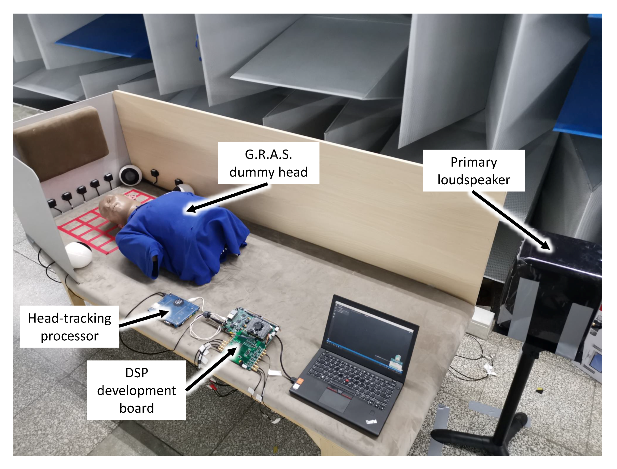
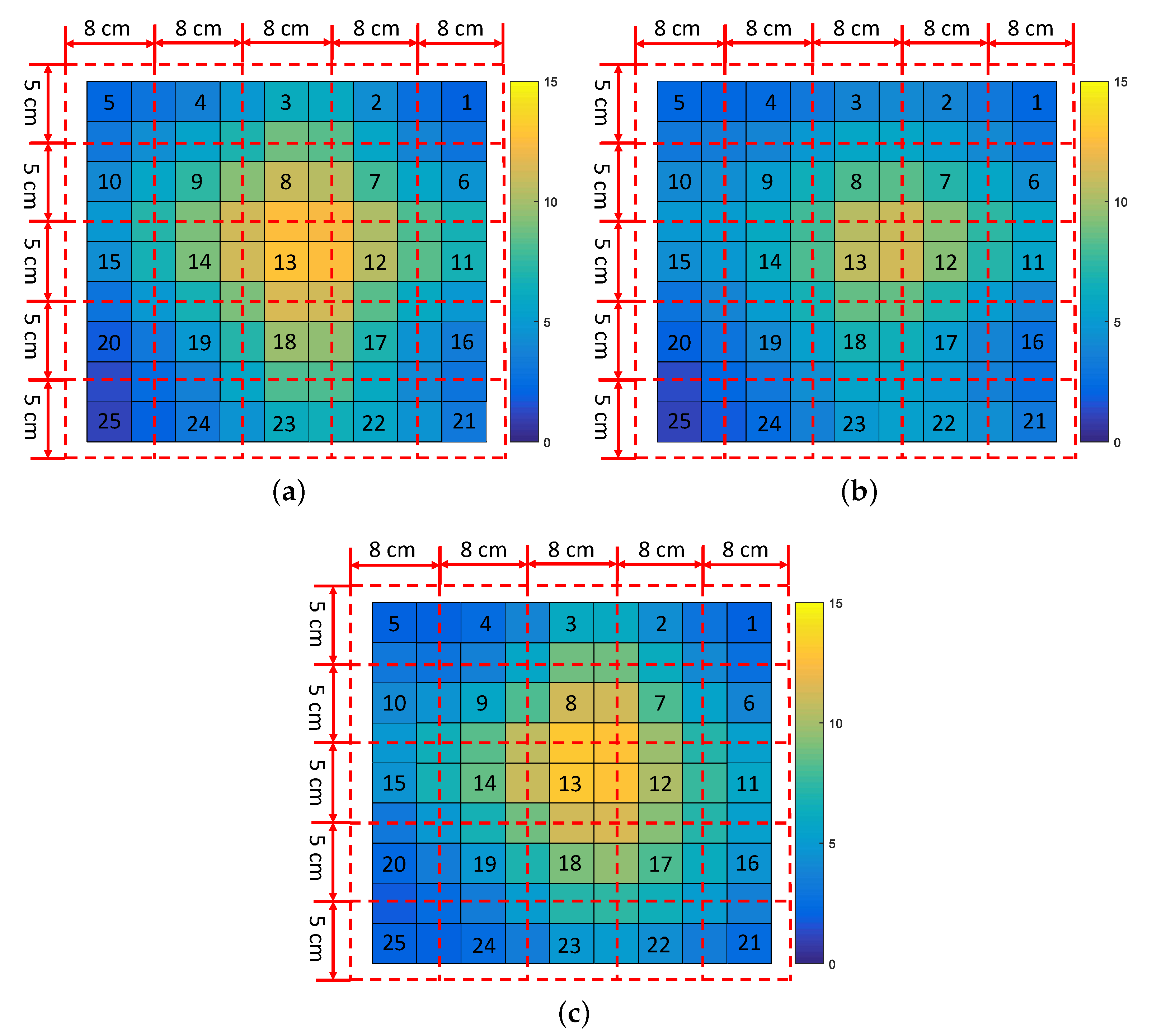
4. Experiments and Noise Control Performance

Experiments were conducted in a semi-anechoic room. As shown in Figure 3, a dummy head with torso was placed on the model of a sleeper on a high-speed railway. The sampling frequency of the noise control system was 16 kHz. The primary sound source was placed approximately 2 m from the ears of the dummy head. Measured noise on the high-speed railway denoted that the main frequency component of the broadband noise in the cabin was below 700 Hz. Therefore band-limited noise (0–700 Hz) was used as the primary noise. Microphones at the eardrum of the dummy head were used as error microphones to record the primary noise and the residual noise. To demonstrate the capacity of the noise reduction in the active headrest with the head-tracking system whenever the head moved and rotated, we assumed that an ideal reference signal could be obtained. The reference signal could be obtained directly from the signal to the primary loudspeaker. In practice, there is no such reference signal. The selection of the reference signal will be discussed in detail in future work.
The head-tracking algorithm was conducted on a single chip microcomputer, and the noise control algorithm was conducted on a digital signal processor (DSP) development board. The region number of the location of the head center was sent to the DSP development board through the USB serial port from the head-tracking system, and, thus, the noise control system retrieved the precalculated filter coefficient at the current region. After the filter coefficients at 25 regions were calculated, the proposed active headrest could work. Error microphones were no longer needed.
The noise control performance of the active headrest system with the robust algorithm was compared to the noise control performance with the traditional system. The dummy head was placed at the center of region No. 13 with no rotation. Figure 4 shows the noise control performance of with and without robust algorithm.
Table 1 shows the noise reduction with traditional and robust algorithm when the head was at the center of No. 13. The sound pressure at the left and right ears level was reduced by 16.7 dB and 17.0 dB without algorithm, respectively. Reduction of 11.8 dB and 13.4 dB was achieved with robust algorithm at two ears. Because more error positions are considered in the robust algorithm, the noise reduction with robust algorithm when the head had no rotation was lower than the the noise reduction with the traditional algorithm. However, the noise reduction remained 10–15 dB when the head was rotated 30 , 45 , and even 90 leftwards or rightwards.
Furthermore, experiments were conducted to show the noise reduction performance when the head moved to different positions with the robust algorithm. When the head-tracking system was not switched on, the filter coefficient precalculated at region No. 13 was retrieved. Figure 5 shows the noise control performance of the active headrest at the left ear with the robust algorithm but without the headtracking system. The red dotted lines indicate the boundaries of each region, which are consistent with the red lines in Figure 2. The numbers in Figure 5 are the region numbers. The head was placed at the center of the 25 regions and the boundary of every region, with the head rotation leftwards 60 , rightwards 60 , and without rotation.
Figure 5a–c shows the noise reduction at the left ear with the head rotation leftwards 60 , rightwards 60 , and without rotation when the head moved to different positions, respectively. Different colors indicate the amount of noise reduction. Similar control performance was achieved at the right ear. When the head was moved to region No. 1, No. 5 and No. 25, but the filter coefficient precalculated at region No. 13 was retrieved, the noise reduction without head-tracking in left and right ears was less than 3 dB. The active headrest could reduce the broadband noise effectively only when the head was located at the center of region No. 13.
After the head-tracking system was switched on, the noise control performance at the left ear with head-tracking is shown in Figure 6. As in Figure 5, the numbers in Figure 6 are the region numbers. The head was placed at the center of the 25 regions and the boundary of every region, with the head rotation leftwards 60 , rightwards 60 , and without rotation. Figure 6a–c shows the noise reduction when the head with the head rotation leftwards 60 , rightwards 60 , and without rotation when the head moves to different positions, respectively. Different colors indicate the amount of noise reduction. The filter coefficient was retrieved by the headtracking system with the information of the position of the head, and noise control performance did not degrade. When the head was located in areas No. 16 and No. 21, one of the secondary sound sources was so close to the human ear that the head could not be placed at the center of the region. Therefore, when the head was in these two regions, the filter coefficients in the adjacent region were retrieved; thus, the control performance was worse than that at other positions. Even then, the noise reduction remained 10–15 dB whenever the head moved and rotated in the range of 40 cm × 25 cm.

5. Conclusions and Discussion

In this article, a combination of a robust algorithm and head-tracking for a feedforward active headrest has been proposed. A robust algorithm that considers head rotation based on the feedforward ANC algorithm is derived. Furthermore, a head-tracking system with several infrared rangefinders based on a Kalman filter is used to track head movements. The noise control system retrieves the filter coefficients, which are precalculated when the head is in the center of the current region based on the robust algorithm after obtaining the head position. Once the optimal filter of the ANC system is obtained, error microphones are not needed. Experiments were conducted on a model of a sleeper on a high-speed train in a semi-anechoic room. The results show that the active headrest with robust algorithm achieved 10–14 dB at the two ears when the head rotated 30 , 60 and 90 leftwards and rightwards, when the head had no movement, and the proposed robust active headrest integrated with head-tracking achieved 10–15 dB noise reduction with head movement and rotation. This concept and the research results will help reduce the noise for sleepers on high-speed railways and other sleepers in noisy areas.
In the experiments we conducted, the reference signal was obtained directly from the signal to the primary loudspeaker. In practice, there is no such reference signal. This will limit the performance of the system in real train coach environment. Multiple reference signals that are time-advance of the primary noise may be required to get good coherence with primary signals in real application. The selection of the reference signal will be discussed in detail in future work.

Author Contributions

R.H. and M.W. conceived the work; R.H. and C.G. conducted the experiments; and S.J. and T.H. provided funding and support for the experiment. H.S. and J.Y. are R.H.’s thesis supervisors and provided critical comments and guidance for the work. All authors have given final approval of the version to be published.

Funding

This work was supported by the National Key Research and Development Program of China (Grant No. 2016YFB1200503) and the National Natural Science Foundation of China (Grant Nos. 11474306, 11404367, and 11474307).

Conflicts of Interest

The authors declare no conflict of interest.

References

  1. Kuo, S.M.; Morgan, D.R. Active noise control: A tutorial review. Proc. IEEE 1999, 87, 943–973. [Google Scholar] [CrossRef]
  2. Joseph, P.; Elliott, S.J.; Nelson, P.A. Near Field Zones of Quiet. J. Sound Vib. 1994, 172, 605–627. [Google Scholar] [CrossRef]
  3. Kajikawa, Y.; Gan, W.; Kuo, S.M. Recent advances on active noise control: Open issues and innovative applications. APSIPA Trans. Signal Inf. Process. 2012, 1, e3. [Google Scholar] [CrossRef]
  4. Diaz, J.; Egaña, J.M.; Viñolas, J. A local active noise control system based on a virtual-microphone technique for railway sleeping vehicle applications. Mech. Syst. Signal Process. 2006, 20, 2259–2276. [Google Scholar] [CrossRef]
  5. Guo, H.; Wang, Y.S.; Liu, N.N.; Yu, R.P.; Chen, H.; Liu, X.T. Active Interior Noise Control for Rail Vehicle Using a Variable Step-Size Median-LMS Algorithm. Mech. Syst. Signal Process. 2018, 109, 15–26. [Google Scholar] [CrossRef]
  6. Siswanto, A.; Chang, C.Y.; Kuo, S.M. Active Noise Control for Headrests. In Proceedings of the 2015 Asia-Pacific Signal and Information Processing Association Annual Summit and Conference, Hong Kong, China, 16–19 December 2015; Volume 1, pp. 688–692. [Google Scholar] [CrossRef]
  7. De Diego, M.; Gonzalez, A. Performance Evaluation of Multichannel Adaptive Algorithms for Local Active Noise Control. J. Sound Vib. 2001, 244, 615–634. [Google Scholar] [CrossRef]
  8. Olson, H.F.; May, E.G. Electronic sound absorber. J. Acoust. Soc. Am. 1953, 25, 1130–1136. [Google Scholar] [CrossRef]
  9. Rafaely, B.; Elliott, S.J. H2/H∞ active control of sound in a headrest: Design and implementation. IEEE Trans. Control Syst. Technol. 1999, 7, 79–84. [Google Scholar] [CrossRef]
  10. Rafaely, B.; Elliott, S.J.; Garcia-Bonito, J. Broadband performance of an active headrest. J. Acoust. Soc. Am. 1999, 106, 787–793. [Google Scholar] [CrossRef] [PubMed]
  11. Das, D.; Moreau, D.; Cazzolato, B. Performance Evaluation of an Active Headrest Using the Remote Microphone Technique. In Proceedings of the Annual Conference of the Australian Acoustical Society, Gold Coast, Australia, 2–4 November 2011. [Google Scholar]
  12. Pawelczyk, M. Adaptive noise control algorithms for active headrest system. Control Eng. Pract. 2004, 12, 1101–1112. [Google Scholar] [CrossRef]
  13. Moreau, D.; Cazzolato, B.; Zander, A.; Petersen, C. A review of virtual sensing algorithms for active noise control. Algorithms 2008, 1, 69–99. [Google Scholar] [CrossRef]
  14. Buck, J.; Jukkert, S.; Sachau, D. Performance Evaluation of an Active Headrest Considering Non-Stationary Broadband Disturbances and Head Movement. J. Acoust. Soc. Am. 2018, 143, 2571–2579. [Google Scholar] [CrossRef] [PubMed]
  15. Lei, C.; Xu, J.; Wang, J.; Zheng, C.; Li, X. Active headrest with robust performance against head movement. J. Low Freq. Noise Vib. Act. Control 2015, 34, 233–250. [Google Scholar] [CrossRef]
  16. Jung, W.; Elliott, S.J.; Cheer, J. Combining the Remote Microphone Technique with Head-Tracking for Local Active Sound Control. J. Acoust. Soc. Am. 2017, 142, 298–307. [Google Scholar] [CrossRef] [PubMed]
  17. Elliott, S.J.; Jung, W.; Cheer, J. Head tracking extends local active control of broadband sound to higher frequencies. Sci. Rep. 2018, 8, 5403. [Google Scholar] [CrossRef] [PubMed] [Green Version]
  18. Behera, S.K.; Das, D.P.; Subudhi, B. Active headrest with moving error microphone for real-time adaptive noise control. In Proceedings of the 2017 Indian Control Conference (ICC), Guwahati, India, 4–6 January 2017; pp. 356–363. [Google Scholar] [CrossRef]
  19. Behera, S.K.; Das, D.P.; Subudhi, B. Head movement immune active noise control with head mounted moving microphones. J. Acoust. Soc. Am. 2017, 142, 573–587. [Google Scholar] [CrossRef] [PubMed]
  20. Han, R.; Wu, M.; Wang, X.; Sun, H.; Yang, J. A design method of robust active headrests. J. Appl. Acoust. 2018, 37, 664–670. [Google Scholar] [CrossRef]
  21. Jin, X.S. Key Problems Faced in High-Speed Train Operation. In China’s High-Speed Rail Technology: An International Perspective; Advances in High-Speed Rail, Technology; Fang, Y., Zhang, Y.H., Eds.; Springer: Singapore, 2018; pp. 27–45. [Google Scholar] [CrossRef]
  22. Garcia-Bonito, J.; Elliott, S.J.; Boucher, C.C. Generation of Zones of Quiet Using a Virtual Microphone Arrangement. J. Acoust. Soc. Am. 1997, 101, 3498–3516. [Google Scholar] [CrossRef]
  23. Weng, S.K.; Kuo, C.M.; Tu, S.K. Video Object Tracking Using Adaptive Kalman Filter. J. Vis. Commun. Image Represent. 2006, 17, 1190–1208. [Google Scholar] [CrossRef]
  24. Sinopoli, B.; Schenato, L.; Franceschetti, M.; Poolla, K.; Jordan, M.I.; Sastry, S.S. Kalman Filtering with Intermittent Observations. IEEE Trans. Autom. Control 2004, 49, 1453–1464. [Google Scholar] [CrossRef]
  25. Li, X.; Wang, K.; Wang, W.; Li, Y. A Multiple Object Tracking Method Using Kalman Filter. In Proceedings of the 2010 IEEE International Conference on Information and Automation, Harbin, China, 20–23 June 2010; pp. 1862–1866. [Google Scholar] [CrossRef]
Figure 1. Schematic diagram of the active feedforward headrest integrated with head-tracking.
Applsci 09 01760 g001
Figure 2. Schematic diagram of the head-tracking system.
Applsci 09 01760 g002
Figure 3. Photograph of experimental setup.
Applsci 09 01760 g003
Figure 4. Noise control performance of the headrest at left and right ears with and without robust algorithm: (a) noise control performance at left ear when the head has no rotation; and (b) noise control performance at right ear when the head has no rotation.
Applsci 09 01760 g004
Figure 5. Noise reduction with the proposed active headrest without headtracking. Different colors indicate the amount of noise reduction: (a) noise reduction at left ear when the head has no rotation; (b) noise reduction at left ear when the head rotates leftwards 60 ; and (c) noise reduction at left ear when the head rotates rightwards 60 .
Applsci 09 01760 g005
Figure 6. Noise reduction with the proposed active headrest with headtracking. Different colors indicate the amount of noise reduction: (a) noise reduction at left ear when the head has no rotation; (b) noise reduction at left ear when the head rotates leftwards 60 ; and (c) noise reduction at left ear when the head rotates rightwards 60 .
Applsci 09 01760 g006
Table 1. Noise control performance when head rotates with and without the robust algorithm.
Nosie Reduction (dB)With Traditional AlgorithmWith Robust Algorithm
Left EarRight EarLeft Earight Ear
no rotation16.417.011.813.4
leftward 30 15.711.910.912.3
60 14.48.111.611.4
90 12.96.312.711.0
rightward 30 9.614.811.313.5
60 7.214.010.813.7
90 6.013.410.614.1

