Article

Grid Deformation Real-Time Measurement System of Ion Thruster Based on Videometrics

1
College of Aerospace Science and Engineering, National University of Defense Technology, Changsha 410073, China
2
National Key Laboratory of Vacuum and Cryogenic Technology on Physics, Lanzhou Institute of Physics, Lanzhou 730030, Gansu, China
3
No.92330 Unit of People’s Liberation Army of China, Qingdao 266100, China
*
Author to whom correspondence should be addressed.
Appl. Sci. 2019, 9(9), 1759; https://doi.org/10.3390/app9091759
Submission received: 16 March 2019 / Revised: 19 April 2019 / Accepted: 22 April 2019 / Published: 28 April 2019
(This article belongs to the Section Optics and Lasers)

Abstract

:

Featured Application

This work is suitable for the thermal deformation measurement of two- and three-grid ion optics. Our system satisfies the requirement of real-time detection in a vacuum, high-temperature, and plasma environment. It can also be used for off-line detection based on videos.

Abstract

In order to conduct high-precision measurement of the LIPS-300 ion thruster grid deformation in a vacuum, high-temperature, and plasma environment, a noncontact videometrics system using a telemicroscope was designed. Based on the captured image, the interactive partitioning edge detection method (IPEDM) was used to obtain stable and clear edges of multiple circular cooperative targets. Meanwhile, magnification factor calibration, rotation angle correction, and subpixel-level grid deformation measurement were performed with cooperative targets. The measurement results show that under the power of 750 W in the discharge chamber, the maximum thermal deformation of the screen grid is 1120 μm, and the gap between the screen grid and the accelerator grid is reduced by 420 μm. An accuracy assessment of the system shows that the grid deformation measurement accuracy is better than 12 μm, and the system satisfies the requirement of high-precision real-time measurements of the grid thermal deformation of the ion thruster under the discharge-chamber-running condition and the plasma-beam-extraction condition.

1. Introduction

The LIPS-300 is a high-power high-thrust gridded ion thruster which has been designed for the new generation of large-scale truss-type satellite platforms in China [1]. Ion optics is a crucial component of the gridded ion thruster. LIPS-300 ion optics is a three-grid structure which is composed of three dished molybdenum grids. From the inside to the outside, it is composed of the screen grid, the accelerator grid, and the decelerator grid. The grids are fixed to the main ring through mounting rings with about 1 mm gaps between each of them. Due to the plasma–thermal radiation and plasma deposition in the discharge chamber, a radial temperature field with a high center temperature and low edge temperature will be formed on the ion optics. The temperature field is symmetrical along the radial direction of the grids and approximates to a quadratic curve distribution [2]. The temperature of the screen grid center can reach 400–500 °C and the temperature of the edge is 100–300 °C lower than the center [3]. During operation, plasma will rapidly heat the grids and cause thermal expansion. The bending stress and tensile stress generated in the grids lead to the deformation of grids. The first-order thermal deformation is an expansion outward along the spherical radius of the grids, and the maximum thermal deformation occurs at the center of the dished grids [4]. The center temperature of the screen grid is around 50–100 °C higher than the accelerator grid center temperature [3]. Therefore, the screen grid thermal deformation is greater than the accelerator grid deformation, which causes a decrease in the grid gap. The reduction of the grid gap will affect the divergence angle of the plasma beam and the magnitude of thrust, increase the threshold value of electron backstreaming, and aggravate grid erosion [5,6,7]. More seriously, it will increase the probability of the short circuit of grids, then causing the thruster to shut down [8,9]. Therefore, it is necessary to accurately measure the amount of grid thermal deformation and the change of grid gap, and provide support for the control of the thermal deformation of the ion optics and the optimization of the thruster performance.
There have been few reports on grid thermal deformation and grid gap measurement. Only National Aeronautics and Space Administration (NASA) conducted related measurement experiments in the 1990s. MacRae [10] used a small high-precision stepper motor to control probes to measure the grid thermal deformation by contact. The measurement accuracy was up to 25 μm. Pollard [11] placed a mirror in front of the thruster side and measured the thermal deformation of the T5 ion thruster grids by taking a reflection image of the mirror with a telemicroscope. Trava-Airoldi [12] designed a kind of optical system based on an He–Ne laser, and measured the thermal deformation of 900-series ion optics. However, the above methods all had defects. MacRae’s method was a contact measurement that could not be measured in the plasma beam flow, and Pollard’s method calculated the gap through the change of angle so the precision was low. Trava-Airoldi’s optical measurement method was very demanding on the lens and sensitive to environmental vibration. Based on the improvement of the above problems, Soulas [13] measured the thermal deformation of the grid using a telemicroscope and bolted probes. This measurement method could operate under the condition of the ion thruster with the plasma beam, and the grids’ thermal deformation and hot gap of the NASA Solar Electric Propulsion Technology Readiness (NSTAR) thruster 30 cm titanium ion optics were measured successfully. Diaz [14] measured the grid thermal deformation of the molybdenum ion optics of NSTAR thruster by using the measurement method of Soulas, and the results of measurement verified the effectiveness of the Soulas method.
From the beginning of the 21st century to the present, under the European Space Agency’s plan, multifunction ion thruster diagnostic systems have been developed, which gave up direct measurement of the thermal deformation of the grid and replaced it with temperature measurement. The grid deformation can be calculated from the temperature data. Bundesmann [15,16] designed an in situ electric propulsion diagnostic system in which a pyrometer was used to successfully measure the overall temperature of the grid surface. The temperature field on the grid surface was measured at 4 kW power of the RIT-22 thruster. The results show that the center temperature of the grid was 301 °C and the edge temperature was 255 °C. Misuri [17,18] developed a thruster in situ diagnostic system equipped with a thermal imager to measure the temperature of the HET-100 thruster channel wall. In China, scholars have only made simulation calculations for grid thermal deformation [1,19]. So far, there is no effective measuring system for hot gap and grid thermal deformation in China.
In order to further optimize the direct measurement method of grid thermal deformation and meet the actual measurement requirements of the LIPS-300 ion thruster, this paper improves the measurement method of Soulas and designs a set of grid thermal deformation measurements system using a telemicroscope. Based on the principle of videometrics [20,21], we propose an installation scheme of the cooperative targets that can measure the deformation of the three-grid ion optics, and improve the measurement accuracy by using subpixel positioning. Finally, the high-precision real-time measurement of grid deformation is realized based on the software written by MATLAB (version 2017b).

2. Real-Time Measurement System

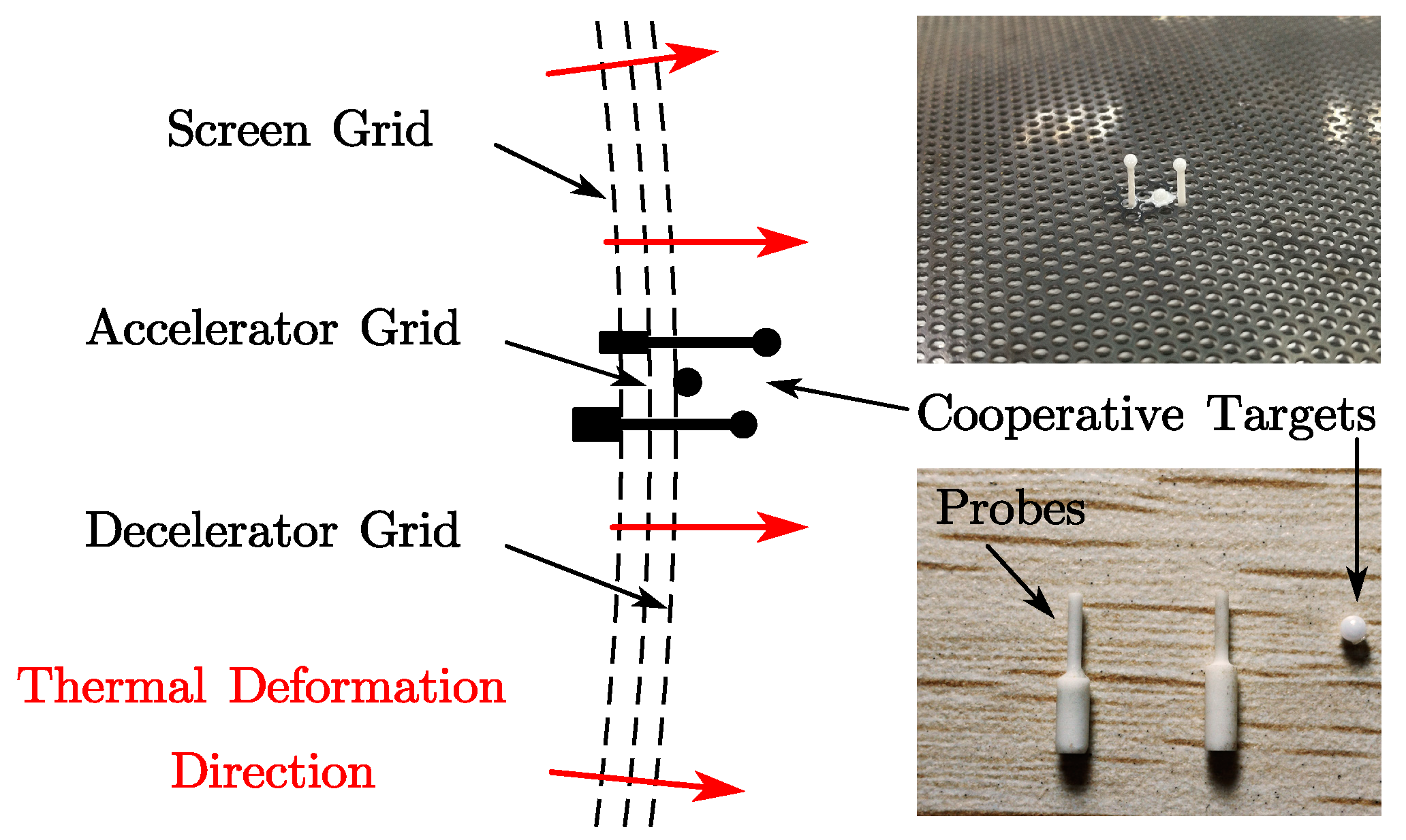
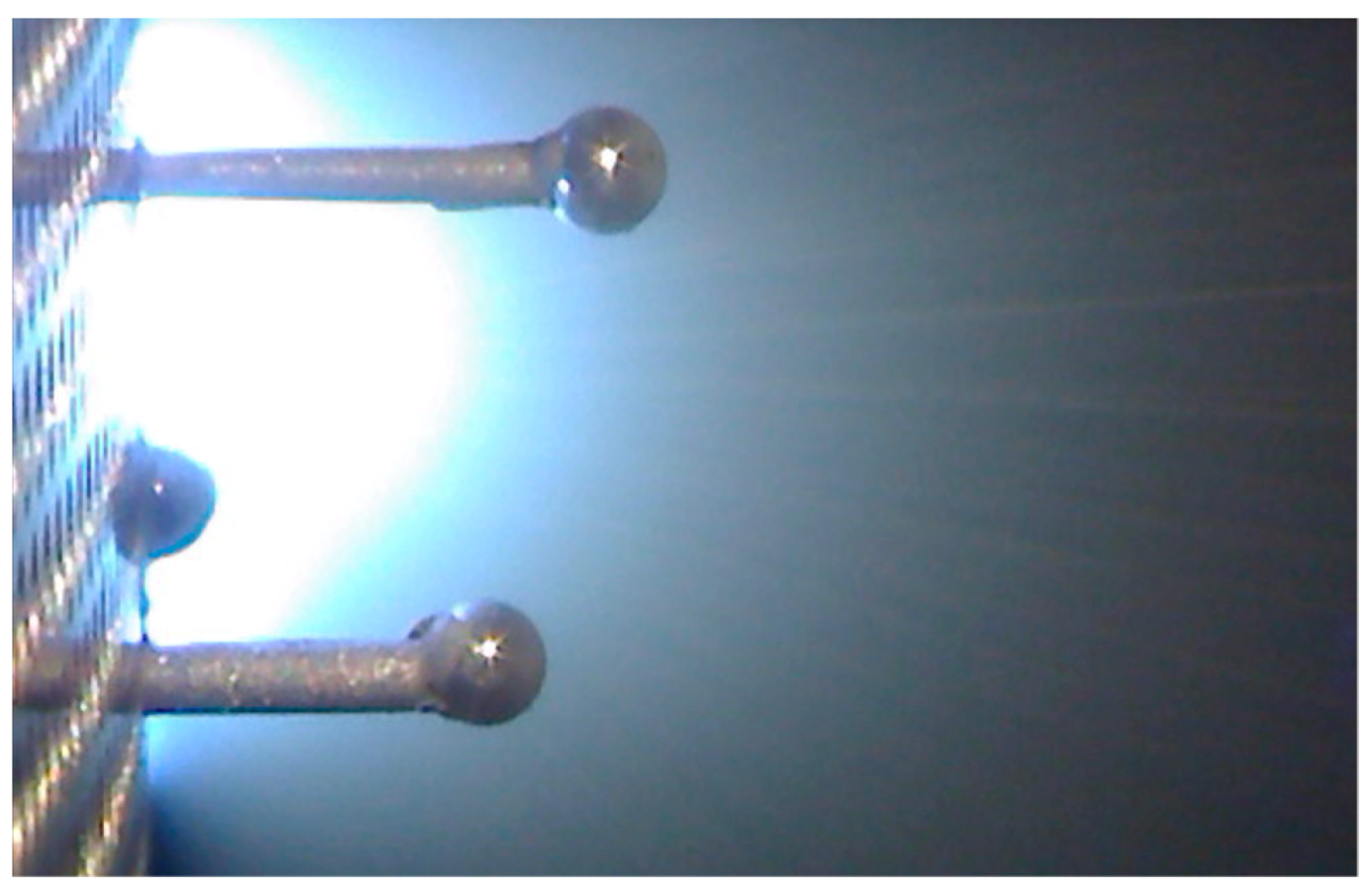
2.1. Measurement Technique

It is difficult to measure ion optics deformation and grid gap variation that are caused by plasma radiation and power deposition, and this paper applies the videometrics measurement method to achieve noncontact measurement of ion optics deformation and grid gap variation. Ion optics works in a vacuum environment accompanied by a high temperature and plasma. In this complex and extreme environment, common thermal deformation measurement methods cannot be used. At the same time, ion optics deformation and grid gap variations are small, so the requirement of measurement accuracy is very high, which is to be in the order of 10 μm. We used a telemicroscope to obtain high-magnification images, and then employed a subpixel image processing algorithm to achieve high-precision measurement of the microdeformation. This noncontact measurement method can avoid grid surface high-temperature effects on the ion optics deformation measurement, and with the protection devices, the measurement system can work properly in vacuum and plasma environments.
The core idea is to install probes and cooperative targets on ion optics and indirectly measure the ion optics deformation by using displacements of the cooperative targets. The cooperative target is a G10 class zirconia sphere with a diameter of 1.5 mm and a precision of 0.25 μm. The probe is an alumina cylinder with a variable diameter structure. As shown in Figure 1, two probes were fixed to the center hole of the screen grid and the accelerator grid, and the cooperative targets were fixed to the center hole of the decelerator grid, and the top of the probes. The probes and the cooperative targets were fixed with high temperature glue. In addition, the probes with a snap structure and thread structure can also be selected in the installation scheme.
Measuring positions were the center of the screen grid, the accelerator grid, and the decelerator grid (maximum deformation of grid). The physical quantities that were measured were the displacements of three cooperative targets. The telemicroscope was mounted on the side of the ion optics through a four-axis precise positioning platform. The devices were adjusted to place the probes and cooperative targets in the middle of the field. The horizontal displacements of three cooperative targets in the field of view represent the thermal deformation of three grids of ion optics. The change in the grid gaps was equal to the difference in thermal deformation of the three grids. When starting the measurement, the serial images collected by the telemicroscope were transmitted to the computer in real time, and the edges of the cooperative targets were extracted by the image processing algorithm. Based on the edge of the cooperative targets, the coordinates of the center of the circle were fitted by the least squares method to accurately locate the cooperative targets, and the image magnification factor and the rotation angle of the coordinate system were also calibrated at the same time. The deformation of the three grids was calculated by the displacements of the cooperative targets, and the variations of the grid gaps were calculated from the difference between the three grids’ thermal deformation in real time.

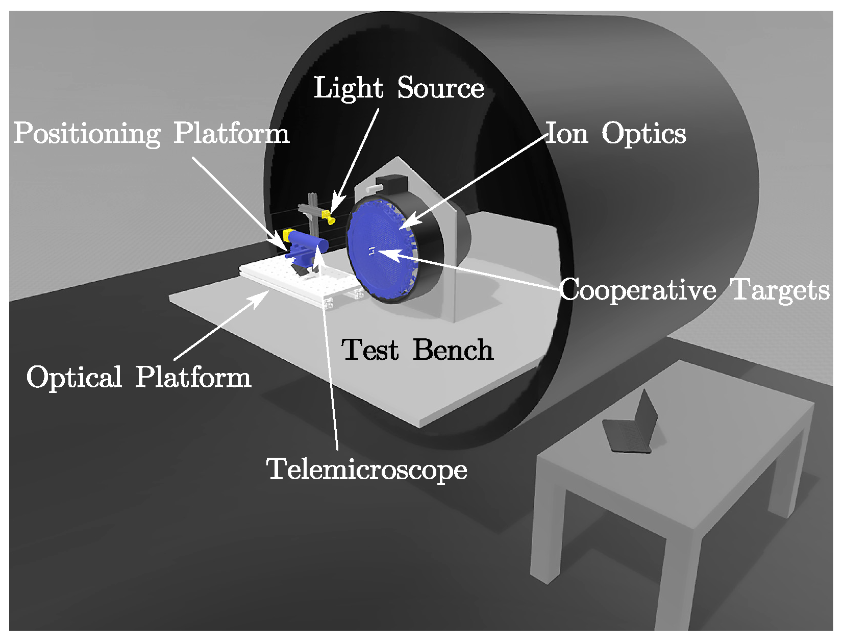
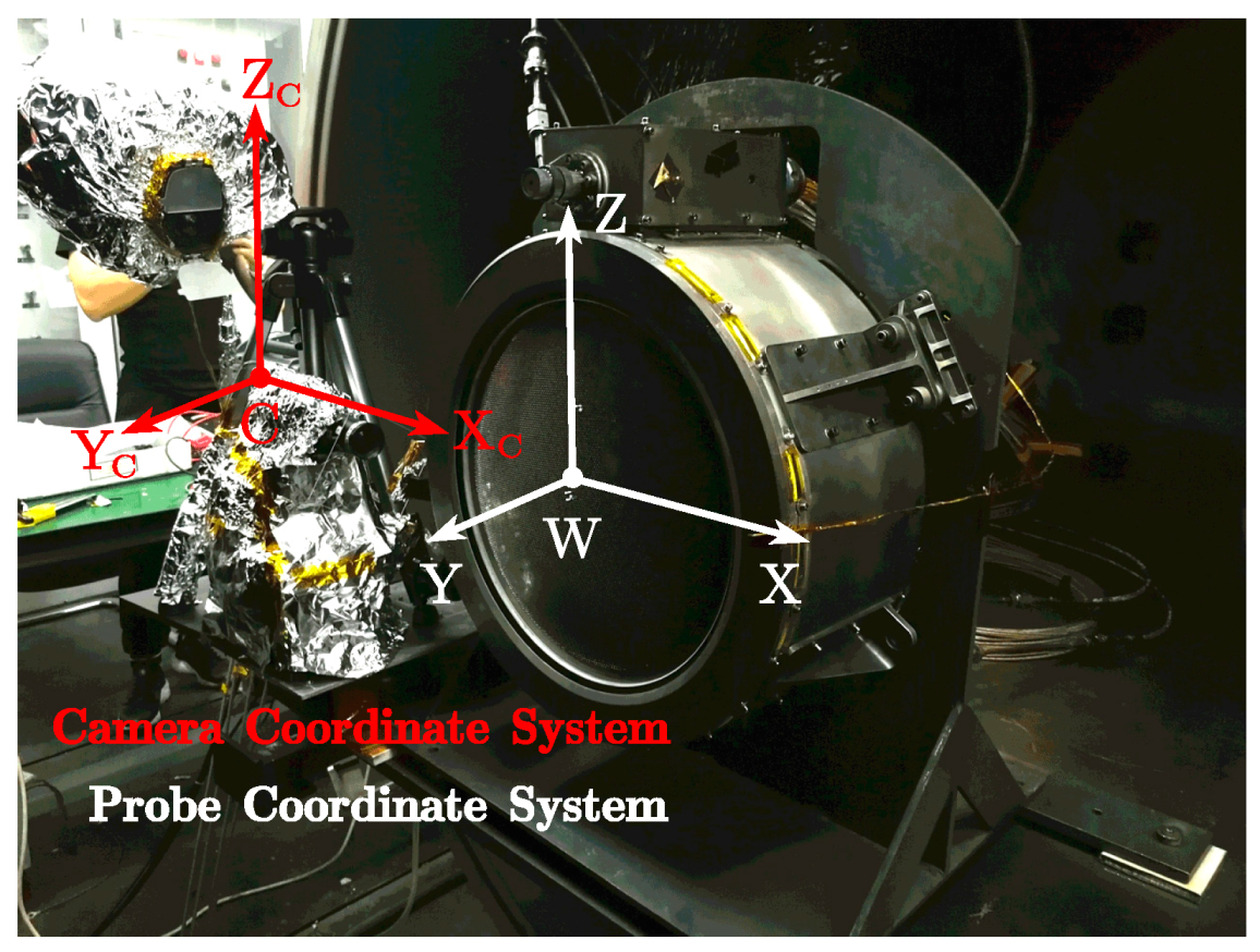
2.2. Hardware Composition

The hardware composition of the system for the vacuum experiment is shown in Figure 2. The system consists of an optical platform, an ion thruster with ion optics, a light source, probes, cooperative targets, a telemicroscope with charge-coupled device (CCD), and a four-axis positioning platform.
The ion optics was fixed on the ion thruster, and the ion thruster was fixed on the test bench and kept perpendicular to the ground. The probes and cooperative targets were mounted in the center of the grids. The LED focusing video light provided a light source that illuminated the probes area. The color temperature range of the LED was 3200–5600 K, and the light angle adjustment range was 15–55°. The telemicroscope lens uses the NAVITAR 12x Zoom Lens System; the CCD telemicroscope image resolution is 1600 pixel × 1200 pixel which can capture 12 frames per second; the sensor chip size is 1/2.5″; and the chip cell size is 2.8 μm × 2.8 μm. The telemicroscope was mounted on a high-precision four-axis positioning platform (three translational degrees of freedom and one rotational degree of freedom), and the position and angle were adjusted so that the telemicroscope’s optical axis and the longitudinal axis of the ion optics were perpendicular (the position accuracy of the linear table was 5 μm and that of the rotation table was 0.1°). The working distance of the telemicroscope lens from the probe was adjusted to 300 mm in the experiment of this paper. Equipment such as video lights and the telemicroscope were installed outside the plasma flow of the grid, with little effect from the plasma beam and high temperature.

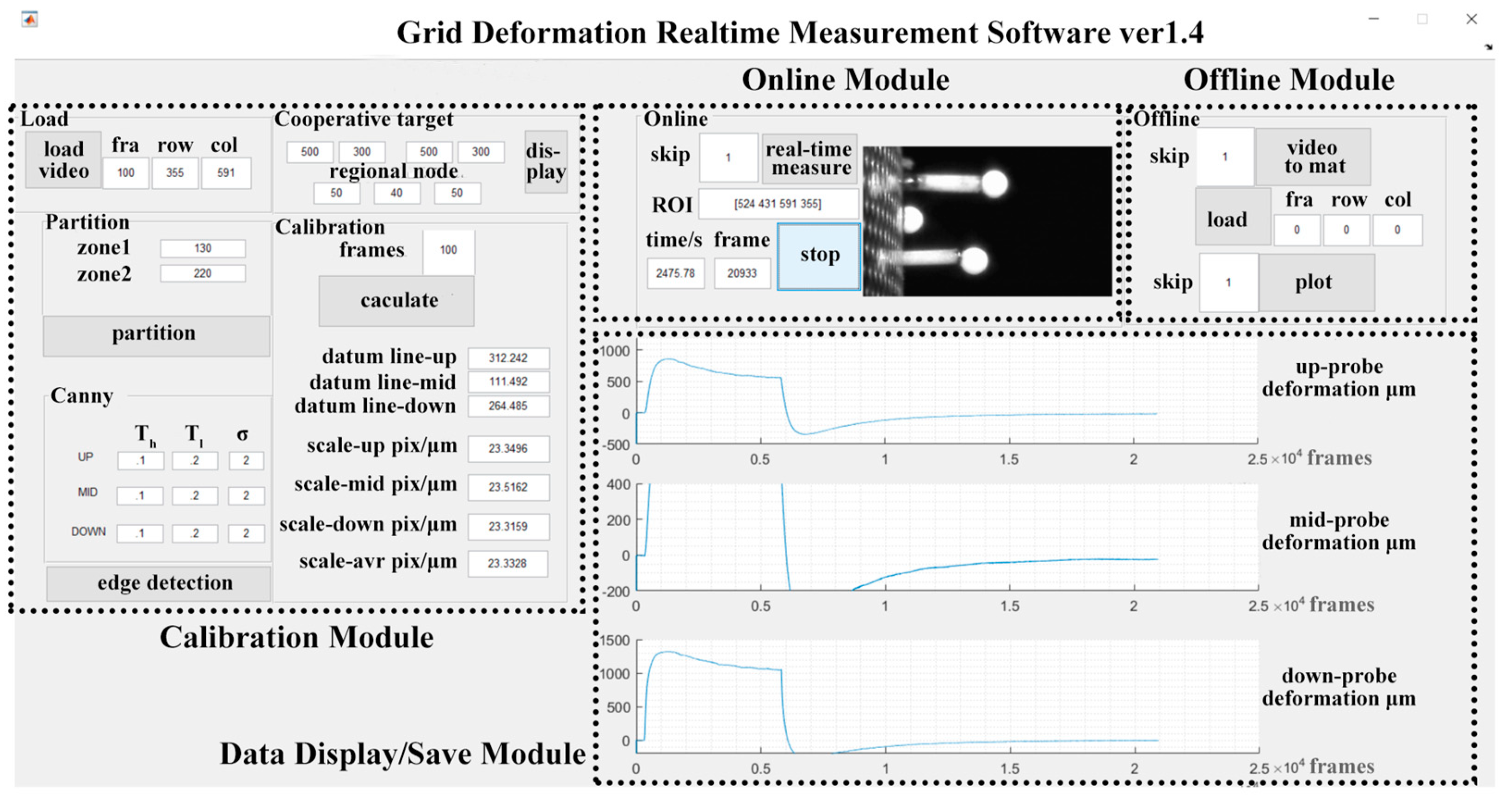
2.3. Software and Test Procedure
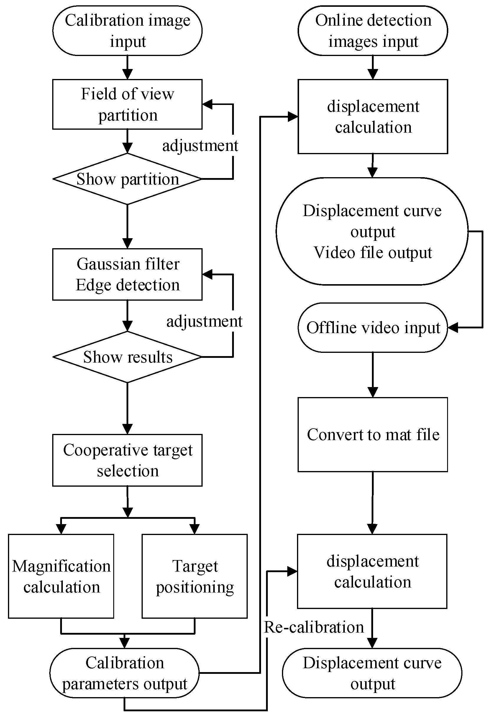
The digital image processing software developed in this paper integrates the functions of image processing, calibration, and displacement calculation of cooperative targets. It can realize real-time measurement, the output of ion optics deformation, and grid gap variation. The measurement software was developed based on MATLAB 2017b and consists of a calibration module, an online measurement module, an offline measurement module, and a data display/save module. The software interface is shown in Figure 3.
The measured data processing flow is shown in Figure 4. Firstly, the telemicroscope was adjusted to place the probes and cooperative targets in the middle of the image, and several frames of images were collected in the calibration module. In the calibration module, the images were partitioned, the edge detection threshold was selected, and edge detection was then executed. The program used the least squares method to fit the center of the cooperative targets as displacement origin and calculated the image magnification factor. Next, the measurement area parameters (region of interest, ROI) and the measurement frequency were inputted to the online detection module; the ion thruster started to operate; and the system continuously measured the ion optics deformation data, and outputted the deformation curve of the screen grid, the accelerator grid, and the decelerator grid in real time. When the ion thruster was shutdown, the deformation of the ion optics during the cooling process was continuously measured until the deformation amount returns to zero. When the measurement is finished, all the collected original image data was saved as a video file. The offline analysis module was used to load the video file, so that the calibration parameters can be adjusted again and so that the related algorithms can be modified to further analyze the thermal deformation of ion optics.

3. Algorithm

The positioning of the cooperative targets and the measurement of their displacements are the core issues of this measurement method. Through the interactive partitioning edge detection method (IPEDM), the stability of the edge detection of the cooperative targets was ensured. The circular cooperative targets, the subpixel positioning, the image magnification factor calibrating, and the rotation angle calibrating ensure the accuracy of the ion optics deformation measurement.

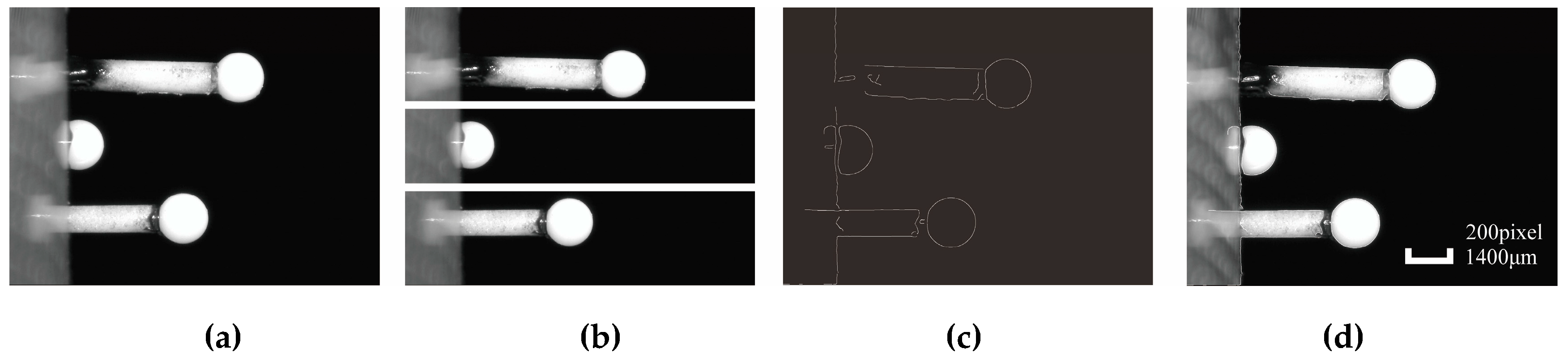
3.1. Image Preprocessing

The Canny operator is the best stability edge detection operator. The algorithm of Canny firstly smooths the image using a Gaussian function, then calculates the gradient magnitude and direction of the grayscale, applies nonmaxima suppression to the gradient magnitude image to determine the edge, and finally uses double thresholding and connectivity analysis to process and connect the edges [22]. The Canny operator has three parameters to control the edge detection. The standard deviation σ of the Gaussian function determines the detection scale of the operator. The smaller the σ , the smaller the detection scale, and finer the edges of the response. The low threshold T L and the high threshold T H in double thresholding are used to reduce false edge points: pixels with a gray level higher than T H are considered strong edges (effective edges); pixels between T L and T H are considered weak edges, which are used to connect and supplement the strong edges; and pixels below T L are considered to be false edges and are set to zero.
Although the Canny operator has a flexible and stable detection performance, there are limitations. For example, after the parameters of the Canny operator are adjusted, the edges of the object can be clearly detected, but it is not possible to detect multiple objects with large differences in gray value at the same time. Fixed Canny parameters cannot accurately detect the edges of multiple objects in one image. This paper proposes an IPEDM based on the Canny operator, which uses Gaussian filtering and double thresholding of different parameters for the three parts of the image. The parameter selection is realized by the software interaction interface. According to the detection results, the Gaussian function standard deviation and the high and low thresholds of each region are adjusted, respectively, so that the three regions can achieve the best edge detection effects.
The field of view is divided into upper, middle, and lower parts, as shown in Figure 5b. The cooperative target of the accelerator grid is located in the upper area, the cooperative target of the decelerator grid is located in the middle area, and the cooperative target of the screen grid is located in the lower area. There is only a single detection target in each area, which allows parameter adjustments to be made for a single target for clearer detection.

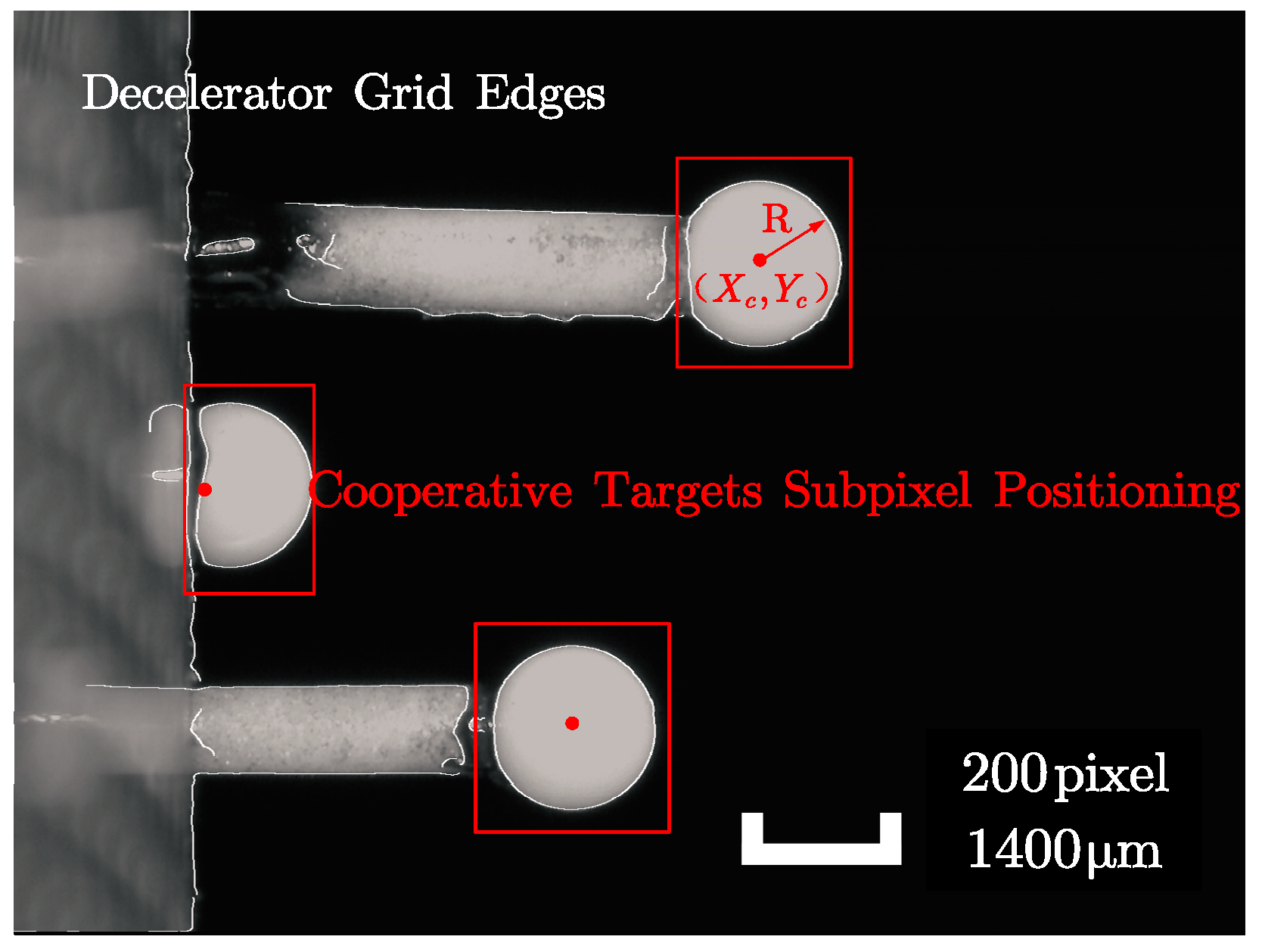
3.2. Targets Positioning and Calibration of Magnification Factor

Based on the interactive partitioning edge detection method, clear edge pixels of the circular cooperative targets were obtained, and precision was achieved at the whole pixel level, as shown in Figure 5c. In order to improve the positioning accuracy of the cooperative targets, the edge pixels of the cooperative targets were extracted, and the coordinates of each pixel were brought into the standard circular equation Equation (1). The least squares method was used to solve Equation (2) and get the three unknown parameters of the circular equation. The center coordinates and the radius value were calculated by Equation (3), the cooperative targets were located based on the center coordinates, and the positioning precision reached the subpixel level, as shown in Figure 6.
x i 2 + y i 2 + a x i + b y i + c = 0   ( x i , y i ) , i = 1 , 2 , 3
M i n Q ( a , b , c ) = i = 1 n [ ( X i 2 + Y i 2 + a X i + b Y i + c ) ] 2
X c = a 2 , Y c = b 2 , R = a 2 + b 2 4 c 2
The calculation of the magnification factor was based on the circular cooperative targets, which were the zirconia sphere of diameter d ¯ = 1.5 mm with an accuracy of G10 class ( a = 0.25 μm). The diameter of the zirconia sphere was evaluated by the class-B uncertainty. Under the confidence level of P = 0.954 , k 1 = 2 , the diameter of the sphere was assumed to be a triangular distribution k 2 = 6 , and the diameter of the sphere was calculated by Equation (4). d real = 1500   ±   0.204 μm.
d real = d ¯   ±   U d = d ¯   ±   k 1     u B ( d ¯ ) = d ¯   ±   k 1     a k 2
The pixel radius measurements of the cooperative targets were calculated on the n = 100 frame images and the result was evaluated by the class-A uncertainty. At the confidence level of P = 0.954 , k 1 = 2 , and the pixel radius was calculated by Equation (5). r pixel = 106.914   ±   0.02 pixel.
r pixel = r ¯   ±   U r = r ¯   ±   k 1     u A ( r ¯ ) = r ¯   ±   k 1     1 n ( n 1 ) i = 1 n ( r i r ¯ ) 2
The magnification factor λ was calculated from the uncertainty transfer formula Equation (6), where λ = 7.0194   ±   0.00162 μm/pixel.
λ = d r e a l 2 r p i x e l = d ¯ r ¯   ±   d ¯ r ¯     ( U d d ¯ ) 2   +   ( U r r ¯ ) 2

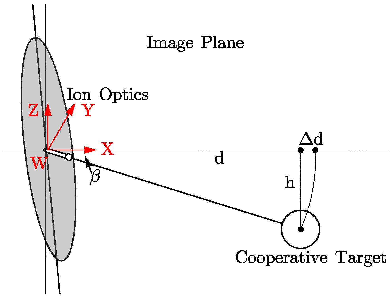
3.3. Calibration of Rotation Angle in the Coordinate System

If the X-axes of the camera coordinate system and the probe coordinate system are not projected parallel in the XY-plane due to the angle error caused by the installation of the camera or the ion thruster, the displacement direction of the cooperative target will not be perpendicular to the optical axis of the camera and the measurement result will contain errors. The camera coordinate system needs to rotate A Z around the Z-axis to make the projection of the X-axis of the two coordinate systems parallel. Similarly, if the camera coordinate system needs to rotate A Y around the Y-axis to make the Z-axis projection of the two coordinate systems parallel, then the camera imaging picture as a whole will produce an angle, resulting in errors in the measurement results. However, for two-dimensional measurement, the rotation angle A X around the X-axis has little effect on the measurement, because the projection of probes and spherical cooperative targets on the two-dimensional image will not change with A X . The camera coordinate system and the probe coordinate system (i.e, the world coordinate system) are shown in Figure 7.
The measurement errors caused by rotation angle A Z are shown in Figure 8. Suppose the deflection angle of the displacement direction is α , the radius of the cooperative target r 0 and the radius after the movement r 1 will appear distorted Δ = r 1     r 0 , and the lateral displacements of the cooperative targets will exhibit an error Δ d . If the deflection angle α is known, the displacement direction of the cooperative targets can be corrected to be perpendicular to the optical axis of the telemicroscope by angular projection transformation, and the distortion can be eliminated.
The following presents a calibration method of deflection angle α with a circular cooperative target. Using the pinhole imaging model’s triangle similarity principle, we can get Equation (7), where R is the actual radius of the cooperative target, u 0 is the object distance before the move, r 0 is the pixel radius of the cooperative target before the move, u 1 is the object distance after the move, r 1 is the pixel radius of the cooperative target after the move, the focal length is f , and the sensor chip cell size is c = 2.8   μ m / pixel .
R   u 0 = r 0 c f ,   R   u 1 = r 1 c f
The initial object distance   u 0 and the object distance after the movement   u 1 can be calculated by Equation (8) or Equation (9).
u 1 = r 0 u 0 r 1
u 1 = f R r 1 c ,   u 0 = f R r 0 c
Then the deflection angle α can be calculated by Equation (10) or Equation (11).
α = arctan Δ u d = arctan u 0 ( r 1 r 0 ) r 1 d c
α = arctan Δ u d = arctan f R ( r 1 r 0 ) r 0 r 1 d c 2
The corrected displacement value d r e a l α is calculated by Equation (12) using the displacement deflection angle α and the displacement d .
d r e a l α = d   +   Δ d = d cos α
The measurement errors caused by rotation angle A Y are shown in Figure 9. If the grids and probes are not perpendicular and level to the horizontal plane, respectively, the measured value will also produce errors with the actual value. The angle β needs to be corrected. If the probe moves at an angle β with the horizontal plane, then after the lateral displacement d is generated, the circular cooperative target will produce a longitudinal displacement h , and the measurement error appears to be Δ d . The corrected displacement value d r e a l β can be calculated by the triangle relationship Equation (13).
d r e a l β = d cos β
Combining errors caused by the deflection angle α and β , the total correction of the cooperative target displacement is d r e a l α , β .
d r e a l α , β =   d cos β cos α

4. Experiment

The measurement experiment of the thermal deformation of ion optics was carried out in the TS-7 vacuum chamber of the Lanzhou Institute of Physics. As shown in Figure 10, the TS-7 vacuum chamber had a variable diameter cylindrical shape, where the main chamber had the radius R = 1900 mm, the length L = 8500 mm, the sub-chamber radius R = 750 mm, and the length L = 1500 mm [23]. It used graphite as the bulkhead lining material, and the background sputter deposition amount was 0.20   μ m / kh . The base pressure was better than 5.0 × 10 5   Pa , and the working pressure was better than 3.5 × 10 3   Pa [24,25]. The experiment used the LIPS-300 thruster with the three-grid ion optics. The ion optics deformation real-time measurement system was working during the actual running conditions of the LIPS-300 thruster.

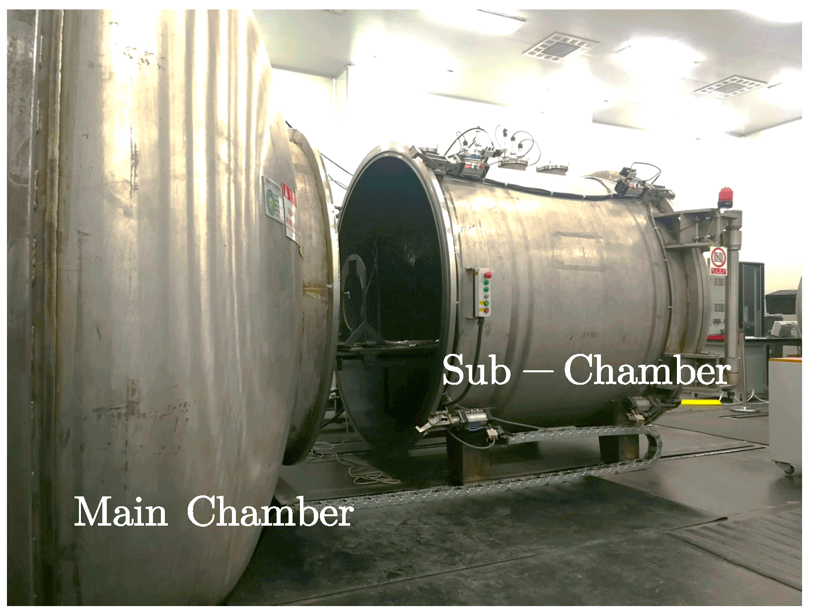
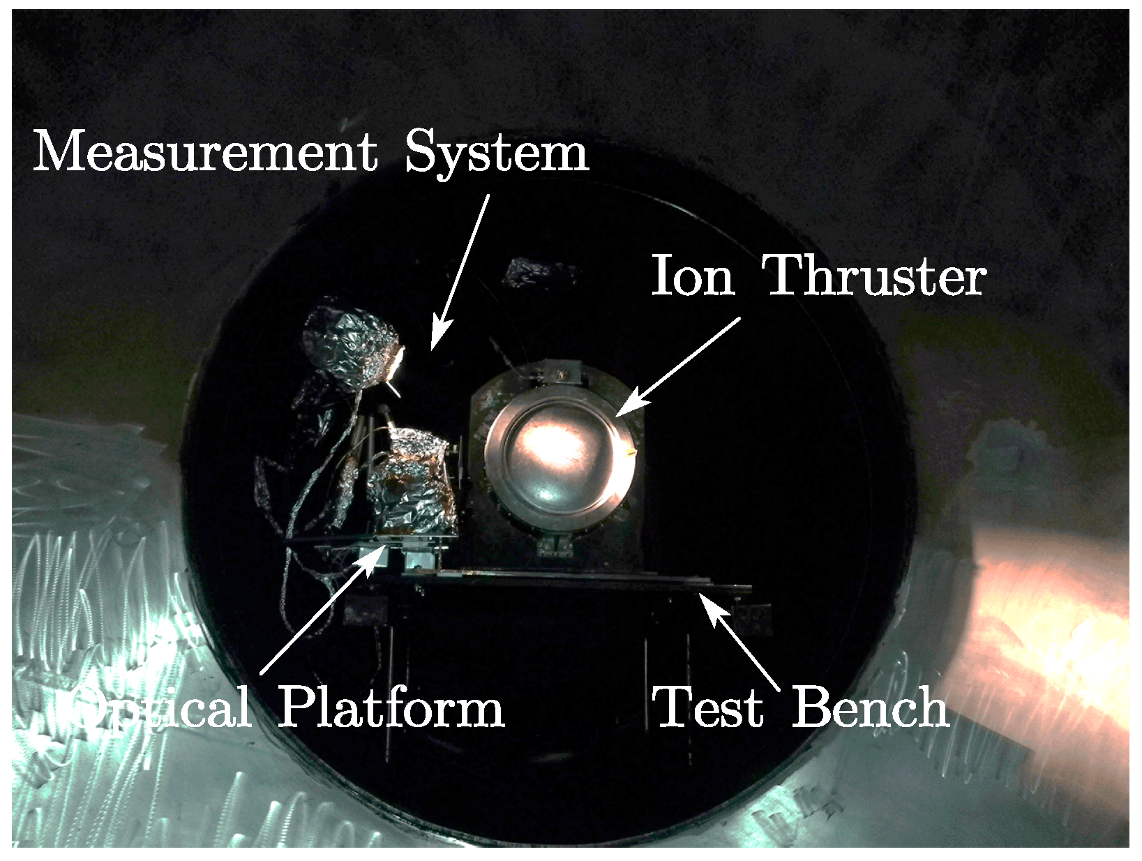
4.1. Equipment Installation and Running Conditions

The ion thruster and ion optics deformation measurement system were mounted on the test bench in the sub-chamber of the TS-7. The optical platform of the ion optics deformation measurement system was connected to the test bench using insulating ceramic plates and insulating bolts to ensure that the measurement system and the ion thruster were insulated from each other. A four-axis high-precision positioning platform was mounted on the optical platform, and a telemicroscope was mounted on the positioning platform. The working distance of the telemicroscope lens from the probe was adjusted to 300 mm. An LED video light was mounted above the telemicroscope to illuminate the probe area evenly. When conducting experiments, there was a plasma beam in the environment, and the measuring equipment had to be properly protected. The beam angle of the ion thruster was about 70°, the measuring device was installed outside the beam range, and the plasma beam did not directly impact the device. Therefore, the measuring device was wrapped with tin foil to prevent ion sputtering in the environment. The telemicroscope lens was the key equipment of the measurement system and was also the closest device to the ion thruster. In order to protect the lens from ion sputter corrosion and plasma coating, quartz glass with a thickness of 1 mm and an area of 10   mm   ×   10   mm was installed in front of the lens, as shown in Figure 11.
The running conditions of the ion thruster were numbered VA-1 and VA-2, as shown in Table 1. The power of the discharge chamber P d was calculated by multiplying the current and voltage of the anode in the discharge chamber. The beam power P b was calculated by the product of the screen grid current and voltage. The total power of the thruster can be approximately equal to the sum of P d and P b .
VA-1 was the discharge chamber pretreatment, in which xenon gas was introduced into the discharge chamber for ionization to form a stable plasma, but the ion optics did not add an electric field, and there was no beam extraction. The maximum power of the discharge chamber was 750 W. If the beam was extracted under this condition, the total power of the thruster was about 5 kW.
VA-2 was the ion optics pretreatment, that is, in the case of the discharge chamber operation, the ion optics was applied with an electric field, and the positive ions in the discharge chamber were extracted and accelerated by the Coulomb force to form a beam. In the experiment, the thruster was operated in the order of small to large power levels and the first four levels were measured.

4.2. VA-1 Experiment Results

In the VA-1 experiment, after the discharge chamber began to ionize, the screen grid, the accelerator grid, and the decelerator grid were deformed, respectively. After 5.3 min of startup, the gaps between the grids were reduced by 420 μm (between the screen and accelerator) and 430 μm (between the accelerator and decelerator), respectively. After 7.3 min of startup, the thermal deformation of the grids reached its maximum value. The maximum thermal deformation of the screen grid was 1120 μm, of the accelerator grid was 701 μm, and of the decelerator grid was 269 μm, as shown in Figure 12.
After the experiment was carried out for 37 min, the thruster was turned off to start cooling, and the grid gaps and grid thermal deformation amount rapidly changed. The grid deformation amount rapidly decreased and a negative value was generated, and the grid gaps gradually returned to the initial value. During the cooling process, the amount of grid deformation and the gaps changed very slowly. At 52 min, measurement was stopped, and the thermal deformation of the grids had not recovered to the initial value, which required longer recovery, as shown in Figure 12. The measured data at critical time points of the VA-1 experiment are shown in Table 2.

4.3. VA-2 Experiment Results

Ion optics pretreatment contained a series of power levels, and the beam was extracted in each level. The experiment started from the first level of the ion optics pretreatment, the thruster was turned on, the discharge chamber began to ionize, and the ion optics then worked to extract the beam. After running for half an hour under the first power level, the power was increased to enter the second power level and continued to run for half an hour, and the subsequent working conditions were sequentially performed. When the ion optics pretreatment was carried out at the fifth power level (discharge chamber power 370 W, beam power 1950 W), the probes and the cooperative targets had been plated with a metal film by the plasma beam, and the ion optics started to appear frequent short circuit. At this time, the maximum power was forcibly turned on, a serious short circuit was created, and the beam could not be extracted. It was judged that the probes had become a conductor to breakover ion optics. The post-test probes are shown in Figure 13. Short circuit phenomena of the ion optics in the experiment are shown in Figure 14.
In the VA-2 experiment, only the first four levels of grid thermal deformation data were measured, as shown in Figure 15. The thermal deformation of the grids in ion optics pretreatment was less than that of the discharge chamber pretreatment, which indicates that the influence on the temperature and deformation of the grids mainly came from the thermal radiation of the discharge chamber plasma and the plasma deposition effect. The larger the discharge chamber power, the larger the deformation, and the influence of beam power on the grid deformation was relatively small.

5. Discussion

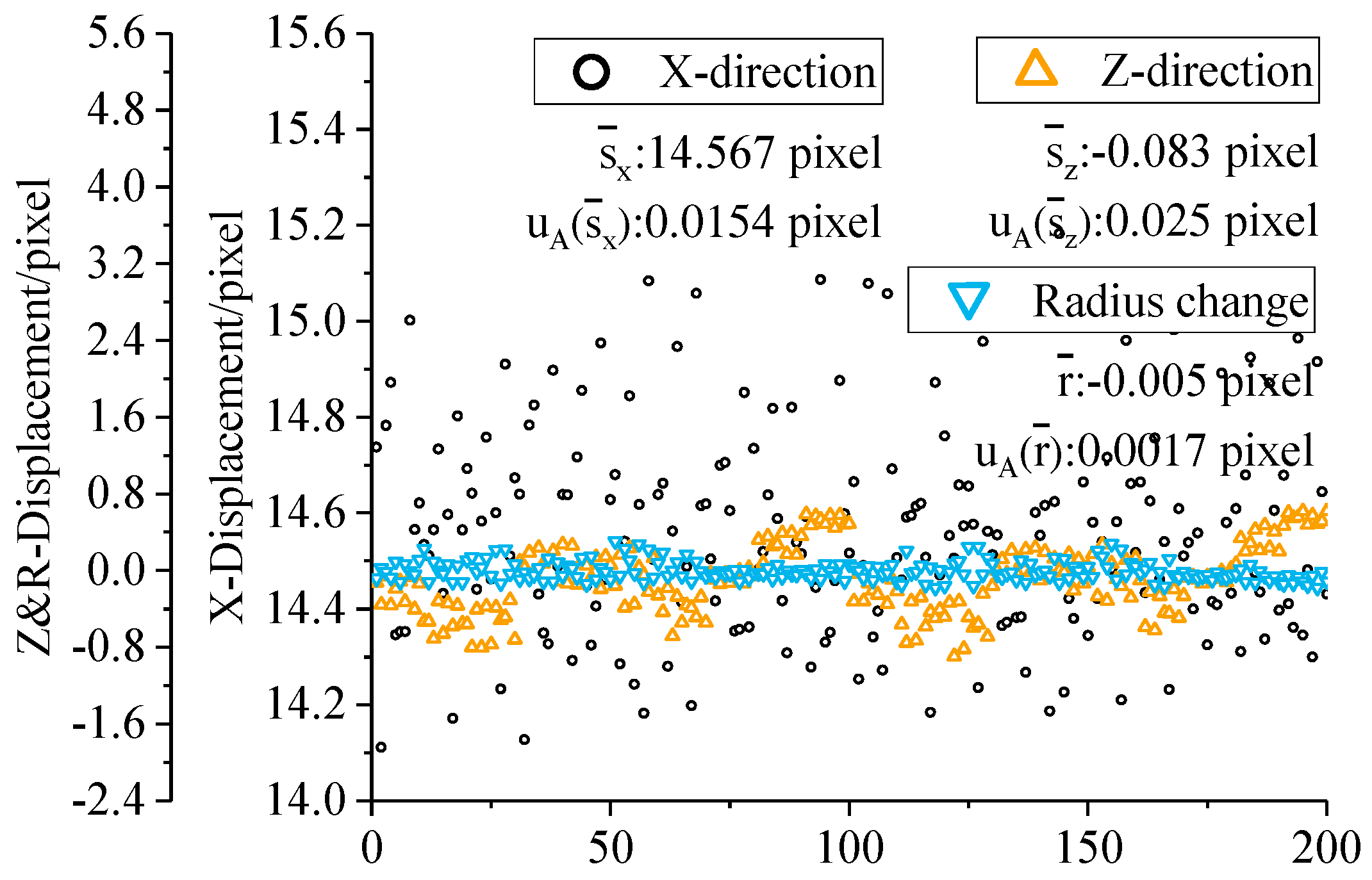
5.1. Analysis of Factors That Affect Accuracy

The main factors affecting the measurement accuracy of the system were the error caused by thermal deformation of the probes, the calibration error of the image magnification factor, and the error caused by the rotation angle of the coordinate system.
The influence of the thermal deformation of probes was mainly due to the measurement error caused by the axial elongation of probes after heating. The linear expansion formula δ = α L Δ T can be used to calculate the axial elongation of the probes as the compensation value. During the working period, the temperature of each section of the probe was different under different working conditions, and the thermal deformation was changing dynamically. The deformation amount of the probes was calculated according to the measured temperature at the time of thermal deformation of the grid [26], and the maximum deformation of the probes is about 6 μm.
The error of the image magnification factor calibrated by the cooperative target was small λ = 7.0194   ±   0.00162   pixel / μ m . In the case where the actual displacement of the cooperative target was 1000 μm, the pixel displacement was about 1000 / 7.02 = 142   pixel , and the error caused by the calibration was only 142   ×   0.002 = 0.28   μ m , which is negligible.
The measurement error caused by the rotation angle was small when the deflection angle was small, and the error was only 0.15 μm when the cooperative target displacement was 1000 μm when the deflection angle was α = 1 ° . In the actual measurement, the deflection angle α can be controlled within 1 ° by adjusting the four-axis high-precision positioning platform, so the error caused by the coordinate rotation angle after adjusting can be neglected.
In addition, the errors caused by lens distortion, the stability of the illumination system, and the coating effect of the plasma beam will also have a greater impact on the measurement, but through a reasonable experimental scheme, they can be avoided.

5.2. Accuracy Assessment of System

The system was in the atmosphere, at room temperature, and the working distance, image magnification factor, and rotation angle were the same as the vacuum experiment. The ion optics was given accurate quantitative displacement through a high-precision positioning platform, which was then measured and verified by the measurement system. The system measures the lateral (X-direction) displacement, the longitudinal (Z-direction) displacement, and the radius change value of the circular cooperative targets in the image. On the four-axis high-precision positioning platform, the X-axis linear table was moved 100 μm with 10 steps, and 10 frames of images were measured each time. The X-axis direction and Z-axis direction displacement amounts and the radius change amounts of each 100 μm move were calculated though the images, and a total of 200 sets of data were obtained as shown in Figure 16.
The Z-axis direction displacements and the radius had no obvious change, indicating no tangential distortion in the image. The pixel displacements of each 100 μm in the image are evaluated as S p i x e l = s ¯ X   ±   2   ×   u A ( s ¯ X ) = 14.567   ±   0.316 pixel in type A evaluation. It is known that the magnification factor calibration result is λ = λ ¯   ±   2   ×   u A ( λ ¯ ) = 7.000448   ±   0.0122 μm/pixel, so the displacement measurement result of the circular cooperation logo is S r e a l = S p i x e l ×   λ = 101.969   ±   0.284   μ m . The displacement of the platform per 100 μm is evaluated with type B evaluation. It is known that the accuracy of the linear table is a = 5 μm; the error of the linear table is a triangular distribution, k 2 = 6 ; and at the confidence level P = 0.954 , k 1 = 2 , D = d ¯   ±   U d = d ¯   ±   k 1   ×   u B ( d ¯ ) = d ¯   ±   k 1 × a k 2 = 100   ±   4.082   μ m . Therefore, the measurement error is δ = S real D = 101.969   ±   0.284 100   ±   4.082 = 1.969   ±   4.092   μ m , and the maximum error is 6.061 μm.
It is necessary to point out that the accuracy of the linear table itself is not high enough, thus the actual measurement accuracy of the system should be better than the calculated value. At the same time, the error of thermal deformation of the probe was taken into consideration, so the measurement accuracy of the system should be better than 12 μm.

5.3. Grids Deformation Characteristics

By comparing the experimental results with NASA experiments on grid thermal deformation [10,13,14], it is found that grid thermal deformation has the following characteristics:
1. During the operation of the thruster, the deformation of the grid and the amount of change in the grid gap are drastically changed in the initial stage of the change of the running conditions. From the thermal deformation curve, it was found that the amount of grid deformation rises rapidly after the thruster starts, reaches a maximum value in a short time, and then slowly decreases. The deformation of the screen grid is greater than that of the accelerator grid, resulting in a decrease in grid gap. The grid gap decreases rapidly after the gate begins to heat up, and after reaching the minimum value, the pitch rises. The grid gap decreases rapidly after startup, and after reaching the minimum value, the grid gap begins to slowly rise;
2. By comparing the experimental data, we can know that the higher the power of the discharge chamber, the higher the grid temperature, and the greater the thermal deformation of the grid. However, the beam power has little effect on the thermal deformation of the grid;
3. In the initial stage, the grid will be severely deformed and the maximum deformation will be achieved. When it tends to be stable, the deformation of the grid will decrease to a stable value. When the heating stops and the cooling starts, the grid deformation will decrease rapidly and negative displacement will occur. All these phenomena are caused by the lag deformation of the grid mounting ring [2,26,27].

6. Conclusions

Based on the demand of ion optics deformation and grid gap measurement, a videometrics method is proposed and a related measurement system is developed. The experiment was carried out in a vacuum environment. The conclusions are as below:
1. The system adopts videometrics measurement and a calibration method based on a cooperative target to realize high-precision and real-time measurement of ion optics deformation and grid gap variation. The system satisfies the requirement of real-time detection in a vacuum, high-temperature, and plasma environment. It can also be used for off-line detection based on videos. It is suitable for the measurement of two- and three-grid ion optics;
2. The thermal deformation of the grid and grid gap are measured under the actual operating conditions of the thruster. At 750 W power of the discharge chamber, the maximum thermal deformation of the screen grid was 1120 μm, of the accelerator grid was 701 μm, and of the decelerator grid was 269 μm. According to the measured results, the thermal deformation characteristics of the grid were preliminarily analyzed;
3. The primary factor affecting the measurement accuracy of the system was the thermal deformation of the probes. The maximum error caused by thermal deformation of the probe was 6 μm, and the accuracy assessment result showed that the measurement error of the system is better than 12 μm.

Author Contributions

Conceptualization, J.Y., D.L., and S.Z.; methodology, J.Y., D.L., and S.X.; software, D.L. and S.X.; validation, P.D.; formal analysis, D.L., S.Z.; investigation, J.Y., D.L., S.Z.; resources, J.Y., P.D.; data curation, D.L., X.L.; Writing—Original Draft preparation, J.Y., P.D., D.L.; Writing—Review and Editing, D.L.; supervision, J.Y.; project administration, J.Y.; funding acquisition, P.D.

Funding

This research was funded by the National Key Laboratory Open Fund of Vacuum and Cryogenic Technology on Physics in the Lanzhou Institute of Physics (No. ZWK1702), and The APC was funded by College of Aerospace Science and Engineering, National University of Defense Technology.

Acknowledgments

The authors are grateful for their homeland’s nourishment and support.

Conflicts of Interest

The authors declare no conflict of interest.

References

  1. SUN, M.; Jia, Y.; Huang, Y.; Yang, J.; Wen, X.; Wang, M. Study on the influence of three-grid assembly thermal deformation on breakdown times and an ion extraction process. Plasma Sci. Technol. 2018, 20, 65509. [Google Scholar] [CrossRef]
  2. Soulas, G.C. Calculation of Thermally-Induced Displacements in Spherically Domed Ion Engine Grids. In Proceedings of the 29th International Electric Propulsion Conference, Cleveland, OH, USA, 31 October–4 November 2005. [Google Scholar]
  3. Kaufman, H.R. Technology of Electron-Bombardment Ion Thrusters. Adv. Electron. Electron Phys. 1975, 36, 265–373. [Google Scholar]
  4. Rawlins, V.K.; Banks, B.A.; Byers, D.C. Design, fabrication, and operation of dished accelerator grids on a 30-cm ion thruster. In Proceedings of the 9th Electric Propulsion Conference, Cleveland, OH, USA, 17–19 April 1972. [Google Scholar] [CrossRef]
  5. Wirz, R.; Katz, I.; Goebel, D.; Anderson, J. Electron Backstreaming Determination for Ion Thrusters. In Proceedings of the 44th AIAA/ASME/SAE/ASEE Joint Propulsion Conference, Hartford, CT, USA, 21–23 July 2008; pp. 206–210. [Google Scholar]
  6. Chen, M.; Xia, G.; Xu, Z.; Mao, G. Analysis on the effects of optics thermal deformation on the ion thruster operation. Acta Phys. Sin. 2015, 9, 283–289. (In Chinese) [Google Scholar]
  7. Farnell, C.C. Performance and lifetime simulation of ion thruster optics. Ph.D. Thesis, Colorado State University, Fort Collins, CO, USA, 2007. [Google Scholar]
  8. Van Noord, J.L. Lifetime Assessment of the NEXT Ion Thruster. In Proceedings of the 43rd AIAA/ASME/SAE/ASEE Joint Propulsion Conference & Exhibit, Cincinnati, OH, USA, 8–11 July 2007. [Google Scholar]
  9. Soulas, G.C.; Shastry, R. Post-test Inspection of NASA’s Evolutionary Xenon Thruster long duration test hardware: ion optics. In Proceedings of the 52nd AIAA/SAE/ASEE Joint Propulsion Conference, Salt Lake City, UT, USA, 25–27 July 2016. [Google Scholar]
  10. MacRae, G.S.; Zavesky, R.J.; Gooder, S.T. Structural and thermal response of 30 cm diameter ion thruster optics. In Proceedings of the 25th Joint Propulsion Conference, Monterey, CA, USA, 12–16 July 1989. [Google Scholar]
  11. Pollard, J.; Welle, R. Thrust vector measurements with the T5 ion engine. In Proceedings of the 31st Joint Propulsion Conference and Exhibit, San Diego, CA, USA, 10–12 July 1995. [Google Scholar]
  12. Trava-Airoldi, V.J.; Garner, C.; Pivirotto, T.; Brophya, J. An optical technique to measure ion engine grid distortion due to differential thermal expansion. In Proceedings of the 21st International Electric Propulsion Conference, Orlando, FL, USA, 18–20 July 1990. [Google Scholar]
  13. Soulas, G.C.; Frandina, M.M. Ion Engine Grid Gap Measurements. In Proceedings of the 40th Joint Propulsion Conference and Exhibit, Fort Lauderdale, FL, USA, 11–14 July 2004. [Google Scholar]
  14. Diaz, E.M.; Soulas, G.C. Grid Gap Measurement for an NSTAR Ion Thruster. In Proceedings of the 29th International Electric Propulsion Conference, Cleveland, OH, USA, 31 October–4 November 2005. [Google Scholar]
  15. Bundesmann, C.; Tartz, M.; Scholze, F.; Neumann, H.; Leiter, H.J.; Scortecci, F. In Situ Thermal Characterization of the Accelerator Grid of an Ion Thruster. J. Propul. Power 2011, 7, 532–537. [Google Scholar] [CrossRef]
  16. Bundesmann, C.; Eichhorn, C.; Scholze, F.; Spemann, D.; Neumann, H.; Pagano, D.; Scaranzin, S.; Scortecci, F.; Leiter, H.J.; Gaute, S.; et al. An advanced electric propulsion diagnostic (AEPD) platform for in-situ characterization of electric propulsion thrusters and ion beam sources. Eur. Phys. J. D 2016, 70, 1–11. [Google Scholar] [CrossRef]
  17. Misuri, T.; Vrebosch, T.; Pieri, L.; Andrenucci, M.; Tordi, M.; Marcuzzi, E.; Bartolozzi, M.; Renzetti, S.; Del Amo, J.G. Telemicroscopy and Thermography Diagnostic Systems for Monitoring Hall Effect Thrusters. In Proceedings of the 32nd International Electric Propulsion Conference, Wiesbaden, Germany, 11–15 September 2011. [Google Scholar]
  18. Misuri, T.; Andrenucci, M.; Vrebosch, T.; Tordi, M.; Marcuzzi, E.; Bartolozzi, M.; del Amo, J.G. Advanced Erosion Diagnostics for Hall Effect Thrusters and Gridded Ion Engines. In Proceedings of the 47th AIAA/ASME/SAE/ASEE Joint Propulsion Conference & Exhibit, San Diego, CA, USA, 31 July–3 August 2011. [Google Scholar]
  19. Sun, M.; Wang, L.; Yang, J.; Wen, X.; Huang, Y.; Wang, M. Study of the key factors affecting the triple grid lifetime of the LIPS-300 ion thruster. Plasma Sci. Technol. 2018, 20, 45504. [Google Scholar] [CrossRef]
  20. Yu, Q.; Shang, Y. Videometrics: Principles and Researches; Science Press: Beijing, China, 2009; ISBN 978-7-03-024189-4. (In Chinese) [Google Scholar]
  21. Yu, Q.; Lu, H. Image Based Precise Measurement and Motion Measurement; Science Press: Beijing, China, 2002. (In Chinese) [Google Scholar]
  22. Gonzalez, R.C.; Woods, R.E. Digital Image Processing, 3rd ed.; Prentice-Hall, Inc.: Upper Saddle River, NJ, USA, 2007. [Google Scholar]
  23. Zhang, T.; Tian, H.; Chen, J. A Study of LIPS-200 Ion Thruster Life Test on Ground. Spacecraft Eng. 2012, 4, 111–116. (In Chinese) [Google Scholar]
  24. Zhang, T.; Chen, J.; Li, X.; Chen, J. Calculation of backsputter depositon on LIPS-200 ion thruster in the life test. Spacecraft Environ. Eng. 2011, 5, 436–439. (In Chinese) [Google Scholar]
  25. Zhao, Y.; Zhang, T.; Huang, Y.; Sun, X.; Sun, Y.; Li, J.; Yang, F.; Chi, X. Experimental Study of 40cm Ion Thruster over a Wide Range of Input Power. J. Propul. Technol. 2018, 39, 942–947. (In Chinese) [Google Scholar]
  26. Liang, D. Research on On-line Videometrics Measurement System for Thermal Deformation of Ion Thruster Optics. Master’s Thesis, National University of Defense Technology, Changsha, China, December 2018. [Google Scholar]
  27. Rawlins, V.K.; Banks, B.A.; Byers, D.C. Dished Accelerator Grids on a 30-cm Ion Thruster. J. Spacecraft Rockets 1973, 10, 29–35. [Google Scholar] [CrossRef]
Figure 1. The installation of probes and cooperative targets.
Applsci 09 01759 g001
Figure 2. The grid deformation real-time measurement system.
Applsci 09 01759 g002
Figure 3. The ion optics hot gap measurement software.
Applsci 09 01759 g003
Figure 4. The flow chart of the analysis of the measured data.
Applsci 09 01759 g004
Figure 5. Image division and edge detection: (a) Telemicroscope imaging, (b) division of the image, (c) edge detection results, and (d) final test result view.
Applsci 09 01759 g005
Figure 6. The subpixel positioning of cooperative targets.
Applsci 09 01759 g006
Figure 7. The camera coordinate system and the probe coordinate system.
Applsci 09 01759 g007
Figure 8. Error correction of X-axis rotation angle.
Applsci 09 01759 g008
Figure 9. Error correction of Y-axis rotation angle.
Applsci 09 01759 g009
Figure 10. The TS-7 vacuum chamber of the Lanzhou Institute of Physics.
Applsci 09 01759 g010
Figure 11. The installation of equipment in the vacuum chamber.
Applsci 09 01759 g011
Figure 12. The VA-1 vacuum experiment grid thermal deformation data. (a) Heating period data. (b) Cooling period data.
Applsci 09 01759 g012
Figure 13. The post-test probes.
Applsci 09 01759 g013
Figure 14. The short circuit phenomena of the ion optics.
Applsci 09 01759 g014
Figure 15. The VA-2 vacuum experiment grid thermal deformation data. (a) Level 1 data, (b) Level 2 data, (c) Level 3 data, and (d) Level 4 data.
Applsci 09 01759 g015
Figure 16. The system accuracy dynamic verification results.
Applsci 09 01759 g016
Table 1. The running conditions of the ion thruster.
Running ConditionsNo. Discharge   Chamber   Power   P d Beam   Power   P b Memo
Discharge chamber pretreatmentVA-1750 W0 WRunning for 1 h, cool down
Ion optics pretreatment level 1VA-280 W250 WRunning for 0.5 h, increase power
Ion optics pretreatment level 2150 W480 WRunning for 0.5 h, increase power
Ion optics pretreatment level 3185 W640 WRunning for 0.5 h, increase power
Ion optics pretreatment level 4200 W1080 WRunning for 0.5 h, increase power
Table 2. The measured data at critical time points of the VA-1 experiment.
No.Time (min)Deformation (mm)Memo
Decelerator GridAccelerator Grid Screen GridGap S-AGap A-D
VA-1 00.020.020.0200Start
5.30.250.681.09− 0.41− 0.43Gap min
7.30.270.701.12− 0.42− 0.43Deformation max
37.50.090.470.88− 0.41− 0.38Stop

