1. Introduction
The application of thermal energy storage (TES) combined with conventional power plants and power plants driven by renewable energy sources offer considerable advantages. For conventional power plants, the integration of TES potentially improves the operating flexibility and reduces minimum load, thereby a decrease in operational costs and an increase in power plant system efficiency are prospected. For power plants based on renewable energy, e.g., concentrated solar power (CSP) plants, TES opens up the opportunity to continue operation beyond sunshine hours and to compensate for alternating solar radiation income during daytime. Additionally, technologies like adiabatic compressed air energy storages (ACAES) are based on the application of TES as well. Further applications can be found in steel and glass manufacturing or other industrial processes with large amounts of waste heat, where the heat can be stored in a TES for later recirculation into the process.
For applications with gaseous heat transfer media, regenerator-type heat storages offer cost-effective and straightforward design solutions. In such arrangements, the gaseous heat transfer media, e.g., flue gas or air, flows through a solid storage material, and sensible heat is transferred via direct contact from the heat transfer media to the storage material (charging) or vice versa (discharging). The following paragraph gives an overview of existing regenerator-type heat storage technologies and materials.
Conventionally used solid media energy storage in the steel manufacturing industries consists of fixed bed installations of shaped ceramic bricks or clinkers, which are stacked inside of a container. Depending on specific requirements of the storage application, a variety of different brick sizes and shapes can be utilized. A selection of possible inventory options is shown in
Figure 1. Another important part of the arrangement is the isolation, which is typically installed between the storage material and the inner container wall. There are multiple options of viable isolation materials, e.g., refractory or fire clay bricks. The regenerator is operated by channeling a gaseous heat transfer fluid (HTF) through the storage material. Thermal charging of the storage material is achieved by a hot HTF streaming through the storage material. The flow direction usually is from top to bottom of the arrangement in order to ensure lower temperature at the load-bearing lower part of the container.
In search of cost-efficient inventory material with adequate thermal performance, packed beds of ceramic pebbles or simply of natural stone were identified as promising options. While offering low cost potential (especially in the case of natural stone packed beds), the heat transfer rates are still comparable to shaped bricks installations. While smaller-sized particles increase the thermal efficiency of the packed bed compared to larger particle sizes, they also increase the pressure loss during operation of regenerator-type heat storages. This tradeoff leads to typical particle sizes between 10 mm and 100 mm, depending on the specific application.
However, when used as heat storage material, packed beds lead to a high technical risk for the inventory itself and the encircling containment isolation. This issue is a result of the punctiform inter-particle and particle-isolation contacts, further amplified by cyclic thermal swelling and shrinking of the particles during the thermal charging and discharging process. As a consequence, mechanical and thermo-mechanical loads are induced. Considering thermal cycling on a daily basis and large bed heights, those induced loads might have a severe negative impact on the life expectancy of the storage. Therefore, proper adjustments in container and packed bed design have to be made. For that reason, knowledge of the occurring stresses and loads is essential, which, again, requires appropriate test rigs and simulation tools in order to calculate those loads.
In order to numerically describe packed bed behavior and properties, two basic modelling approaches exist. The first one is based on a discrete system of interacting particles applying forces amongst each other while in contact and thus rearranging themselves within the packed bed. The discrete element method (DEM), introduced by Cundall and Struck [
1], is founded on this approach. Though the DEM enables highly accurate modelling of packed bed behavior, the computing time to solve the multitude of underlying numerical operations for a large number of particles is non-satisfying. The original approach is limited to the computation of pure mechanical forces, however, extensions to the model were developed to consider thermal effects as well [
2]. The other approach is based on a macroscopic perception of the packed bed, assuming homogenous and isotropic material properties and treating the packed bed as a continuous media. Continuum-based finite element models offer a significant speed up in calculation time in comparison to discrete models. However, they require the identification and implementation of various parameters to appropriately model packed bed mechanics. Further information about feasible continuum models and relevant parameters can be gathered from multiple sources [
3,
4,
5].
Key parameters required for a continuum model approach can be identified and determined by a basic test procedure utilized for characterizing soils and granular media [
6]. Thus, Reimann [
7] provided a correlation of the packed bed’s moduli of deformation as a function of temperature and stress for a variety of materials used in ceramic breeder blankets. The correlation is based on experimental data gained from uniaxial compression tests (UCTs) for the investigated materials. In contrast to typical packed beds used in ceramic breeder blankets, possible options in heat storage applications vary in terms of material, size and shape due to different requirements and specifications. Hence new data for specific heat storage material will be presented in this paper.
For simulating thermo-mechanical forces in a large-scale packed bed heat storage with millions of particles, the discrete element method turns out to be unfit due to high computation time. Despite high calculation effort, it is still possible to take advantage of the discrete model approach by utilizing it for the identification of packed bed-specific continuum parameters following Reimann’s approach.
In this paper, a particle discrete model is applied using the DEM for the simulation of UCTs in order to determine the stress-strain characteristics of a selected packed bed. Additionally, a custom-built UCT test rig is introduced. The experimental results are assessed in order to validate the simulation model. Furthermore, the influence of different particle size distributions on the mechanical behavior of the packed bed will be investigated.
2. Experimental Setup
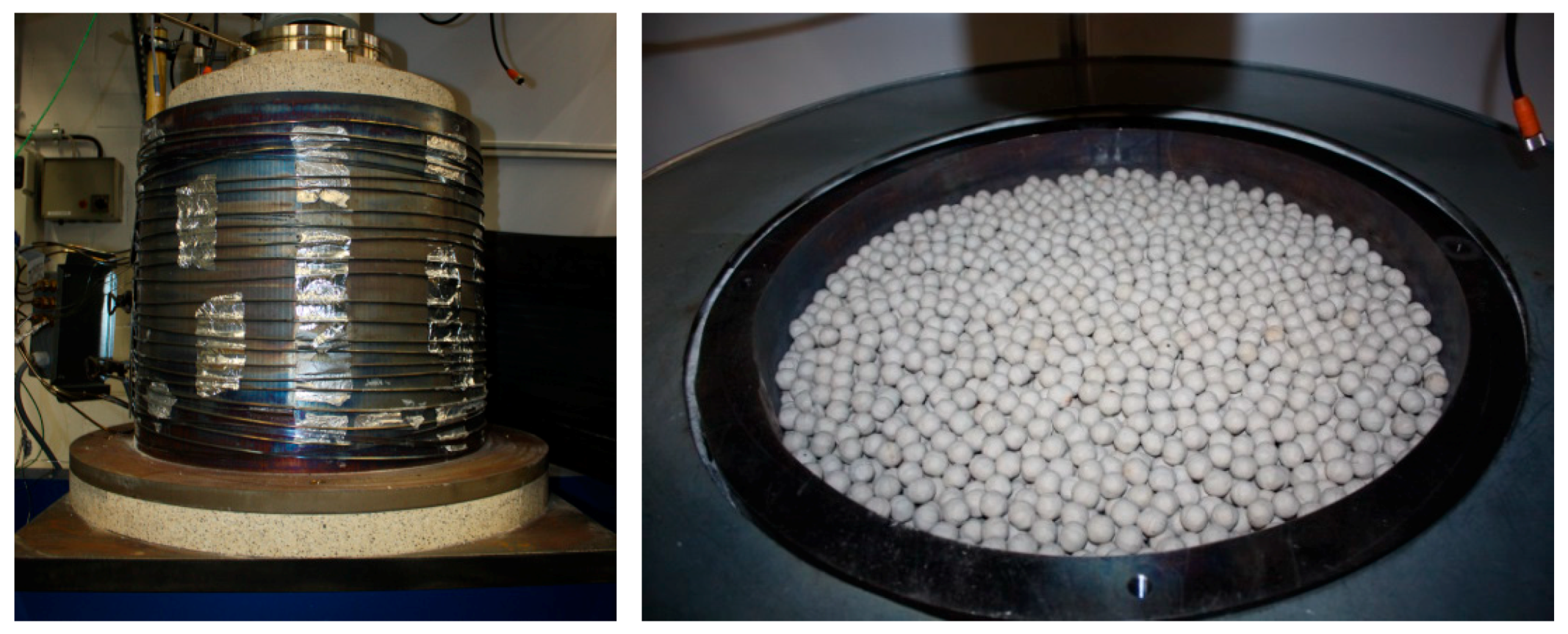
A custom-build test rig for uniaxial compression was set up with the objective of investigating the mechanical properties of a specific packed bed at elevated temperatures and to validate the particle discrete simulation model. The uniaxial compression test rig enabled the compression of a packed bed in a cylindrical container in axial direction, while both the axial pressure and the axial strain of the packed bed were recorded. The stainless steel-made container (
Figure 2) measured 0.5 meters in diameter as well as 0.5 meters in height, which resulted in a maximum filling capacity of 0.098 m
3. Heating wires with a total of 7.5 kW of heating power were wrapped around the outer container wall and allowed for packed bed temperatures up to 600 °C. The container was thermally isolated by using insulation wool of 0.2 m thickness for the cylindrical outer wall. Additionally, two refractory bricks were mounted on top of the cover plate for thermal isolation and to protect the load sensor from high temperatures.
A hydraulic press with a potential of 160 tons of pressure weight was used for mechanical loading. The exerted forces were recorded by a load censor produced by HBM. The axial displacement of bed height was measured by using four laser sensors (manufactured by WAYCON) positioned on top of the cover plate and periodically spread at a 90-degree offset (see
Figure 3).
Technical details on the measurement devices can be found in
Table 1. In order to prevent impairment of measurement precision during operation at elevated temperatures, the measuring instruments were thermally decoupled by ceramic encapsulation. In addition, there was an active cooling system installed on top of the cover plate to reduce the temperature at the contact point of the punching tool and the cover plate.
The test procedure starts with the filling of the selected packed bed into the pressure cell, followed by the positioning of the cover plate on top of the packed bed. For testing at elevated temperatures, the packed bed is heated by the heating wires until isothermal conditions inside of the packed bed are reached. Afterwards, pressure is applied stepwise on the cover plate until a predefined strain is reached. After that, the pressure is kept at a constant level for 15 seconds. The test procedure continues with the reversed sequence as the packed bed is decompressed by subsequently releasing the pressure from the cover plate. These compression-decompression cycles are repeated six times and the test run is completed. After each completed test run, the pressure cell is refilled with a new packed bed batch for a new test run. The substantial material properties of the investigated packed bed are listed in
Table 2.
The given particle size was chosen in order to be representative of typical particle sizes for large-scale applications in the range of 10 mm to 100 mm, while still ensuring a sufficient number of particles over the length and height of the test rig. The particle size distribution of the utilized pebbles was nearly uniform, with small variances due to the fabrication process. While the Young’s modulus of the bulk material significantly changed at elevated temperature, the temperature dependencies of the other material properties can be neglected.
3. Discrete Element Method
The DEM is a technique to compute forces between interacting particles and the resulting displacement. Though originally this method was applied in the field of molecular dynamics, the DEM increasingly evolved to become an important tool for simulating the behavior of macroscopic particles. It is based on a discrete implementation of a multitude of individual particles, in which each particle contact is represented as a friction-spring-damper system. Therefore, contacts of particles will result in spring forces, friction forces and damping factors.
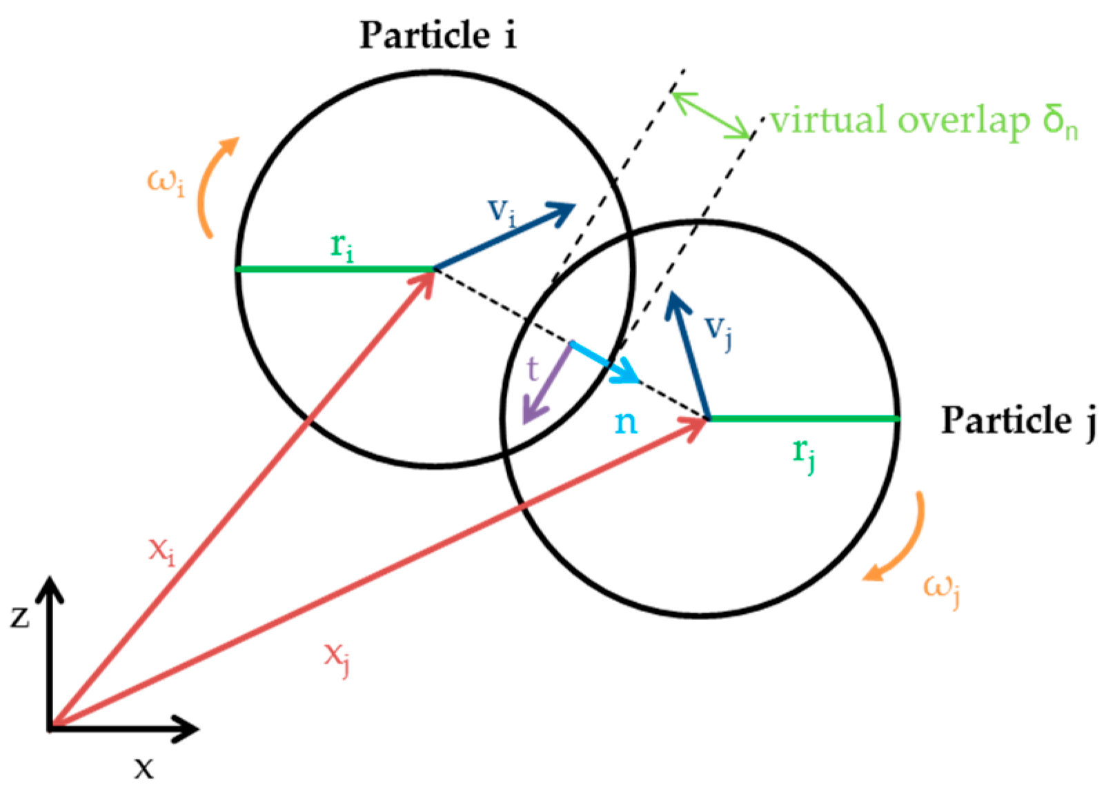
The algorithm used in DEM enables the determination of time-dependent movement and rotation of particles. It follows a sequence of single arithmetic operations, in which the first step consists in the identification of particle contact pairs. Due to the mentioned spring-damper system, the contact of two particles results in a “virtual overlap”. The ensuing forces caused by the overlap can be separated into tangential and normally-directed forces. Here, the tangential directed forces account for static and dynamic friction, whereas the normally-directed forces represent damping and recoil. Gravitational force is included in the model as well. By integrating Newton’s second law for the given system, the location and velocity for each individual particle can be determined at any given time step by:
A visualization of the acting forces and geometrical relations between two interacting particles is shown in
Figure 4:
Further details on DEM theory can be gathered from many different sources, such as [
2,
8,
9,
10].
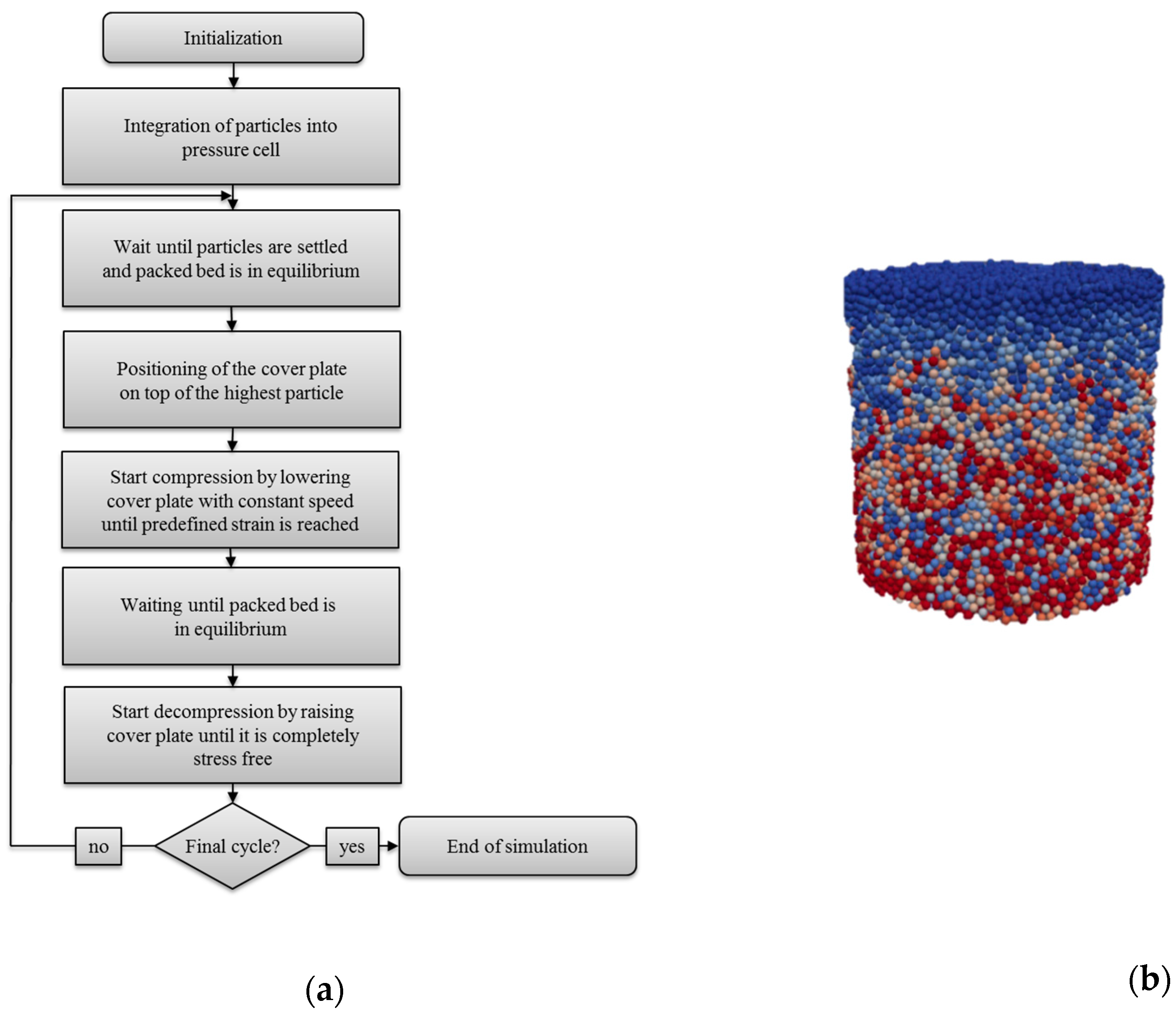
The 3D-UCT simulations presented in this paper were realized with the open source software LIGGGHTS. The implementation of the uniaxial compression test follows the sequence displayed in
Figure 5, which also shows an exemplarily visualization of a simulated packed bed.
4. Experimental Results
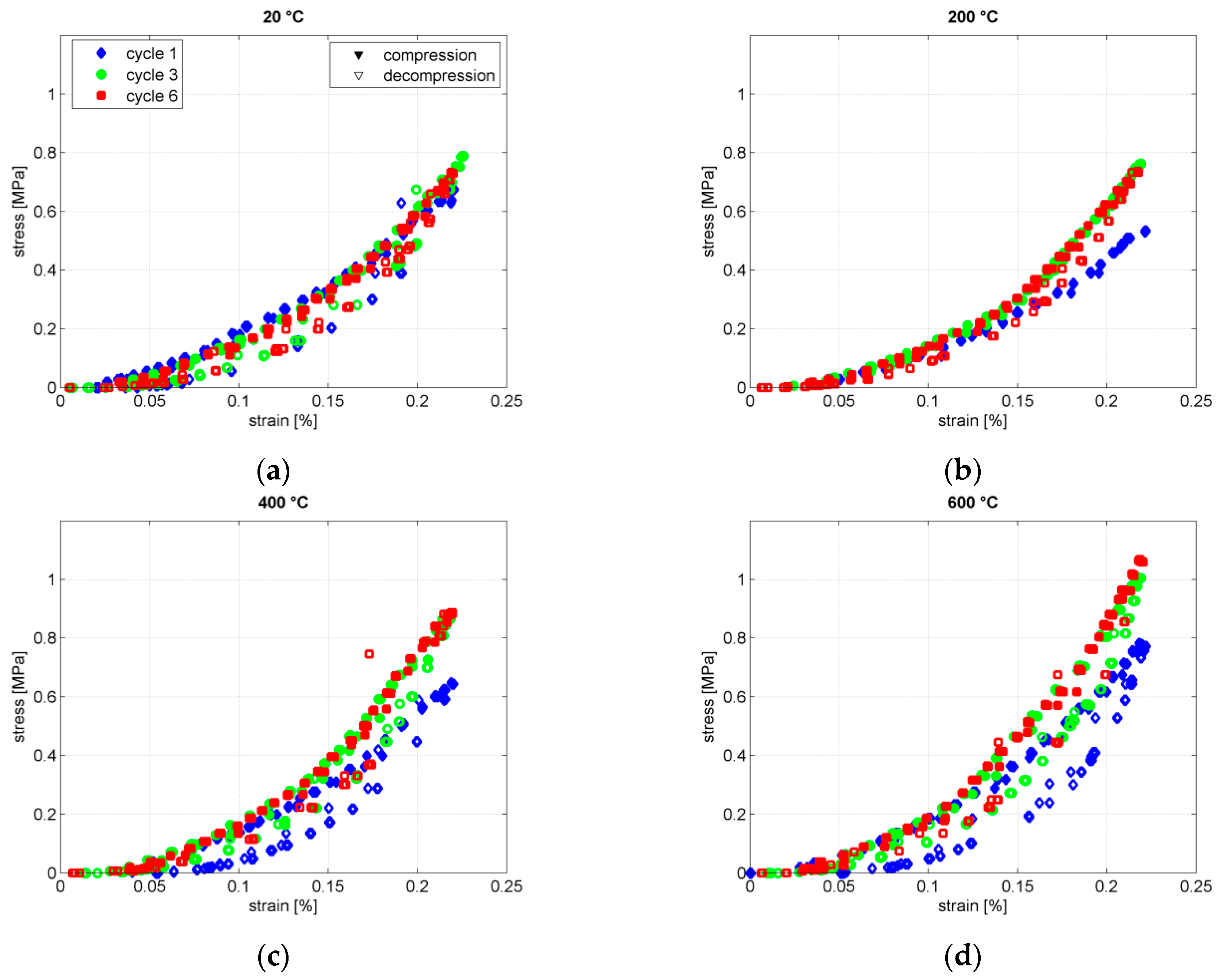
Uniaxial compression tests were carried out as described in the previous paragraphs. Compression-decompression cycles were repeated six times at four different temperatures (20 °C, 200 °C, 400 °C and 600 °C). The maximum amount of compression at each cycle was 1 mm of total packed bed height (which corresponds to about 0.2%–0.25% strain), since higher amounts of compression resulted in material failure of individual particles. The recorded stress/strain relations during compression and decompression of the packed bed at cycle one, three and six are displayed in
Figure 6.
The first observation to be made is the difference in compression and decompression stresses. The compression stresses at each cycle are consistently higher compared to the following decompression, which results in a hysteresis-like curve progression. This effect is explained due to energy dissipation processes in the form of inner friction and plastic deformation of the packed bed during the compression phase. There is also an obvious non-linearity in the stress-strain relation. Both of these effects are typical and well-observed phenomena of granular soil mechanics [
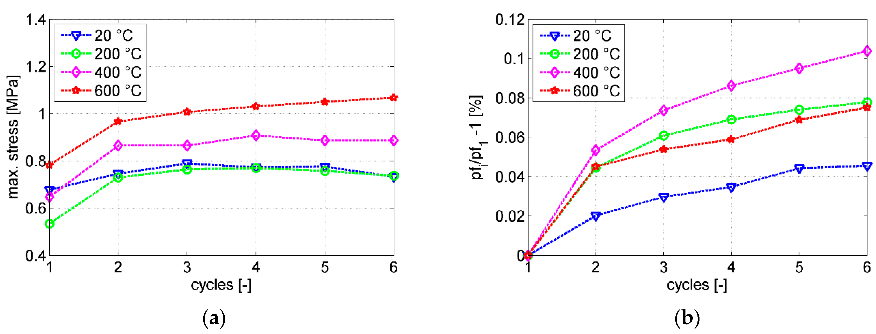
11]. The measured stresses tend to be lower for the first compression cycle, whereas the curve progression of the following cycles is nearly identical, but at a higher level than the first cycle. The reason for this is a less densely packed bed configuration of the pebbles at the initial state before the first compression. Irreversible particle displacements lead to denser configurations, which result in a significant increase in maximum stress, up to 40 % after the first cycle as displayed in
Figure 7a. For the measurements at 20 °C, this behavior is less pronounced, which means the particles were already densely packed before the first compression. This is a consequence of the manual filling process and general stochastical variance of particle configurations in a packed bed. Another observation is the increased stress during compression for higher temperatures. While this is less notable for the 200 °C data, the maximum exerted stress raises from 0.79 MPa at 20 °C to 0.9 MPa at 400 °C and 1.06 MPa at 600 °C. This increase is a result of the likewise increasing Young’s modulus of the ceramic material at elevated temperatures. Another result is the change of the packing factor during testing. Here, the packing factor (also called packing fraction or packing density) is defined as the rate of the accumulated solid volume of all pebbles in relation to the total packed bed volume, including the void volume. It is a measure of the densification level of the packed bed and thus is linked to its stress/strain response.
Figure 7b displays the change in packing factor after each cycle in relation to the packing factor after the initial first cycle. The initial packing factor is similar for all four packed bed configurations at around 59 %. There is only a minor increase in packing factor (between 0.02% and 0.1 %) for subsequent cycles, most notably after the first compression cycle. This means the initial configuration is already quite dense and close to the final configuration, which again, is a result of the manual filling process of the packed bed into the pressure cell. Another conclusion is that the exerted stresses from the packed bed are quite sensitive to the packing factor, since even small changes in packing factor result in significant changes of stress.
In the following paragraph, the results of the simulated UCT are presented and compared to the experimental data.
5. Simulation Results and Model Validation
The simulation model was set up to replicate the experimental procedure in terms of geometrical boundaries and material properties. For the implemented simulation sequence, refer to
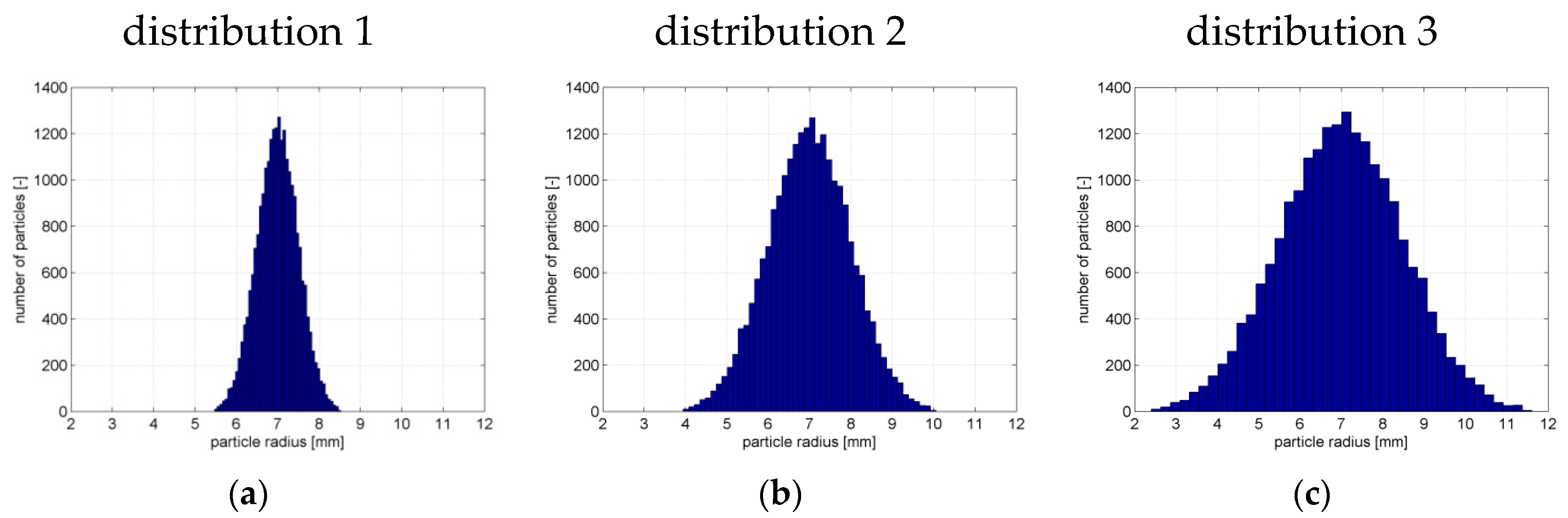
Figure 5. The initial configuration of the simulation model was significantly less dense then the experimental configuration at around 53 % to 54 % due to the different filling process of the particles into the simulation environment compared to the manual filling in the experimental procedure. In order to obtain a comparable packed bed configuration with similar packing factor, the simulated packed bed was compressed / decompressed for 100 cycles instead of only six cycles. The simulated particles for the reference case were 14 mm in diameter, the same as in the experiment. In addition to the reference case with a uniform particle distribution, three supplementary simulations were conducted with the size distributions visualized in
Figure 8. These simulations were carried out to gather insight about the influence of different particle size distributions regarding the resulting loads and to approximate the natural variances in size of the particles used in the experiment. It also highlights the advantage of the DEM model, since those straightforward simulations replace the otherwise required tedious experimental efforts.
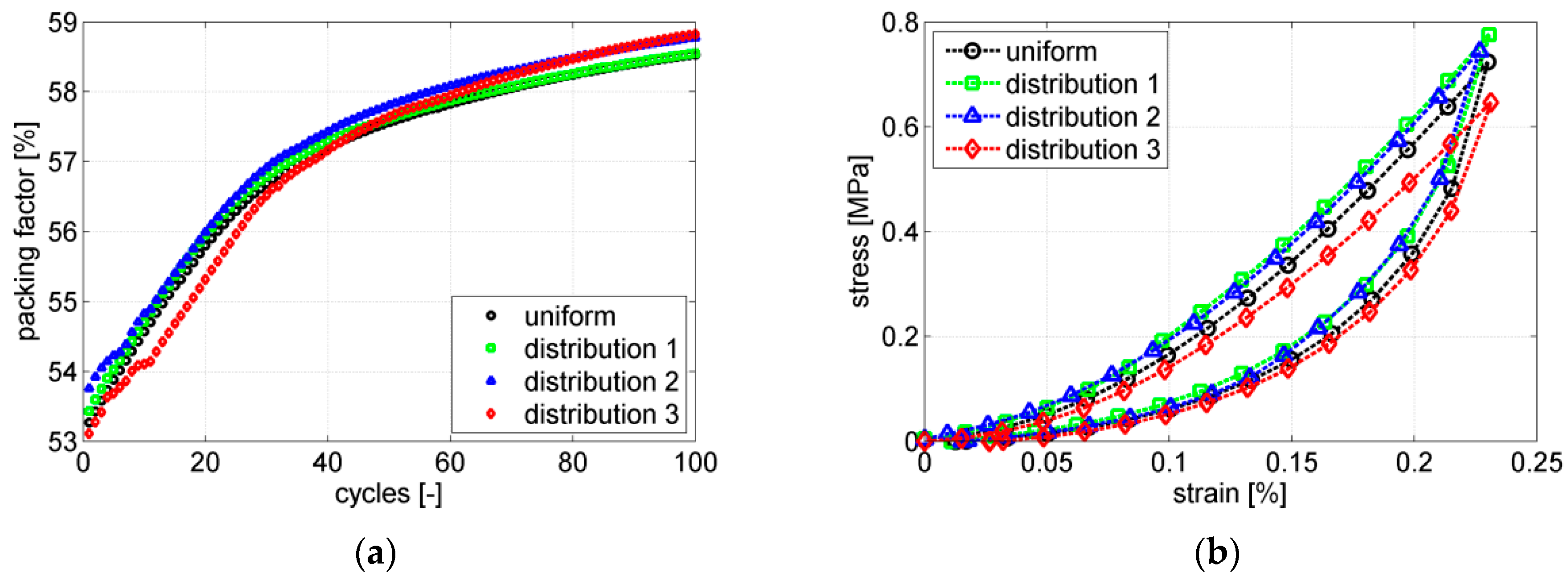
The results for the simulated packing factors at a temperature of 20 °C are displayed in
Figure 9a.
The packing factor increases drastically for early cycles, which mean the initial packed bed configuration is much looser then in the experimental run, where the increase in packing factor over multiple cycles is negligible (see
Figure 7). Polydisperse distributions of particle sizes lead to a slightly denser packed bed configuration. The increase in packing factor slows down significantly with an increasing number of compression cycles, indicating the approach of a maximum dense packed bed configuration. The uniform particle size distribution and the distributions 1 and 2 show a parallel curve progression, whereas the slope of distribution 3 is slightly steeper. The reason for this is the broad particle size distribution, which takes more cycles to reach a maximum dense configuration of the packed bed. The stress-strain results for the final cycle are shown in
Figure 9b. Only minor differences are observable between the different particle size distributions. While the maximum stresses of distribution 1 and distribution 2 are almost identical with the maximum stress of the uniform particle size distribution, distribution 3 is about 0.1 MPa lower. Again, the reason for this is the looser packed bed configuration of distribution 3 due to broader distribution.
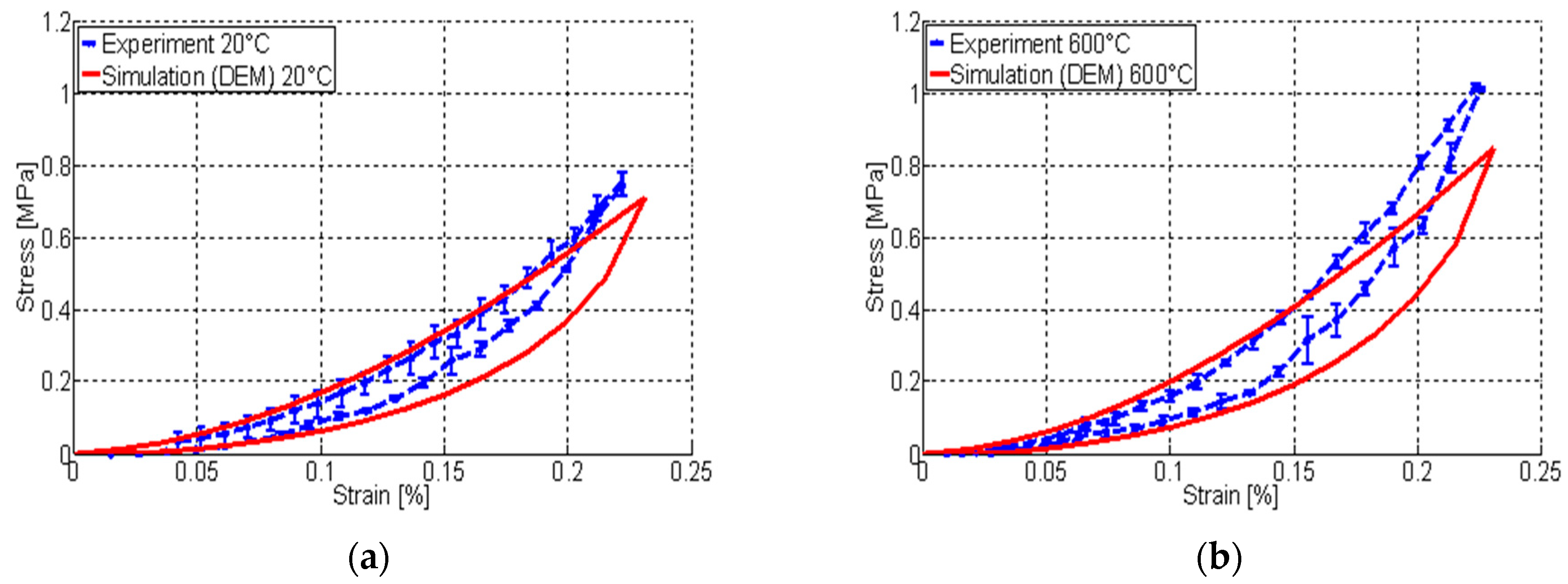
Since the overall insignificant influence of the particle size distribution, simulations at elevated packed bed temperature levels were conducted only for the uniform particle distribution. In
Figure 10, the simulated stress-strain relations for 20 °C and 600 °C particle temperature and a uniform particle size distribution are compared to the obtained experimental data. Here, the error bars of the experimental result represent the standard deviation of the mean values of four conducted experimental runs. For the simulation results, the error bars are not shown due to low stochastical differences between them.
The simulated results conform quite well to the experimental data, both in quality and quantity, although the simulation curve appears to be smoother overall, and stresses at higher strains slightly fall off compared to the experimental results. Those differences are the direct consequence of simplified modelling assumptions, such as perfect sphericity and smoothness of the particles. Furthermore, the packed bed configuration for the modeled packed bed is still slightly less dense than the experimental configuration, despite simulating 100 compression cycles. However, for the sole purpose of model validation, these marginal differences of the packed bed configuration are acceptable. In addition, minor deviations are expected due to the small variances in particle size distribution of the particles used in the experiment.
Overall, there is a good agreement of the DEM simulation results compared to the experimental results, proving the DEM model to be fit to reproduce packed bed behavior under uniaxial compression.
6. Outlook
The resulting stress-strain relations of the specific packed beds can be utilized in future works for the parametrization of computing time-efficient continuum models. This implementation escapes the scope of the study at hand, therefore, only a brief overview of the subsequent procedure is outlined in this paragraph.
Based on the stress/strain relation of the selected packed bed presented in this study, an effective Young’s modulus of the packed bed can be determined. The effective Young’s modulus is a key parameter for describing the packed bed as a continuous medium instead of just as a bulk material. It is a non-linear packed bed property dependent on the packed bed’s stress state and its temperature. Based on the gathered data, the effective Young’s modulus is calculated as the stress to strain ratio of the packed bed for every simulated packed bed configuration, e.g., at various temperature levels or at different packing factors. Reimann’s [
7] approach describes the effective Young’s modulus as a function of temperature and stress state of the packed bed with only a few packed bed-dependent material parameters. These parameters can be fitted for each packed bed configuration to approximate the gathered data from the uniaxial compression tests. The effective Young’s modulus parameterized in this way may be used as input for describing the material behavior of the packed bed in an appropriate finite element model. Thus, it is possible to simulate the mechanical behavior of the packed bed with consideration of the changing temperatures and packed bed configurations, as they are expected during operation of a large-scale thermal energy storage system.
7. Conclusions
Packed beds represent a suitable option as heat storage material for thermal energy storage due to cost reduction potential and high thermal performance compared to conventional storage inventory. For large scale applications, knowledge of the packed bed behavior during thermal cycling is crucial in order to accurately calculate the thermo-mechanical loads and properly design the storage. Uniaxial compression tests provide meaningful insight of the packed bed’s behavior under external load. In the frame of the work at hand, appropriate simulation models have been implemented using the discrete element method to simulate uniaxial compressions of the packed bed. In order to validate this model, a specifically designed test rig was built up and is introduced in this paper. The simulation model was successfully validated by comparing stress-strain correlations of simulation and experimental results of uniaxial compression at different temperatures up to 600 °C. Additionally, the influence of packed bed temperature and packing factor on the packed bed stress during uniaxial compression was investigated by assessing the experimental and simulation data. The presented and validated methodology facilitates the conduction of uniaxial compression tests via discrete element model instead of tedious experimental effort. Especially, since there are a lot of viable and possible packed bed choices (e.g., different materials, particle sizes and particle shapes) depending on the specific TES application, the possibility to use an easy to adapt particle discrete model may be proven to be significantly faster and more convenient then carrying out experimental studies for each case. Further experimental effort for the parametrization of continuum models may also be reduced or entirely replaced by other suitable discrete particle models.


