1. Introduction
Reflex reflectors, usually composed of cube-corner arrays [
1], can reflect light back along vectors that are nearly parallel but with a direction opposite to the incident light [
2,
3]. Reflex reflectors attached on cars or clothing can increase visibility in the dark for safety [
4] and have been applied extensively in vehicle applications [
5]. For instance, regular reflex reflectors [
6,
7,
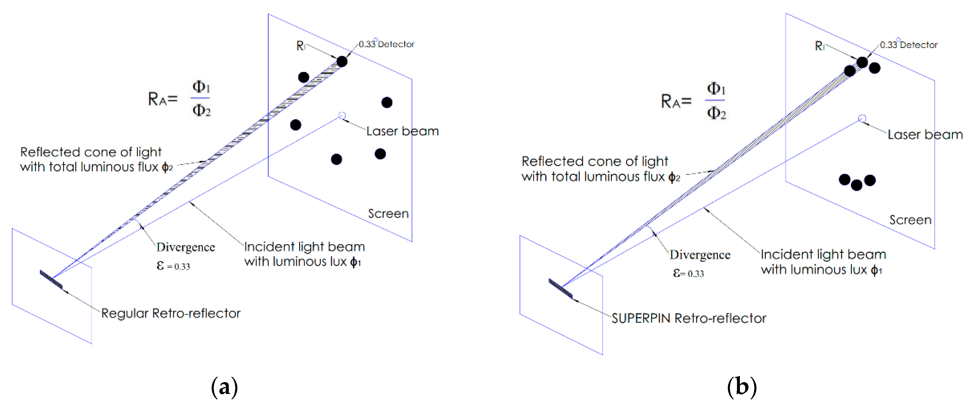
8], as shown in
Figure 1a, can diverge the reflected energy into multiple light beams with equal emitting angle intervals [
9]. It is also the most commonly used retro-reflecting device for vehicles currently [
7,
10]. In contrast to regular reflectors, the SuperPin reflex reflector not only reflects light beams but also concentrates them to amplify the light intensity of signals for observers, as shown in
Figure 1b [
11]. Owing to the highly effective retro-reflection ability, SuperPin retro-reflectors have been replacing regular retroreflectors in vehicle application markets [
5,
12].
According to regulations of the ECE (Economic Commission for Europe), vehicle signage needs to return light back to an observer located at 0.33 degrees above the light source [
13], and the coefficient of luminous intensity
RI should be greater than threshold values within 20° angle of light incidence [
5,
14]. The vehicle signage performance
RI is evaluated by the ratio of the strength of the reflected light (retro-reflected light intensity) to the amount of light that falls on the retro-reflector (incident light illuminance), as shown in
Figure 1.
RA is the measure of retro-reflection efficiency, defined as the ratio of the flux of incident light to the total flux of the reflected cone [
12,
15]. Consequently, vehicle signage would be observed to be brighter as its
RI value increases [
13,
16].
It is usual for reflex reflectors to have a curved shape; for example, to fit the corner of a vehicle [
1,
2,
3,
4,
5,
17]. Cube-corner structures are, thus, distorted to complete the curve, so that their effective working area and reflection efficiency are affected, thus leading to the retro-reflector being against EU ECE regulations [
5,
11,
17].
In this paper, a curved reflex reflector with a new cube-corner structure is proposed and demonstrated. By using genetic algorithms for optimization, the angles and the positions of the pins, which serve as the building elements of corner-cube reflectors, play a role as the parameters to enhance the performance of a curved reflex reflector. Compared with conventional retro-reflectors, it is found that a 46% higher retro-reflection efficiency and 33% larger working area can be accomplished with our optimized design.
2. Principles
The EU ECE standard is designed to reduce injuries and deaths resulting from traffic accidents by providing adequate illumination of the roadway and by enhancing the conspicuity of motor vehicles on public roads so that their presence is perceived, in daylight, darkness and other conditions of reduced visibility. A white reflex reflector provides an observation angle of 0.33° (EU ECE regulations), not less than 1680 millicandela/lux at a light entrance angle of 0°, not less than 1120 millicandela/lux of light at 1° up and 10° down and not less than 560 millicandela/lux including the entrance angle at 20° left and 20° right. [
5].
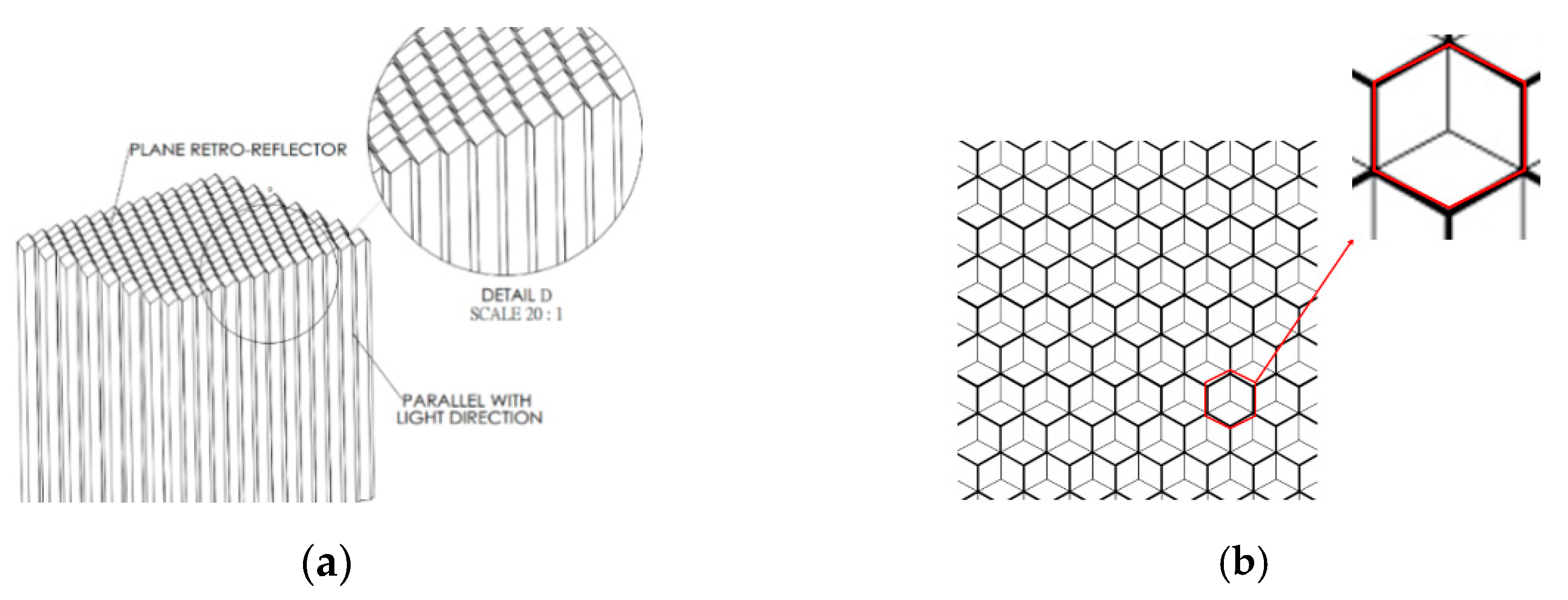
The corner-cube retro-reflector (CCR) is based on groups of three perpendicular planes, as shown in
Figure 2. Conventionally, the dihedral angle between any pair of reflecting faces is made to be almost exactly 90° [
1], so that the reflected beam is exactly antiparallel to the incident beam [
13]. If the angles differ from 90° by an amount, the reflected beam will be converged or diverged in multiple beams to achieve the required application [
1].
Through an array of pins, corner-cube retro-reflectors can be produced as shown in
Figure 2. The orientation of each face is given by the normal unit
,
, and
for each face. The reflection from each face reverses the component of the light’s velocity vector that is normal to the face. Let
and
be the directions of a ray before and after reflection, respectively, with the vector V′ given by
=
− 2(
·
)
, where
is normal to the face. Applying the above formula three times yields the direction of the reflected beam for a particular order of reflection. Formulas for the direction of the reflected rays after the three reflections are given by Chandler’s formula:
where
is the final direction;
is the original direction: α, β, γ are the small angles by which the angles between the three mirrors exceed right angles and
,
, and
are normal to the three mirrors taken in order in a right-hand sense. Equation (1) is valid at the first-order when the mirrors are nearly mutually perpendicular. The angle α is the angle between the faces whose normals are
, and
. The normals may be strictly perpendicular; that is, they do not need to include the small deviations caused by the dihedral-angle offsets. The directions of the reflected rays were computed by applying the law of reflection three times.
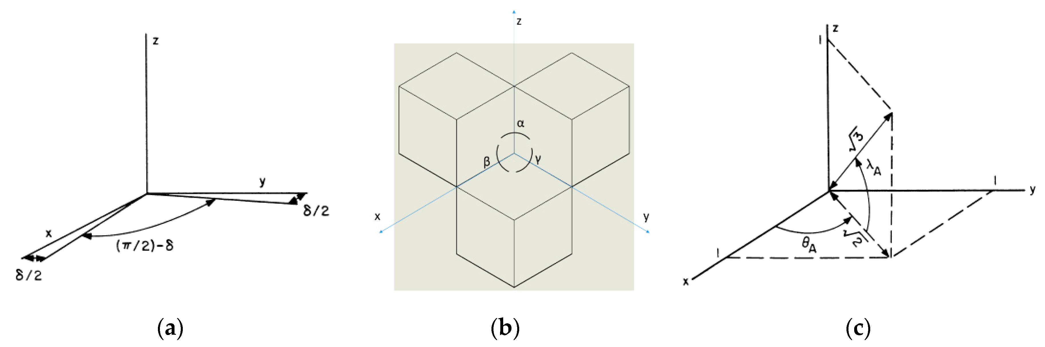
The unit normals to the faces can be computed as follows and as shown in
Figure 3. Let the normals to the faces without dihedral-angle offsets be the unit vectors
,
, and
along the three coordinates x, y, and z, respectively. If the angle between the zx plane and the zy plane is α = (π/2) + δ
1, the xz plane and the xy plane is β = (π/2) + δ
2, the yz plane and the yx plane is γ = (π/2)+ δ
3, shown in
Figure 3b; this can be expressed by Equations (2)–(4),
For small angles δ, the above expressions are quite adequate. Offsets in the other two dihedral angles can be similarly represented.
It is desirable to have the unit normals given in the coordinate system of the symmetry axis of the corner cube since the incidence angle of the laser beam is given with respect to this axis. The symmetry axis is in the direction of the vector x = y = z = 1, as shown in
Figure 3c; we see that
=
;
=
;
=
;
=
. The normals in the xyz coordinate system can be given in the coordinate system of the symmetry axis by rotating the original coordinate system about the z axis by θ
A and about the y axis by −λ
A. This brings the x axis along the axis of the matrix form, and the total rotation is given by:
Substituting the values of the sines and cosines and multiplying the matrices, we obtain
=
;
=
;
=
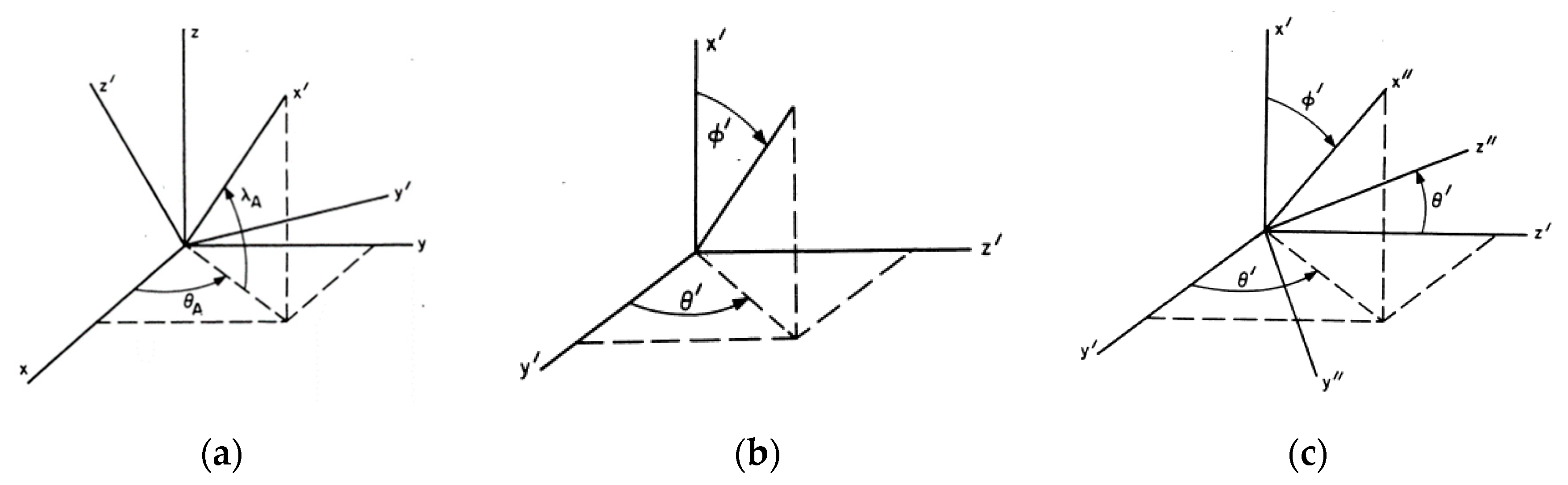
. In
Figure 4a, the unprimed axes represent the original coordinate system and the primed axes are the rotated coordinates.
The incident beam after reflection at the front face is in a direction given by the angles θ′ and ϕ′ in the primed coordinate system, as shown in
Figure 4b.
A second rotation of the coordinate system must be performed to get the normals to the faces in the coordinate system of the laser beam. By rotating the coordinate system about the x′ axis by θ′ and then about the new z′ axis by ϕ′, we obtain:
The relationship of the primed and double-primed coordinate axes is given in
Figure 4c. The x′ axis is the symmetry axis of the reflector, the y′, z′ plane is parallel to the front face, and the x″ axis is parallel to the beam after it enters the corner cube. In this study, we used a hollow corner cube; the reflections can be done for all six possible sequences of reflections by taking the incident beam, given by the vectors x″ = –1, y″ = z″ = 0, and reflecting it from each of the normals to the faces in the double-primed coordinate system. The y″ and z″ coordinates of the reflected beam give the deviations from the incident direction.
The beam spread at normal incidence when all dihedral angles are offset by the same amount is given by the formula ε
1 =
n δ
1, ε
2 =
n δ
2, ε
3 =
n δ
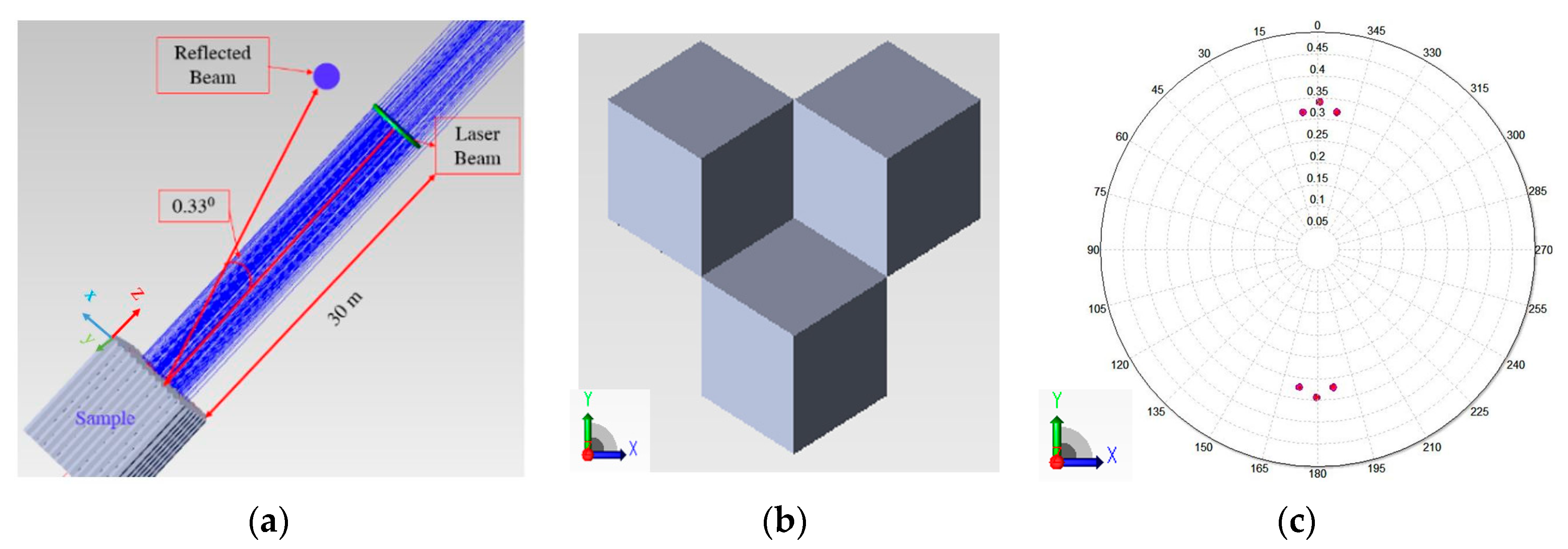
3, where δ is the angle by which the dihedral angles exceed 90° and ε is the angle between the incident and the reflected rays. When the light passes through CCRs, there will be a change in the direction of reflection. The direction of the incident beam is determined by θ′ and ϕ′ in the primed coordinate system. Based on the above mathematical theory, the optical simulations through the TracePro software (Lambda Research Corporation of Littleton, Massachusetts, USA) show that CCRs with the same dihedral angle can reflect six beams with the same reflection angle ε with respect to the incident beam. When the dihedral angle is δ
1 = 0.095°; (α = 90.095°); δ
2 = 0.095°; (β = 90.095°); δ
3 = 0.12° (γ = 90.12°), the reflected beams can be found that ε
1= 0.33°, ε
2 = ε
3 = 0.31°, which fit EU ECE regulation requirements. The simulation result is shown in
Figure 5c.
By using the different angles between each pair of facets, we can move the three retro-reflected rays on the top into one direction and the other three into another direction, as shown in
Figure 5c. In this way, we dramatically improve the optical performance of a corner cube, because the retro-reflected energy in a given direction is tripled. We call this techique SuperPin technology. The experiment beam pattern retro-reflected from the SuperPin corner is shown in next section.
3. Experimental Setups and Analysis
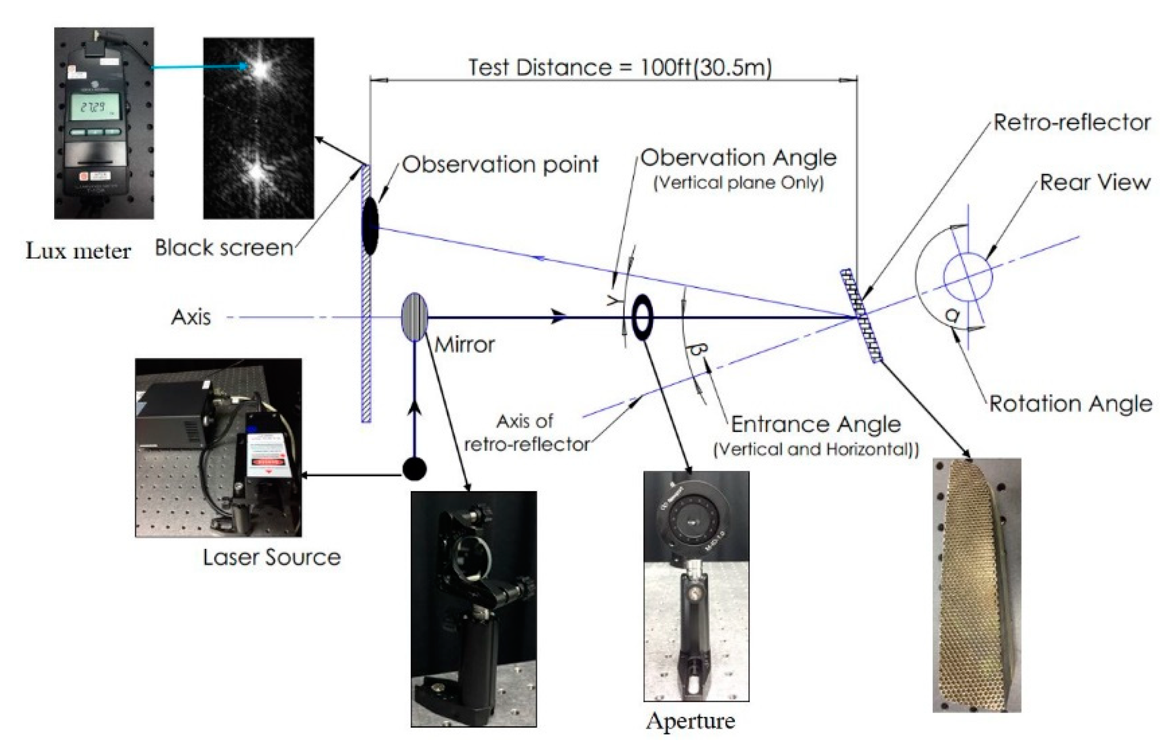
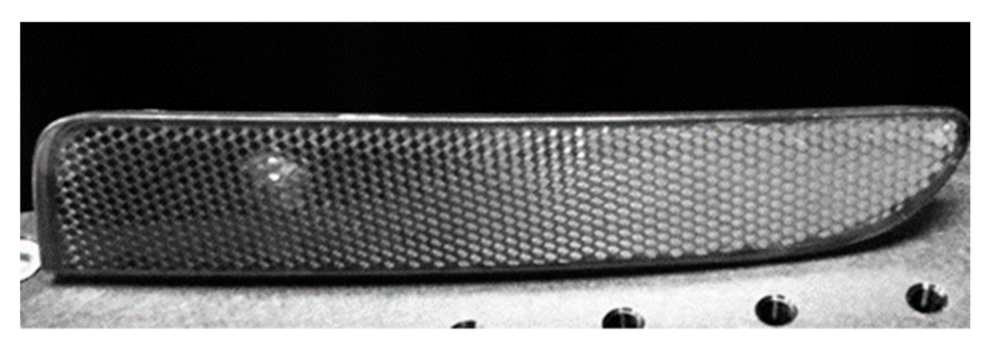
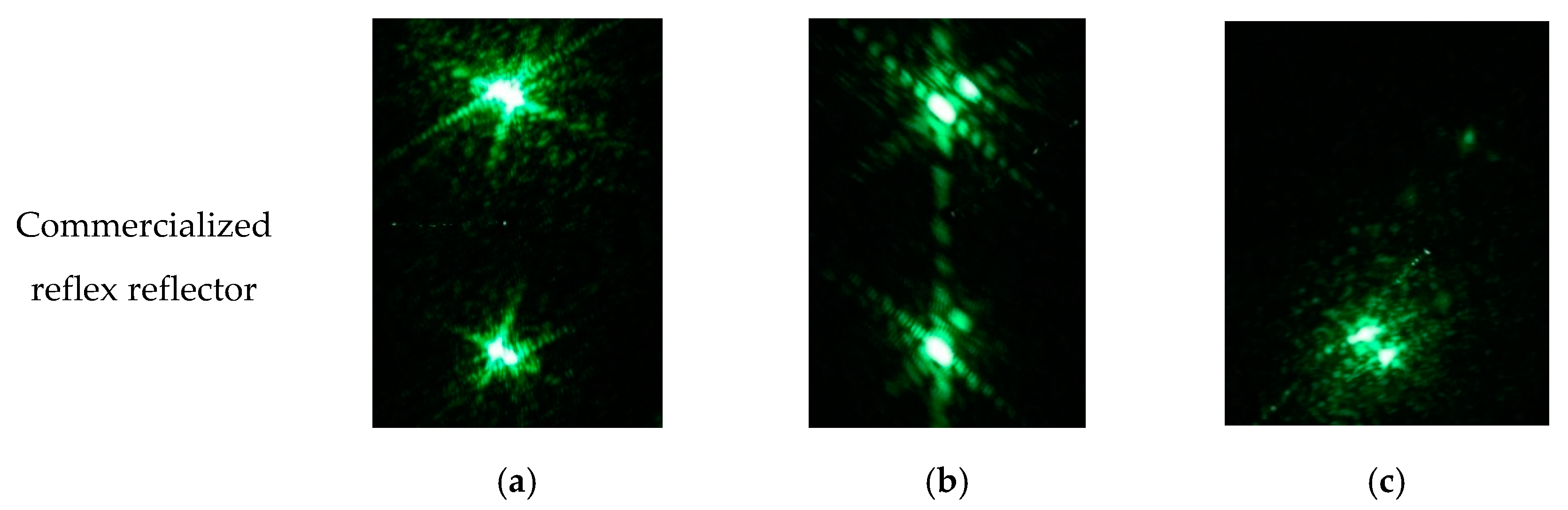
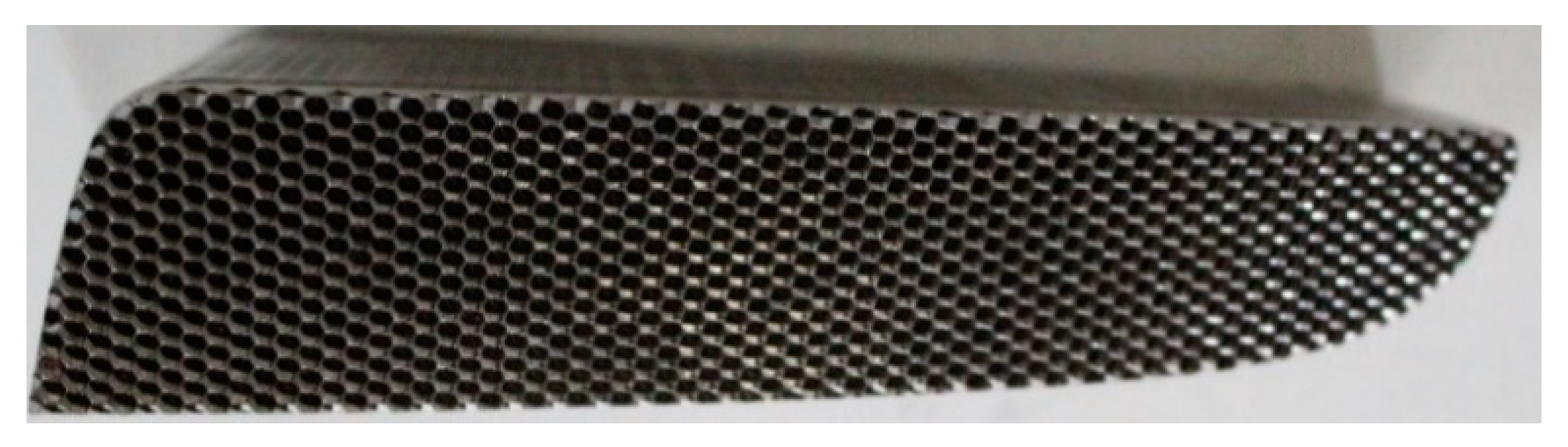
In order to investigate the property of a curved reflex reflector, a commercialized CCCR (curved corner cube retroreflector) for a car was used for testing, as shown in
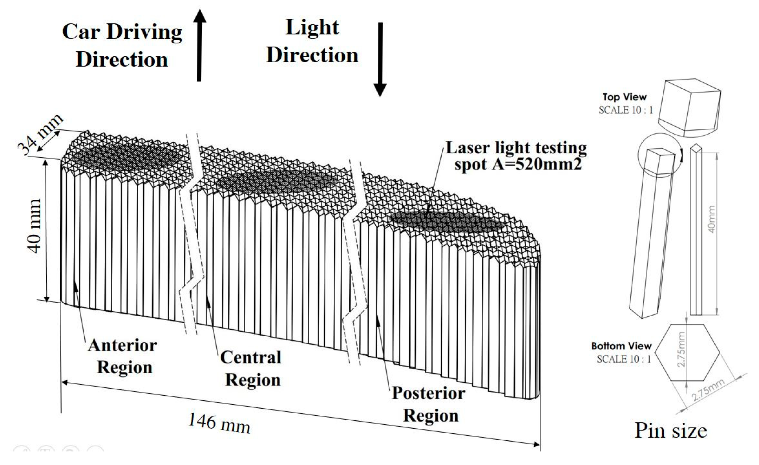
Figure 6. The 146 × 34 mm sample is made of PMMA (poly methyl methacrylate) and composed of 2.75-mm sized corner-cube arrays. The product is provided by OWL LIGHT AUTOMOTIVE MFG. CORP (Lukang, Chunghua, Taiwan) and it has been in mass production for automotives in the EU. The experimental setup for CCCR testing is shown in
Figure 7. In the optical setup, a 532 nm diode-pumped solid state (DPSS) laser operated with a 5 mW output acted as the light source. The distance between the laser and the curved reflex reflector was set to be 30.5 meters to measure the reflected light spot. Based on the laser spectrum specification, its coherence length is calculated to be about 0.5 mm, which is less than the corner-cube dimension of 2.75 mm in the experiments. Therefore, the retro-reflected output spots were spatially incoherent, and the laser can be considered as an incoherent light source for the following retro-reflector testing experiments. The laser light had an incident angle of 0° with respect to the car driving direction, as it shone on the commercialized CCCR with a spot area of 520 mm
2. As a result, several retro-reflected light spots can be found on the black screen located 30.5 meters away from the test sample. A Minolta T10 illuminance meter was used to measure the illuminance of the sample and of the retro-reflected light spot in order to get the incident light illuminance (in lux) and the retro-reflected light intensity (in candela). The coefficient of luminous intensity
RI and retro-reflection efficiency
RA of the test sample can be obtained. During experiments, the anterior, central and posterior regions of the CCCR were investigated. Their locations and the car’s driving direction are presented in
Figure 8.
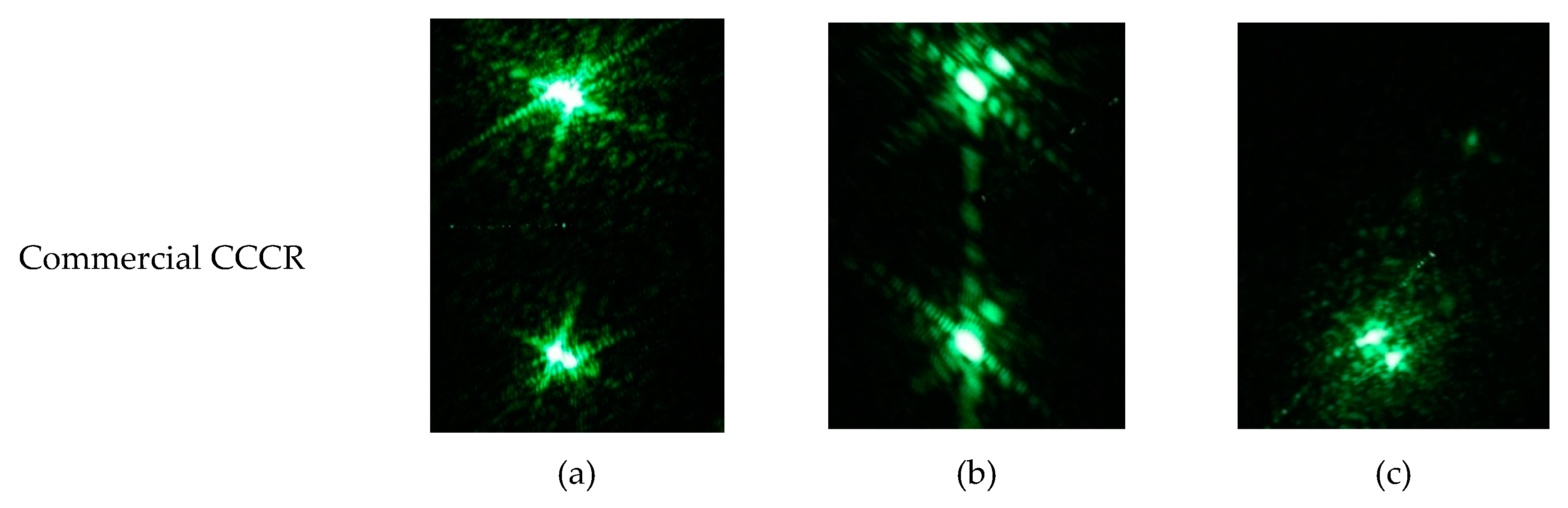
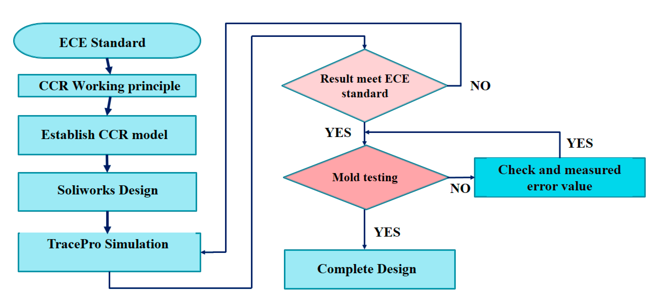
Initially, the laser light was adjusted to be parallel with the driving direction and focus on the central part of each region. The reflected outputs are shown in
Figure 9a–c, respectively. It can be found that the reflected light spots become gloomy as the test region shifted from the front part to the end part of the CCCR. The curved shape of the CCCR seems to have caused interferences regarding its functions.
In order to enhance the performance of the.SuperPin CCCR, a single beam parallel with driving direction was used to probe the reflecting surfaces of the posterior region by optical simulations. As shown in
Figure 9, the anterior and the central regions areas have a higher performance than the rest. In contrast, at the upper position (0.33°) of the posterior area of CCCR, there is almost no reflected light. Therefore, it can be concluded that the posterior area cannot meet ECE regulation requirements.
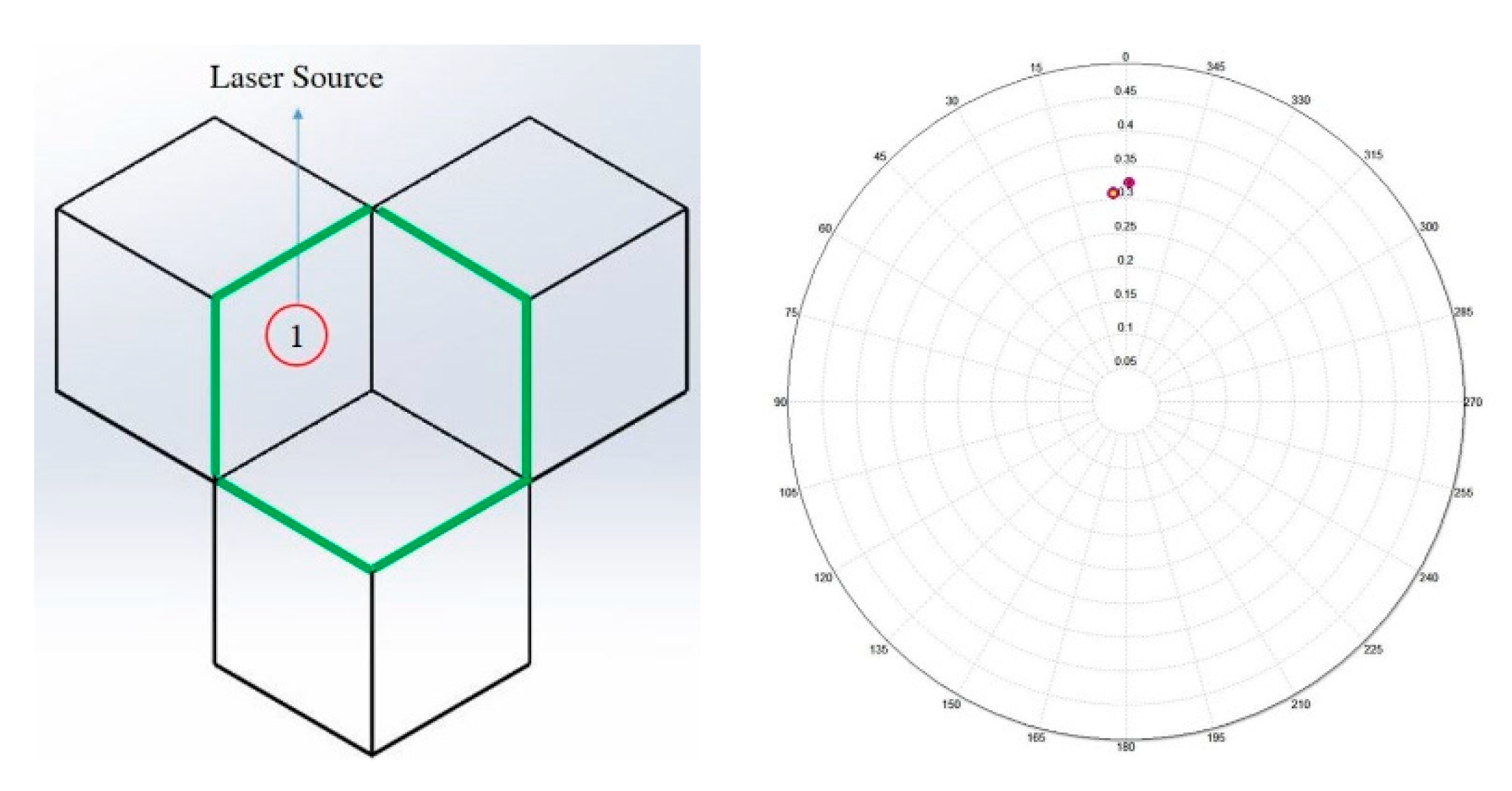
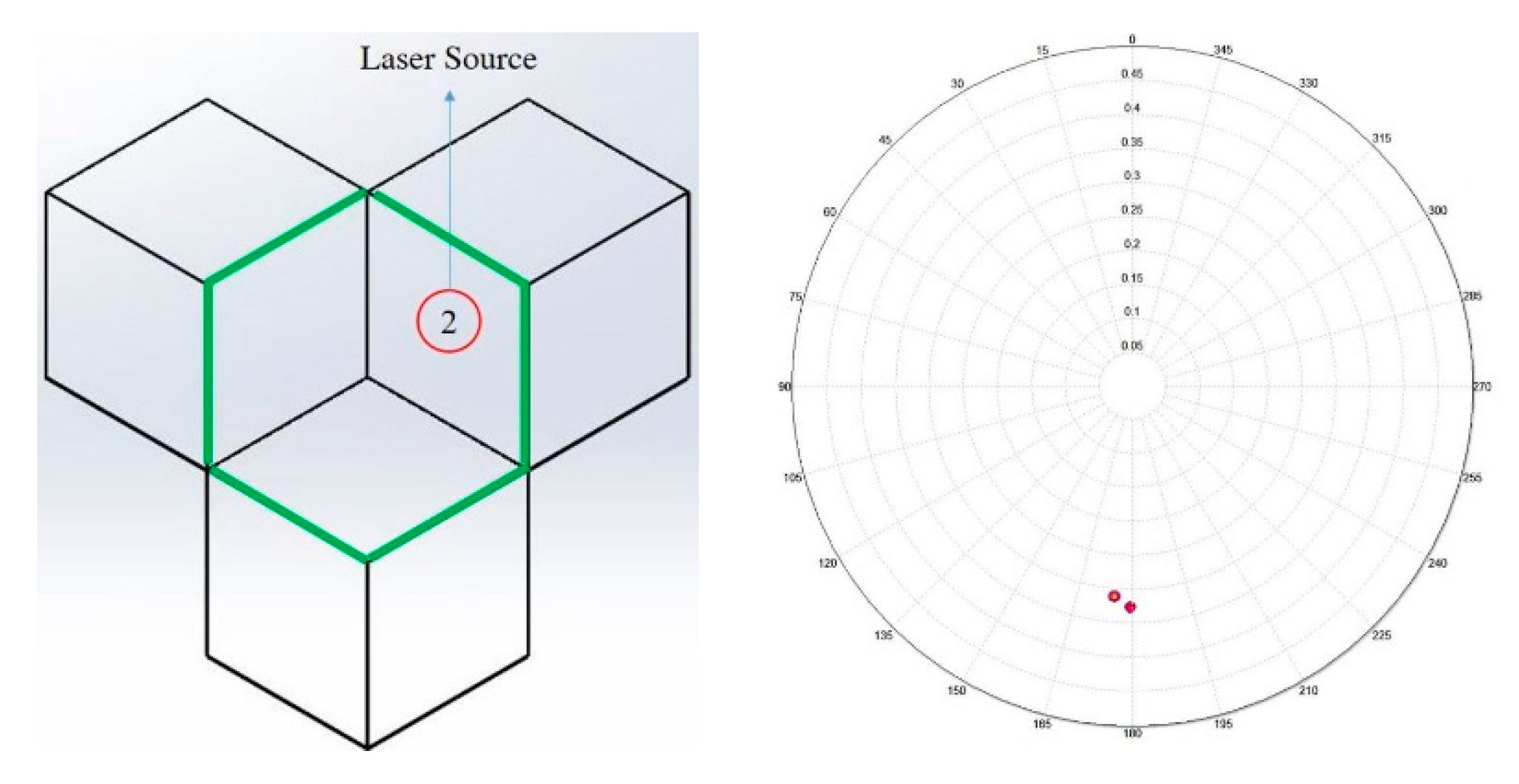
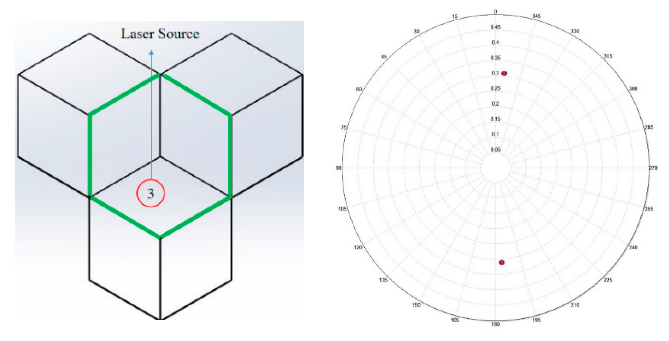
In order to rescue the posterior region, the relationship between the incident light location of CCR and its retro-reflected light direction is investigated. The simulation experiments of rays shining on face #1, face #2, and face #3 are conducted, respectively. Their resulted reflected light intensity distribution are shown in
Figure 10,
Figure 11 and
Figure 12. Comparing
Figure 9 with
Figure 10,
Figure 11 and
Figure 12, it can be understood that the #1 and #3 reflecting surfaces in the posterior region do not function normally, so that three light spots are missed in the output screen. If the pin group structures could be reconstructed, the coefficient of luminous intensity R
I and the reflection efficiency R
A would be improved.
4. Optics Design and Verification
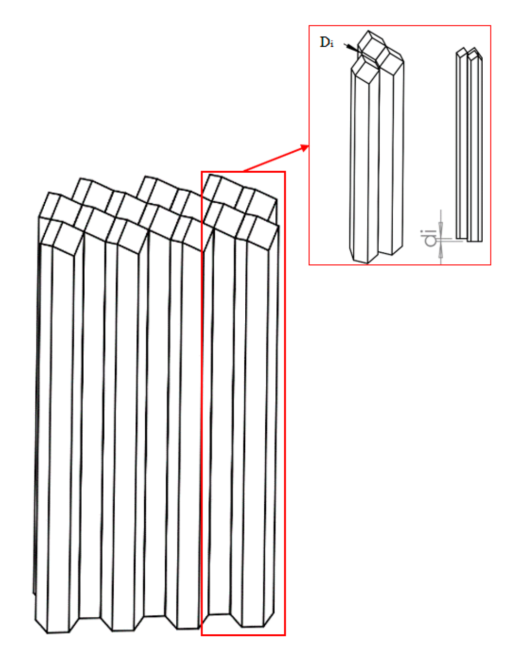
In order to remedy the ineffective posterior working area of the commercial design, two groups of pins were connected together as the double pins group to compose the CCCR, as shown in
Figure 13. Fifteen pieces of double-pin groups were arranged in parallel to the car driving direction to compose the primary CCCR; one pin group touches the curve reference surface and the other one is free to translate in the car driving direction. The height difference between the neighboring pins in a group of double pins and the double pin group are named d
i and D
i, respectively.
The object function f defined by the Equation (7) was determined in the optimization process. The optimization process encompassed three fragments.
Object function: The equation that describes the value of the object function of the optimization program established by genetic algorithms is as follows:
where
wi is the weight parameter of the object function,
mj is the value of the measured target, which is determined by the intensity sensor through each optimal loop when running the program, and
tj is the optimization target defined with a value corresponding to the retroreflective light intensity on the retroreflector plane.
Luminous intensity function: In order to improve the primary CCCR further, the add-on ray tracing simulation tool OptisWork (Optis SAS, La Farlede, France), embedded in SolidWorks mechanical design software, was used to search suitable variable parameters to get an optimized CCCR, using d
i to elevate its performance and D
i to fit the reference curve for the outlook of CCCR smoothly. The constraint of each variable parameter is determined by the curvature of the CCCR surface. The lighting performances, such as intensity distributions, illumination uniformity and optical efficiencies of CCCR, can be accomplished to meet targets by using optimization. In the study, the luminous intensity function serves as the object function, and the value R
I at the upper 0.33° is targeted to be maximum in the solution searching process. We search for an approximation of the luminous intensity (R
I) I(φ,a,b,c) as object function, which is at the polar angle Φ in the form:
where K is the number of functions to sum and x
k, y
k, z
k are the function coefficients that we expect. For brevity, coefficients are written as vectors x = (x
1, x
2,...,x
k), y = (y
1,y
2,...,y
k), z= (z
1,z
2,...,z
k). The interval range of the coefficients is: a = [0,0.81], b = [−1,1], c = [0,100]. Discrete optimization algorithms will work on the finite subsets where the possible values will be: x* ϵ {0, 0.001,0.002,...0.81}, y* ϵ {1, 0.9,0.8,0.7, ..., −1}, z* ϵ{0, 1, 2, ...,100}.
The components in the OptisWork optimization software have been configured to incorporate three elements: the light source, intensity sensor and CCCR. The interspace between the CCCR and the surface source had been fixed as stated by ECE standards as the interval of the intensity sensor. For the rapid finishing of the optimization, D
i is initially set to be constant and each double-pin group was assigned a value of
di as a variable. Based on the lengthwise extent and bend of the curved surface, dual pins had 15 groups that comprised 15 variables of
di (from
d1 to
d15). This is illustrated in
Figure 13. The constraints of each variable of
di are determined by the curvature of the contact surface. Each variable has a non-identical limitation of height values and is contingent on the situation of the surface that merit should fluctuate from 0.01–0.81 mm. The territory of a CCCR which has extreme curvature will have the highest altitude value. Our optimal goal should focus on the posterior area, where the lowest reflectivity is achieved, and improve the reflectivity of light. As shown in
Figure 8, the restriction was determined by the location of each region.
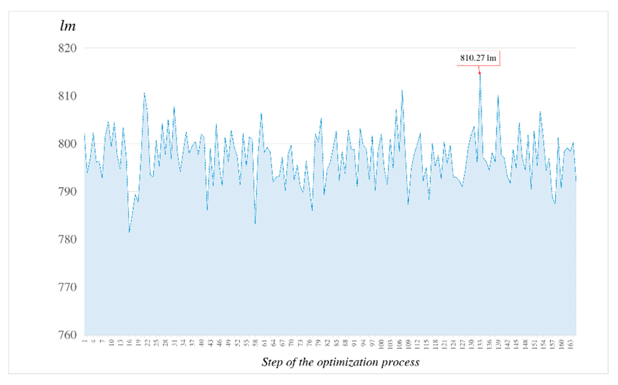
In order to set the target value of the optimization, the simulation experiment with a flat regulated CCR was exercised to find the reflected light power as the reference by a 1000 lumen incident beam. The resulting power was 850 lm and was used as the target for the subsequent searching of the optimized CCCR. By running the scheme in optimization steps, manually limited to 500 searching steps to quickly find a better solution, the best results were determined in step 139, as shown in
Figure 14. The final intensity sensor value was shown to be 810.27 lm, which was also the output power reflected by the optimized CCCR.
In the initial optimization process, the mathematical equation for the intensity distribution of reflected light entered into the program is expressed in the measurement value of the intensity sensor. The luminous intensity
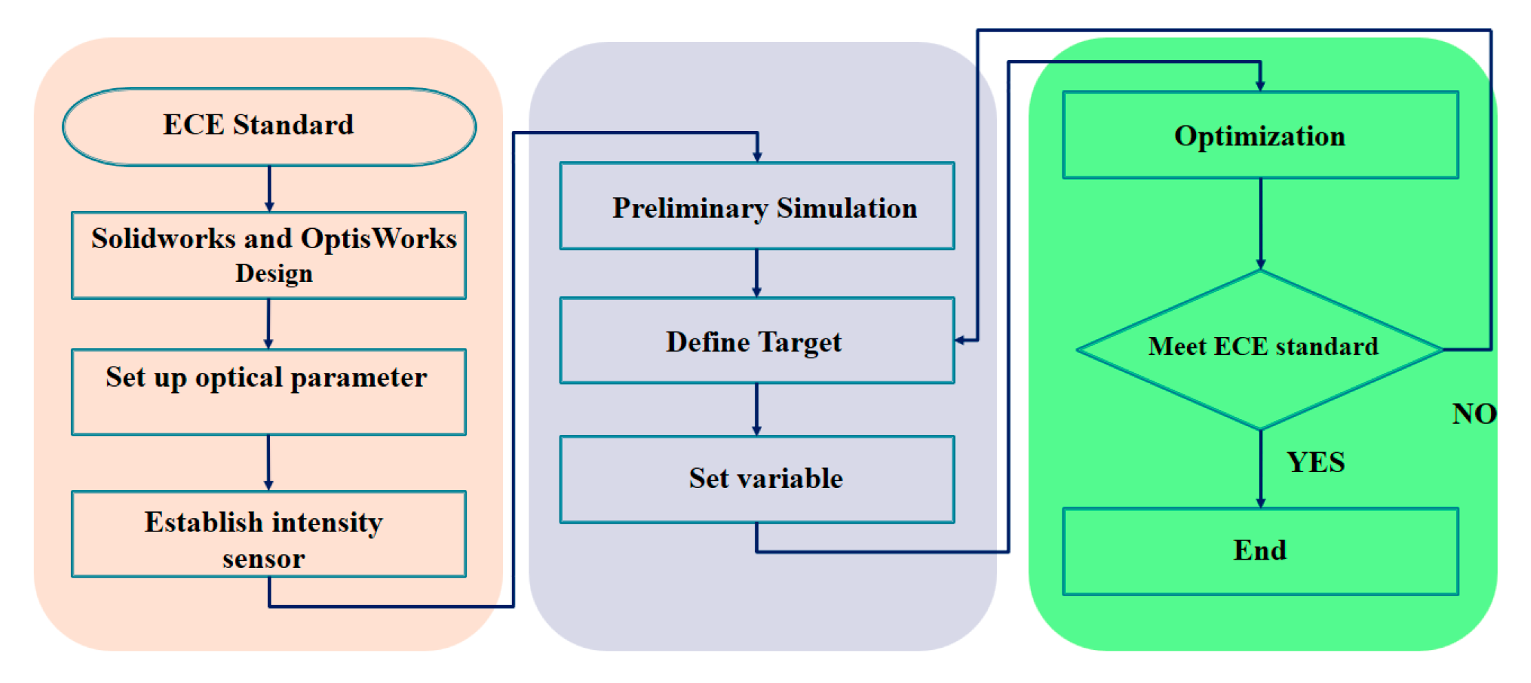
RI is defined by I(φ, a, b, c) at the polar angle of φ, shown in Equation (8). The target of the optimization process was defined as a value corresponding to the retroreflective light intensity on the retro-reflector plane. During the optimization, to have the CCCR meet the requirement of the ECE standard at 0.33° and maximum reflection efficiency, the values of δ and d
i were found through the workflows shown in
Figure 15 and
Figure 16, respectively.
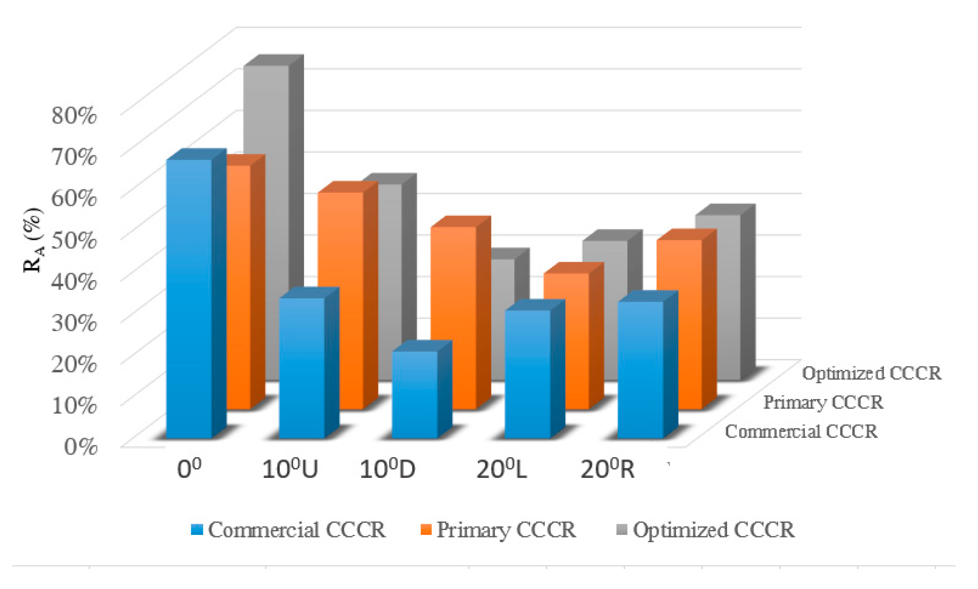
As the optimization is terminated by the program, the optimized CCCR with the same curve as the commercial one was obtained. After the optimization process, the optimized CCCR was analyzed for comparison with the commercial reflector by simulations. The distance from the light source to the CCCR is set as 30.5 meters and the diameter of laser beam is 25 mm. The CCCR is kept with its car driving direction at 0°, 10° (up, down) vertically, and 20° (left, right) horizontally with the incident light, respectively, to perform the optical tests of ECE regulations. The resulting intensity distributions by 0° incident light to the anterior, central and posterior regions sequentially are shown in
Figure 17. The results showed that the optimized CCCR can contribute much greater effective light intensity than that of the commercial design (no effective retro-reflection at 0.33° up), as shown in
Figure 17c,f. The candela values shown in
Figure 17 showed that the light reflection intensity of the optimal design is 4.36% (anterior area) and 16.7% (central area) higher than the commercial design at 0° light incidence. In addition, it was demonstrated that
RI and
RA are also increased significantly in all regions, and a larger retro-reflection working area is accomplished through the optimal design. With 0°, 10° (up, down) vertical, and 20° (left, right) horizontal incident light, the retroflection results data
RI and
RA achieved by the optimized CCCR, the primary CCCR, and the commercial CCCR are calculated and shown in
Figure 18 and
Figure 19 individually for comparison.
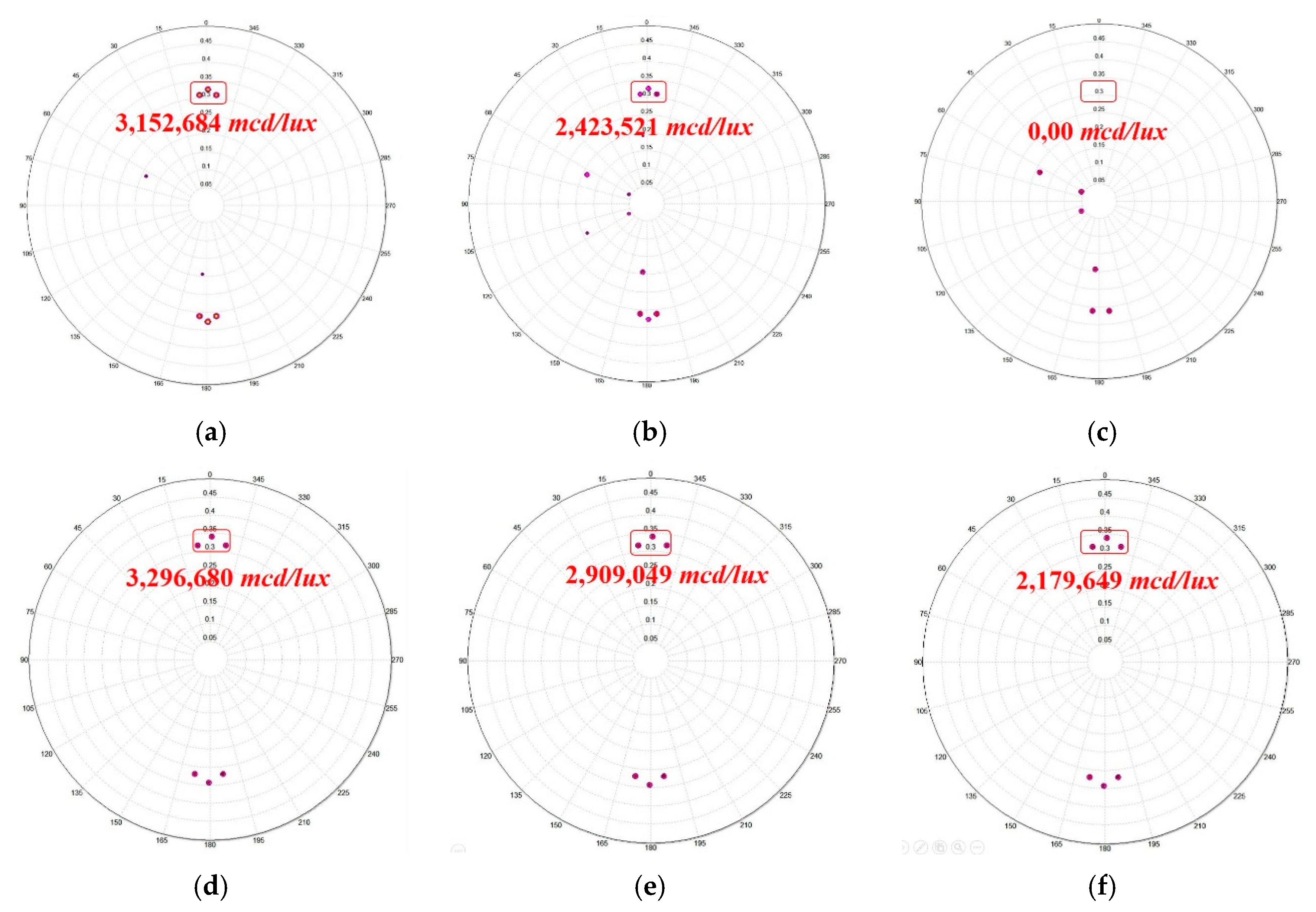
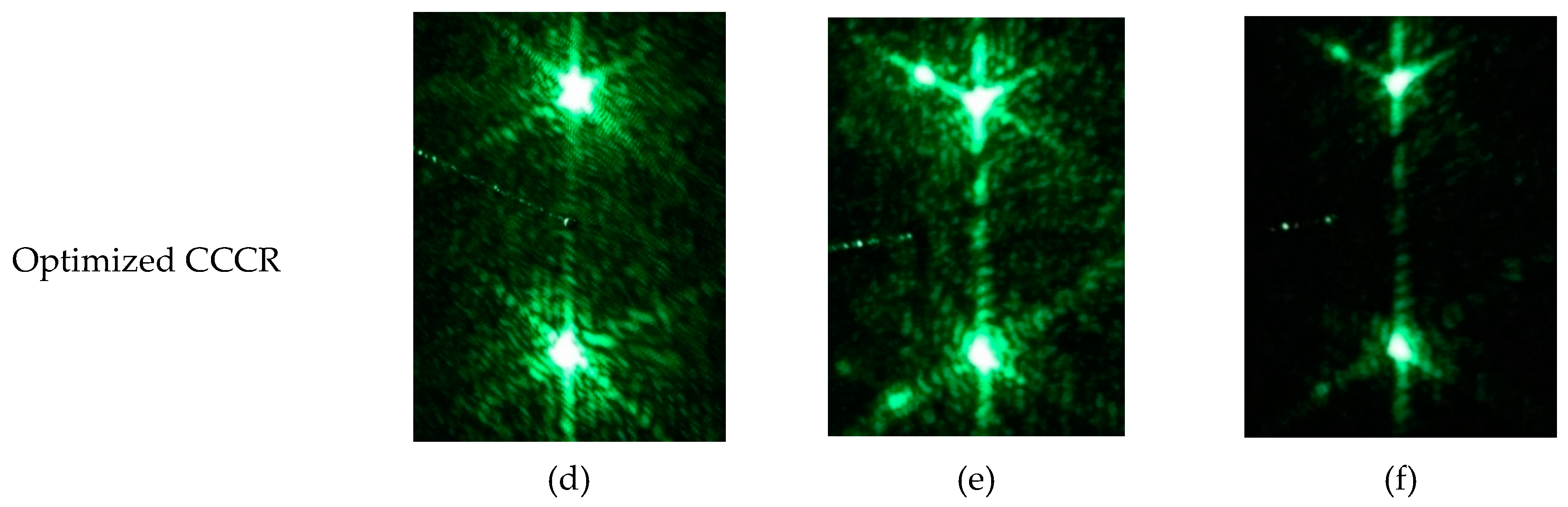
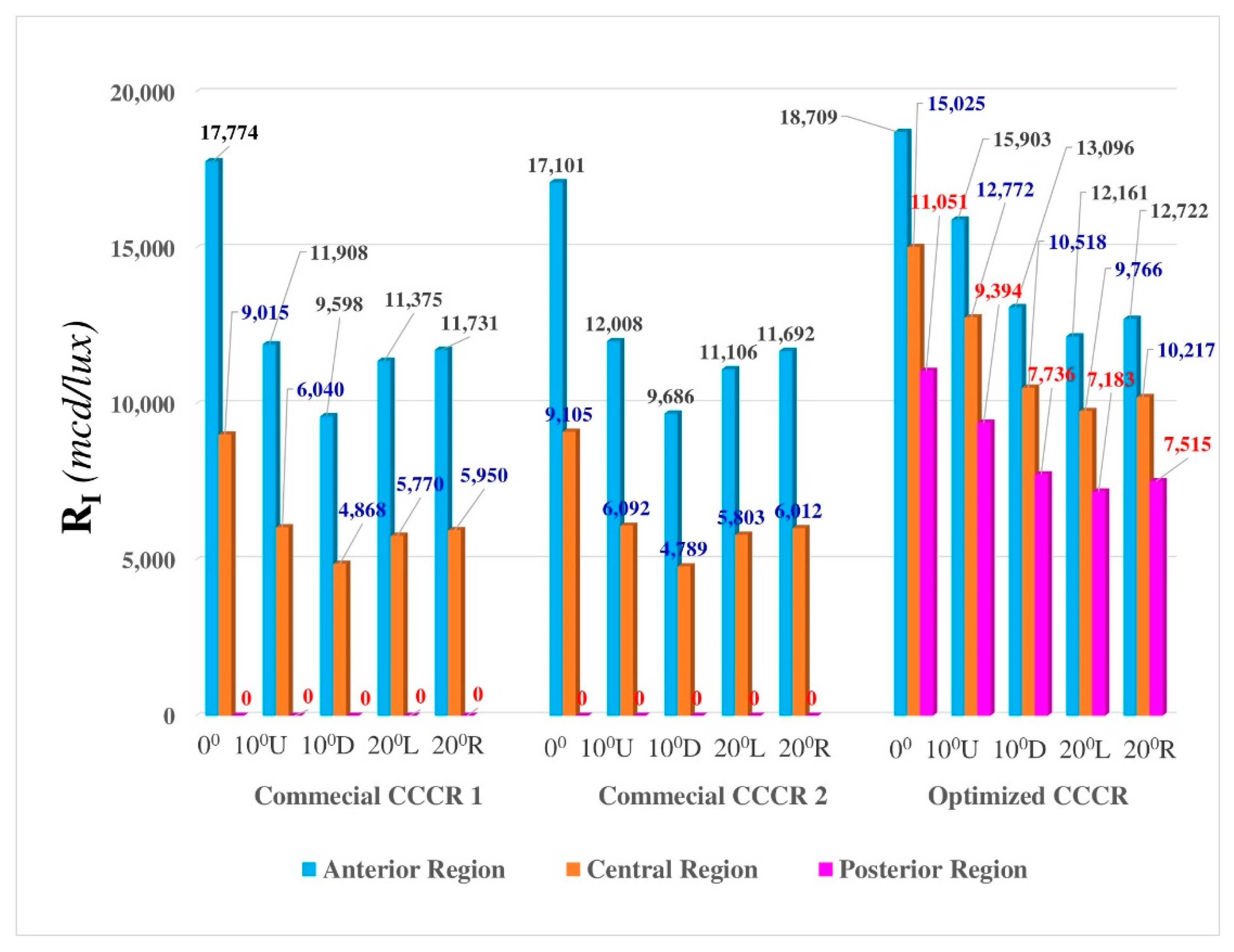
In order to demonstrate that the optimized SuperPin CCCR can really meet ECE requirements and perform better than the commercial samples, it is prototyped and tested in practical experiments, as shown in
Figure 20. Through the proposed experimental setup in
Figure 7, the retro-reflected outputs on the screen by two commercial CCCRs with the same part number (commercial CCCR 1 and commercial CCCR 2) and the optimized CCCR are presented in
Figure 21 while the resulting
RI values in rotational angles of 0°, 10°U, 10°D, 20°L, 20°R are obtained through optical measuring and shown in
Figure 22. At the posterior area of the two commercial CCCR samples, it could be found that their
RI values were both 0 mcd/lux. However, the
RI of the optimal CCCR sample was shown to be much improved. According to the bar chart shown in
Figure 22, the
RI values of the optimal CCCR sample at 0°, 10°U, 10°D, 20°L, 20°R are 11,051 mcd/lux, 9394 mcd/lux, 7736 mcd/lux, 7183 mcd/lux, and 7515 lux/mcd, respectively, and they were all over EU ECE regulation standards.
5. Conclusions and Discussions
A new optimal CCCR design which improves the performance and working area of the previous commercial one is proposed. We have demonstrated that the parameter of height difference between pin groups in a CCCR unit has an impact on the reflected light performance. In experiments, the curved retroreflector with a 120 × 28 mm reflecting area was built by 15 arrays of double-pin groups, and each pin cross-section size is 5.56 mm. It is demonstrated that a SuperPin CCCR can retro-reflect one incident beam as six beams, as shown in
Figure 5c. If a CCCR has a curved region, the height between each group of pins due to surface curvature would affect optical characteristics, leading to lower reflection efficiency and even failing to pass ECE regulations. By using double-pin groups to build the primary SuperPin CCCR, reflection efficiency can be improved. Through using OptisWork software to find out the optimized SuperPin CCCR,
RI can be increased further, but by sacrificing reflection efficiency
RA, as shown in
Figure 18 and
Figure 19. Using an efficient working area ratio, reflection efficiency
RA and coefficient of luminous intensity
RI as the evaluation indices of CCCR to compare a commercial SuperPin CCCR with the proposed new design, it can be inferred that the optimized SuperPin CCCR redistributes the reflected light beam energy of the primary SuperPin CCCR, which shares more energy into the 0.33° up-reflected beam by taking energy from the other five reflected beams. After computer simulations and optical experiments, it is demonstrated that the proposed SuperPin CCCR is not only above the ECE standard but also has a 33% larger working area and much better reflection efficiency than the commercial one, whose posterior region is not effective at all, as shown in
Figure 18 and
Figure 19. Based on the data in
Figure 22, it can be computed that the ratio of averaged
RI of the optimized SuperPin CCCR to that of the commercial CCCR is (14929/8930, 0°), (12689/5983, 10°U), (10450/4822, 10°D), (9704/5715, 20°L) and (10152/5894, 20°D), which means 40.1% (0°), 52.85% (10°U), 53.05% (10°D), 41.1% (20°L), and 42% (20°R) higher retro-reflection efficiency can be accomplished by the proposed SuperPin CCCR.
One of the most important advantages of this research outcome is that the new design of the SuperPin CCCR can enhance transportation safety. On the other hand, to produce our proposed design with the highest accuracy and optimal efficiency, it is essential to have an advanced CNC (computer numerical control). Consequently, the commercial price of this design will be slightly higher than previous ones.
In conclusion, we proposed a curved reflex reflector with a new cube-corner structure. By using genetic algorithms for optimization, the angles and the positions of the pins considered as building elements of corner-cube reflectors can enhance the performance of a curved reflex reflector. Compared with conventional retro-reflectors, it is found that a 46% higher retro-reflection efficiency and 33% larger working area can be accomplished with our optimized design. The yield rate of the mold production of the optimized design is less than the commercialized design because, through the pin composition method, the precision of the pin height control is even more necessary. In order to overcome the technical problems, we are conducting a study into molding by ultra-high precision casting.

 ,
, 