Article

Packet Switching Strategy and Node Architecture of Extended Spectral-Amplitude-Coding Labels in GMPLS Networks

School of Electrical and Computer Engineering, Nanfang College of Sun Yat-Sen University, Guangzhou 510970, China
Appl. Sci. 2019, 9(7), 1513; https://doi.org/10.3390/app9071513
Submission received: 31 January 2019 / Revised: 5 April 2019 / Accepted: 8 April 2019 / Published: 11 April 2019
(This article belongs to the Special Issue Photonic Switching)

Abstract

:
We present packet switching applications based on extended spectral-amplitude-coding (SAC) labels in generalized multi-protocol label switching (GMPLS) networks. The proposed approach combines the advantages of wavelength-division multiplexing (WDM) and optical code-division multiple access (OCDMA). The extended SAC labels preserve the orthogonal property to avoid the effect of multiple access interference (MAI) shown at the decoder. We investigate the node architecture of label generation/recognition based on arrayed waveguide grating (AWG). Combining cyclic-shifted maximal length sequence (MLS) codes with the wavelength routed property of AWG simplifies the node structure. The simulation results show that the proposed labels achieve good performances against receiver noise due to the low average cross-correlation values. Under a given bit-error-rate (BER), the switching efficiency of the extended SAC labels outperforms the previous OCDMA schemes, as the network nodes are capable of processing a large number of labels simultaneously.

1. Introduction

In recent years, generalized multi-protocol label switching (GMPLS) networks have become mature in practical applications and deployments in metropolitan area networks (MANs) [1,2,3]. Much of the attention to GMPLS comes from the integration of internet protocol (IP) layers and the optical switching paradigm. By merging several layers to form a single control plane, the network provides a reliable system with reduced complexity. In the network, packets are optically switched in time, wavelength, or space domain along the paths connected by nodes. Due to the packet-based structure, GMPLS is perfectly compatible with optical packet switching (OPS) [4,5,6], which overcomes the processing delay in the electrical switching mechanism.
The development of high-speed optical code-division multiple access (OCDMA) systems inspires researchers to implement optical codes as labels in GMPLS [7,8,9]. OCDMA labels are proposed to provide finer granularity in bandwidth utilization than their wavelength-division multiplexing (WDM) counterpart. Labels represented by optical codes are stacked in a common channel to make full use of the available bandwidth. In GMPLS, packets are forwarded along a label switching path (LSP) consisting of connections between nodes. Label distribution protocol (LDP) distributes the labels to all node connections and stores the assignments in a look-up table. To acquire the optimal LSP, LDP searches the look-up table and analyzes all possible paths from the packet source to destination. When OCDMA labels are adopted in the network, a small-size table can be employed to reduce the packet processing time.
Spectral amplitude coding (SAC) is a remarkable way to implement OCDMA labels due to its system simplicity [10,11,12]. As SAC labels are encoded on the optical spectrum, the components of label generator and processor can be operated at a relatively low chip rate without processing the high-speed payload bits. Multiple access interference (MAI) is the main bottleneck in OCDMA systems, resulting from the overlapping wavelengths from different label signals. By using balanced detection and properly designed codes, SAC labels can be identified without MAI [13]. The recent development of grating components, such as fiber Bragg grating (FBG) and array waveguide grating (AWG), reduces the system cost of label implementation. In reference [10], SAC labels generated from a nonlinear effect named four-wave mixing (FWM) were experimentally demonstrated. A unique FWM wavelength was recognized as an identifier to achieve fast label processing. To remove the complex procedures of label swapping and label inserting, label stacking is presented in reference [11]. The authors of reference [12] proposed two packet formats with stacked labels, packets with isolated SAC labels and with SAC payloads. The experiment demonstrated that the packets with two stacked SAC labels were successfully switched in a two-node, 80 km-long network.
As residential and industrial users develop in the metropolitan area, the MAN scale increases. The packets carry more SAC labels to travel a longer distance to reach the destinations. However, increasing the label number in the stack induces phase intensity-induced noise (PIIN), which is a dominant element limiting the performance of label recognition [14]. Optical code pattern is the main factor highly correlated with the PIIN variance. Optical codes with low-cross correlation are designed to suppress receiver noise [15]. We have previously introduced stuffed quadratic congruence (SQC) codes as SAC labels in reference [16]. Due to the ideal cross-correlation value, a large number of labels can be attached to packets to increase the transmission distance. However, constructing these codes requires complicated mathematical processes, and the code types are limited.
The hybrid WDM/SAC scheme is an alternative method to improve network performance by reducing the PIIN effect [17,18]. The related research was limited to an access network [17] and fiber sensor [18]. Although SAC labels have been widely employed, fewer previous studies investigated WDM/SAC labels for packet switching in GMPLS networks. The existing WDM code switched networks are mostly based on time-spreading codes [19], which have completely different properties from SAC. Time-spreading OCDMA requires strict synchronization between the transmitter and receiver. The decoder has to be operated at the high chip rate to detect the short pulses.
In this paper, we present a scheme of extended SAC labels for packet switching in GMPLS networks. This approach combines the advantages of WDM and OCDMA techniques. WDM networks have low network complexity, while OCDMA networks benefit from the high efficiency of bandwidth utilization. The extended SAC labels preserve the orthogonal property so that the effect of MAI shown at the decoder can be neglected. The extended SAC labels have lower cross-correlation values than the conventional labels for a given code length. Thus, the proposed labels have a good performance against PIIN. The node architecture to achieve simple processes of label generation/recognition is also investigated. We select a maximal length sequence (MLS) codes [20] with the cyclic-shift property to implement the optical labels. By combining MLS codes with the wavelength-routed property of arrayed waveguide grating (AWG), the node structure can be simplified. We employ numerical simulations to show the effectiveness of the proposed labeling scheme. To quantify the system performance, the power spectral density (PSD) of the stacked labels is analyzed to calculate the bit-error rate (BER).
The rest of this paper is organized as follows. Section 2 outlines the construction processes of extended SAC labels and investigates their correlation properties. Section 3 illustrates the packet switching strategy and label distribution scenarios. Section 4 describes the node architecture for generating/recognizing the extended SAC labels. Section 5 analyzes network performance by calculating BER. Finally, Section 6 presents a conclusion.

2. Processes of Constructing Extended SAC Labels

In this section, we constructed extended SAC labels and analyzed their correlation properties. A SAC code family is characterized as (N, ω, λ) where N is the code length, ω is the code weight, and λ is the cross-correlation value. The extended SAC label E(i, j) can be generated from MLS codes of {N, (N + 1)/2, (N + 1)/4} according to the following mapping procedure:
E ( i , j ) = C ( i ) [ 0 _ 0 _ 1 _ j - th   matrix 0 _ 0 _ ] _ total   M   matrixes , 1 < i < N , 1 < j < M
where C(i) is the i-th vector of MLS code, 0 and 1 are the vectors of all N elements being zeros and ones, ⊗ is the Kronecker multiplication symbol, and M is the WDM channel number. Table 1 shows an exemplary label set of extended SAC labels with N = 3 and M = 3. The main idea is to divide the label vector into M blocks. For label E(i, j), MLS code C(i) is located in the j-th block, while other N(M-1) chips are all zeros. Compared with the conventional OCDMA labels, the code length of extended SAC labels is increased from N to L, where L = MN.
From the mapping procedure of (1), label length L can be varied by assigning different values to M and N. We can adjust the available label number to match the connection number in GMPLS networks. For conventional SAC labels, the label numbers are limited to several discrete code lengths. For example, the code lengths of MLS codes are defined as 2p-1, where p is an integer larger than one. When MLS codes are used as optical labels, the label number for a network may be redundant or insufficient. On the other hand, the extended SAC labels are more flexible so that they can be applied to networks of different scales. Table 2 compares the available lengths of MLS and the proposed extended labels.
Next, we investigated the correlation properties of E(i, j) to evaluate the label quality effectively. Cross-correlation λ is defined as the number of overlapping chips between any two codes in a code family. As optical codes with large λ suffer serious PIIN effects at the decoding end [15], λ should be minimized or reduced when OCDMA labels are designed. The correlation values between two extended SAC labels are defined as follows:
E ( i ,   j ) E ( k , l ) = { N + 1 2 ,    i = k , j = l . N + 1 4 ,    i k , j = l . 0 ,        otherwise .
where ⊙ denotes the dot-product symbol [21]. From (2), any two labels with different indexes j are orthogonal and have zero correlation value. For any two labels with the same index j, the correlation properties are similar to the ones of MLS codes. The cross-correlation of the extended SAC labels is defined as follows:
λ = 1 M N l = 1 M k = 2 N E ( 1 , 1 ) E ( k ,   l )
Figure 1 shows the average correlation of the extended SAC labels for different code lengths. For similar L, λ is decreased with M. The larger M is, the more zeros are included in the code vectors, so the overlapping chips between two labels are reduced. For cross-correlation expressions, extended SAC and MLS labels are similar, where λ = (N + 1)/4 and λ = (L + 1)/4, respectively. As N is always smaller than L when M ≥ 2, the extended labels (M = 2, 4) have a smaller λ than that of MLS labels (M = 1). For example, E(1,1) and E(1,2) in Table 1 have L = 6 and λ = 2, respectively, while the cross-correlation of MLS codes with L = 7 is double (λ = 4).

3. Packet Switching Strategy and Label Distribution Scenario of Extended SAC Labels

In this section, we adopt the concept of label stacking and extended SAC labels to achieve packet switching applications in GMPLS networks. Label stacking is applied to optical networks by attaching multiple labels to a single packet. The LDP determines an LSP linked from the packet source to the destination according to the forward information. The connections along the LSP correspond to a set of extended SAC labels. When a packet arrives, the network nodes analyze the label stack to make a switching decision. Then, the node controls an optical switch to guide the packet to the correct path. Label stacking simplifies the computational complexity of packet switching as it avoids label removing and label inserting. The only required function for each node is to recognize a specific label from the stack.
Figure 2 shows a schematic diagram of a GMPLS network with extended SAC labels. The network nodes are divided into two categories: edge node and core node. Edge nodes set up an LSP and insert the corresponding labels to a packet. Core nodes analyze the label stack and determine the switching path. There are two LSPs in this network, which are denoted as LSP 1 and LSP 2. Each connection in the LSPs corresponds to an extended SAC label. For LSP 1, packets pass through three connections, which map labels E(1,1), E(2,1), and E(3,2). Edge node 1 attaches these labels to packets before sending them to the network. When packets reach core nodes, the optical labels are converted to electrical signals for decoding. Except for label recognition, packets stay in the optical domain during the switching process, which solves the mismatch between electrical signals and optical components.
Figure 3a shows the time waveform and power spectral density (PSD) of an optical packet traveling along LSP 1. In this example, the packet’s payload, represented by four data bits (1,1,0,1), is modulated on an optical carrier with on-off keying (OOK). For bit “1” an optical pulse carrying stacked SAC labels is transmitted, while a zero message is sent for bit “0.” The label stack is a synthesizing vector {1, 2, 1, 1, 0, 1, 0, 0, 0}, which comes from the summation of E(1,1), E(2,1), and E(3,2). As the SAC scheme is employed, the label stack is represented by a wavelength distribution of {λ1, 2λ2, λ3, λ4, 0, λ6, 0, 0, 0}. The simulations were conducted with Optisystem. The power and bandwidth of the light source are set to −10 dBm and 0.3 THz, respectively. Two light sources centered at 193 THz and 193.4 THz are employed to generate the labels with j = 1 and j = 2. The bit rate is 10 GB/s and the chip width of the SAC labels is 0.1 THz.
Figure 3b shows the packet signals traveling along LSP 2. The payload energy is lower than that of Figure 3a, as only two labels, E(3,1) and E(2,2), are carried in a single bit. The labels corresponding to LSP 2 are not overlapping, due to the proper label assignment and path selection. When a label stack is constructed, the labels with distinct values of j are preferred to reduce the overlap on wavelengths. Different LSPs result in different labels in a stack. For a long LSP, a large number of labels are included in a packet, and wavelength superposition becomes inevitable. Therefore, balanced detection is adopted in the node architecture to recognize the desired label without MAI.

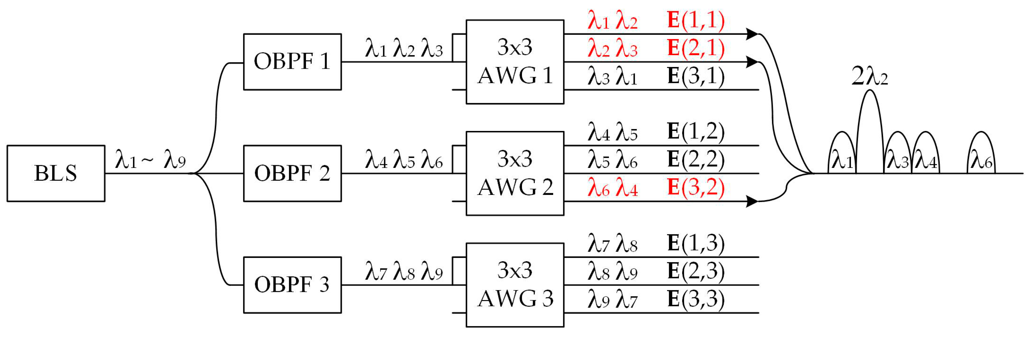
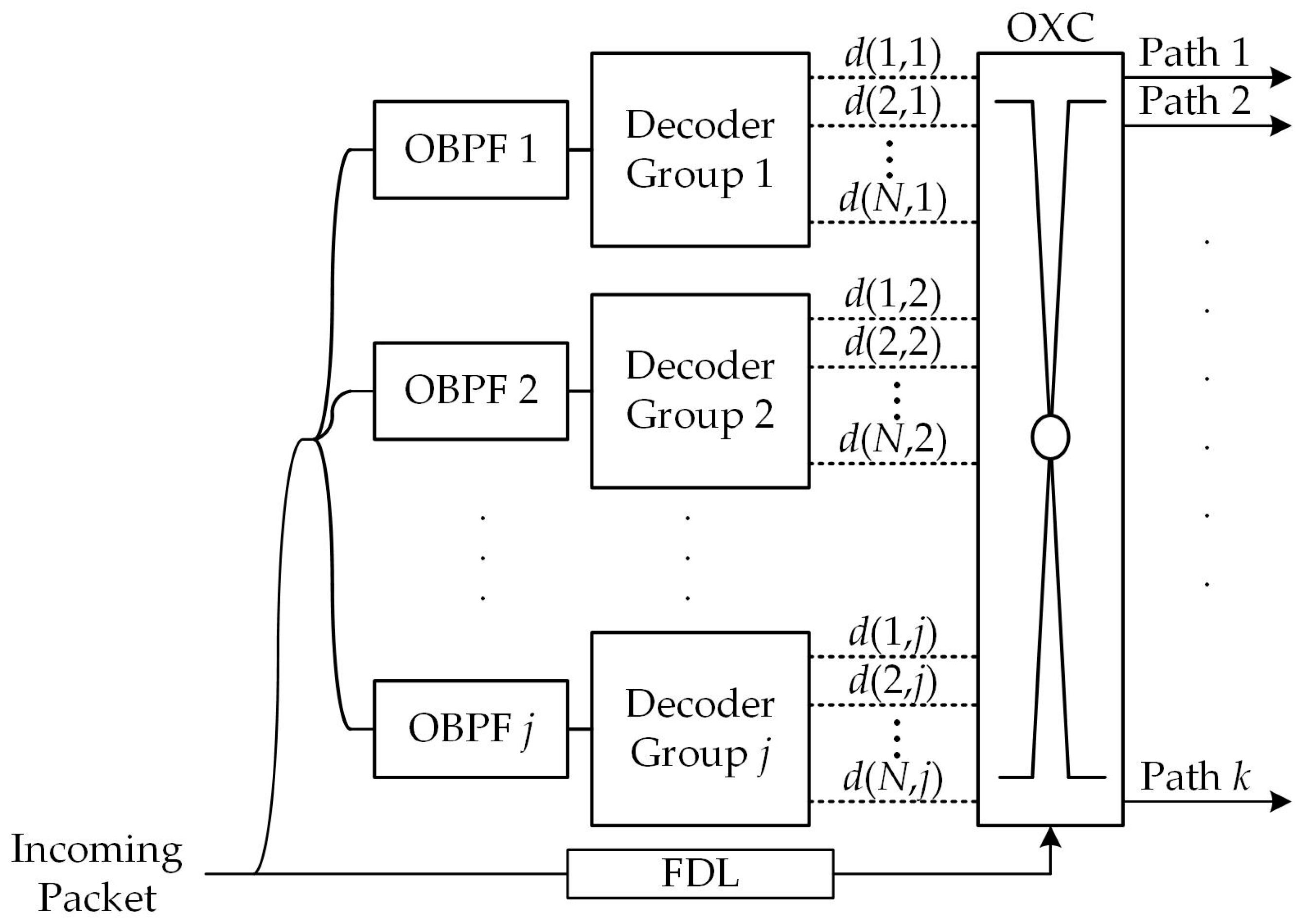
4. Node Architecture of Extended SAC Label Generation and Recognition

The edge node architecture for generating extended SAC labels in GMPLS networks is shown in Figure 4. Edge nodes transfer the path information of packets into a label stack. A broadband light source (BLS) is coupled to M optical band-pass filters (OBPFs) to construct M WDM channels. Each OBPF has an equal bandwidth but different central frequencies. Encoder group j encodes MLS codes C(1), C(2),…, C(N) on the j-th WDM channel to generate labels E(1, j), E(2, j),…, E(N, j). An optical cross-connect (OXC) establishes the connections for the labels required for packet switching. Finally, an optical coupler aggregates the labels to form a stack. A Mach–Zehnder modulator (MZM) modulates the payload bit stream on the intensity of stacked labels.
The label generation scheme of the proposed extended labels (N = 3, M = 3) is shown in Figure 5. We use MLS codes of (N = 3, ω = 2, λ = 1) as the label basis. Three MLS codes are defined as C(1) = (1,1,0), C(2) = (0,1,1), and C(3) = (1,0,1), respectively. Note that C(i + 1) is the cyclic-shift vector of C(i) for one chip. The wavelength signals in channel j enter the first and second input ports of AWG j for encoding. The selection of AWG ports (port 1 and port 2) corresponds to the positions of chip “1s” in MLS code (1,1,0). For E(1,1) = (1,1,0,0,0,0,0,0,0), it is generated at the first output port of AWG 1 and represented by a wavelength distribution of {λ1,λ2,0,0,0,0,0,0,0}. Based on the wavelength-routed property of AWG, E(2,1) and E(3,1) are shown at the second and third output ports of AWG 1, which are represented as {0,λ2,λ3,0,0,0,0,0,0} and {λ1,0,λ3,0,0,0,0,0,0}, respectively. We take the example of label distribution of LSP1 in Figure 2, where the connections in LSP1 match labels of E(1,1), E(2,1), and E(3,2). Therefore, an OXC switches these three signals to a coupler for label stacking. The wavelength components in the stack signals are the summation of the three individual labels.
The architecture of the core node with extended SAC label recognition is shown in Figure 6. Core nodes switch and forward packets based on the decoded signals of stacked labels. For simplicity, we demonstrate a node structure with a single input port and k output ports. An optical splitter separates the received packet into two signals with an identical waveform but only half of the power. One of the signals is split into j streams and sent to j OBPFs for label decoding, while the other is queued in a fiber delay line (FDL). After label recognition is performed, the decoded signals d(i, j) of extended labels E(i, j) control an OXC to switch the packet to the correct path. Note that the setups of OBPFs and decoder groups are varied based on the path connections to the core node.
Figure 7 shows the process of label recognition based on an AWG decoder. In this example, we demonstrate the packet switching process along LSP 1 at core node 4 in Figure 2. The decoder structure includes a pair of AWGs and two balanced detectors connected to the AWG outputs. The decoded signal d(i, j) used for identifying E(i, j) can be derived by performing correlation subtraction expressed as follows.
E ( i ,   j ) E ( k ,   l ) - E ¯ ( i , j ) E ( k , l ) = { N + 1 2 ,   i = k , j = l . 0 ,         i k , j l .
where E ¯ ( i , j ) is the complementary code of E(i, j). As E(2,1) is included in the label stack, the decoded signal d(2,1) has a relatively high amplitude. Then, a link to the path corresponding to E(2,1) is set up to finish packet switching.

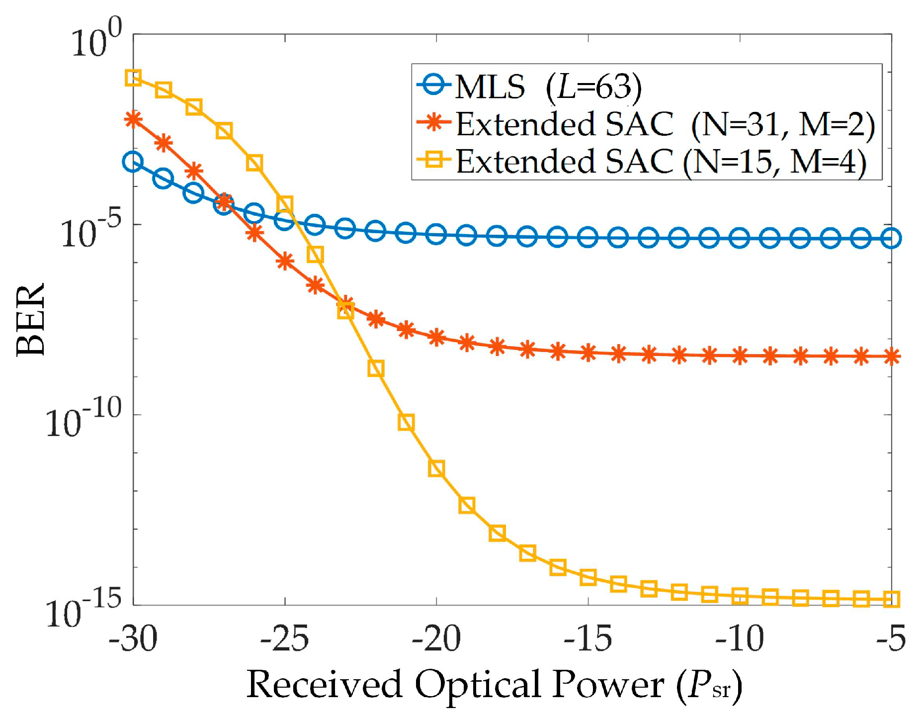
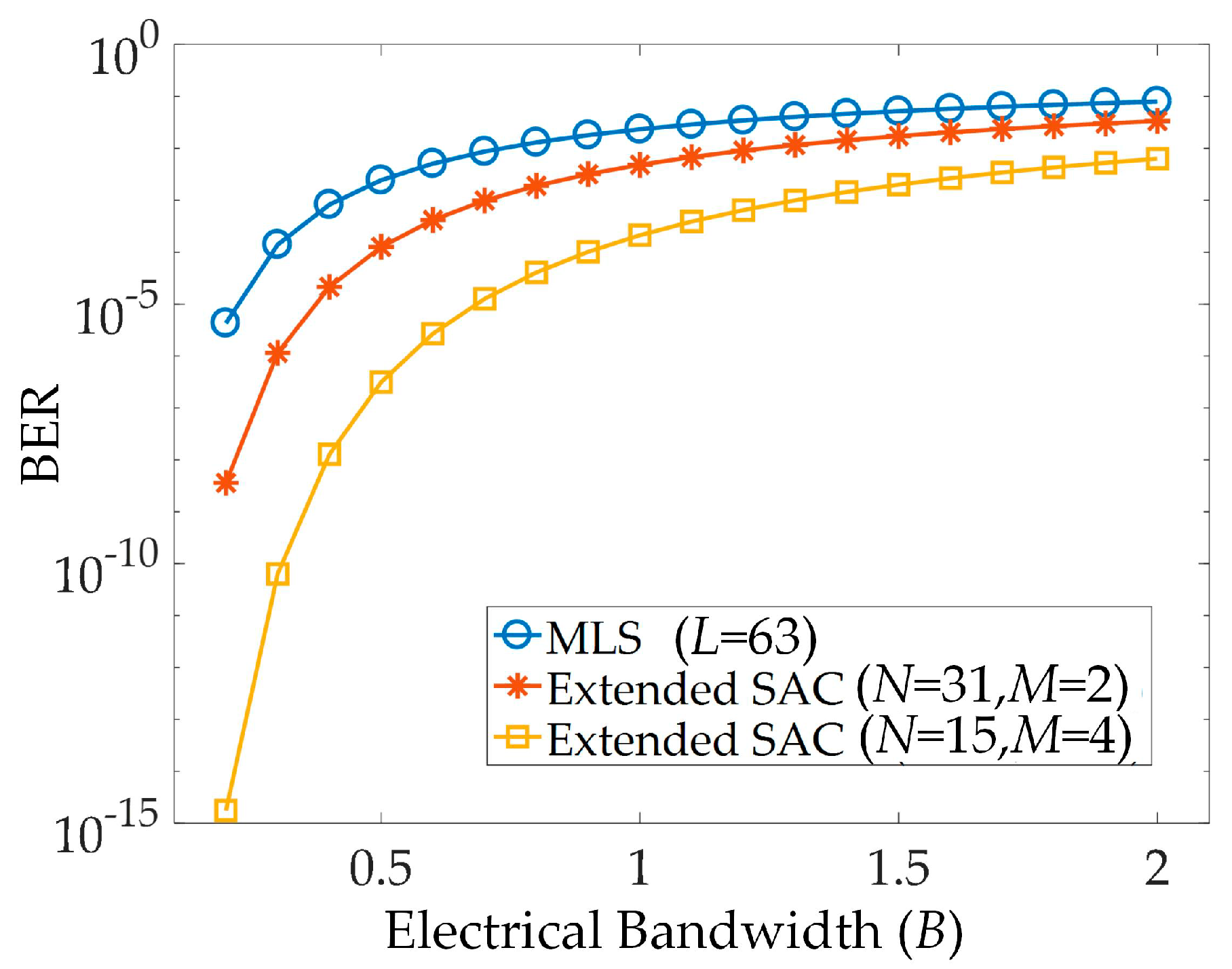
5. Performance Analysis and Discussion

In this section, we employ numerical simulations to quantify the system performance in BER. The BLS for generating the extended SAC labels is centered at λc and has a flat spectrum over bandwidth v. OBPFs for de-multiplexing M WDM channels have a bandwidth of v/M and central frequency of λc-v (2j-1-M)/2M, where j = 1, 2,…, M. AWGs with the channel spacing of v/MN and free spectral range (FSR) of v/M are used to generate N labels in each channel. We consider the packet -switching process of decoding label E(1,1) from the label stack. Using the definition in reference [22] and the correlation property of (2), the photocurrent I generated from decoding the optical label is expressed as follows.
I = [ E ( 1 , 1 ) E ¯ ( 1 , 1 ) ] i = 1 κ E ( i , 1 ) = R P sr M N ( N + 1 ) 2
where R denotes the photodiode responsivity, Psr is the received optical power, and κ is the effective label number. When a label is converted from an optical to electrical signal by a balanced detector, PIIN, thermal noise, and shot noise are the dominant performance degradations. The mathematical expression of PIIN variance σ PIIN 2 is deducted as follows.
σ PIIN 2 = R 2 P sr 2 B M N v [ E ( 1 , 1 ) + E ¯ ( 1 , 1 ) ] [ i = 1 κ E ( i , 1 ) j = 1 κ E ( j , 1 ) ] = R 2 P sr 2 B M N v [ ( N + 1 ) 2 κ + ( N + 1 ) 4 κ ( κ 1 ) ] = R 2 P sr 2 B ( N + 1 ) 4 M N v κ ( κ + 1 )
where B is the electrical bandwidth. The thermal noise and shot noise variance are defined as:
σ Th 2 = S Th B
σ Shot 2 = 2 e B I = e B R P sr ( N + 1 ) M N
where STh is the PSD of thermal noise in W/Hz and e is the elementary charge of a single electron. When E(1,1) is decoded, only the extended SAC labels with the index i = 1 enter the decoder, while the OBPF removes the labels of i ≠ 1. The relation between the effective label number and the total label number K is described as follows.
κ = K M + 1
where . denotes the floor function. Since the payload bits are modulated in OOK, the label stack only presents when bit “1” is sent. The BER PB is written as
P B = 1 2 π σ I / 2 e ( x I ) 2 / 2 σ 2 d x = 1 2 erfc ( I 2 2 σ )
where σ 2 = σ PIIN 2 + σ Th 2 + σ Shot 2 , which denotes the total noise variance.
Figure 8 shows the BER comparisons of two labeling scenarios in GMPLS networks. Parameters used for numerical simulations are Psr = −10 dbm, R = 0.95 A/W, B = 200 MHz, λc = 193.4 THz, v = 3.75 THz, and STh = 6.4 × 10⁻²⁴ W/Hz. For a given stacked label number K, the BER values for extended SAC labels are smaller than MLS labels. The reason is that the number of overlapping chips between labels is reduced by adding zeros to extend the code vector. Furthermore, varying the code length only causes a slight difference in system performance. However, the labels with a long code length are suitable for switching packets in a large-scale network, as the number of path connections in the network is relatively large.
Figure 9 shows the relationship between BER and the received optical power at the core node’s decoder for K = 15. At low power levels, both MLS and extended labels suffer from thermal noise and the performance of MLS labels is slightly better due to a relatively large photocurrent. When the power level increases, the BER improvement of extended SAC comes from the small average cross-correlation, which has a less contribution to PIIN. Under similar code lengths, the labels with a larger M, which has a greater ability to suppress PIIN, obtain better BER than the ones with a smaller M.
Due to the increasing signal rate in networks, the decoder requires a large bandwidth to meet this demand. Figure 10 shows the relationship between BER and the electrical bandwidth for K = 15 and Psr = −10 dBm. The result shows that BER increases with B, which reveals that a high signal rate is obtained at the expense of a large noise variance in the receiver’s bandwidth. Similar to the tendency shown in Figure 8 and Figure 9, the proposed labels show lower BER when the code length is fixed. Therefore, employing extended SAC labels for packet switching is more suitable for achieving high-speed transmissions in GMPLS.
In Figure 8, Figure 9 and Figure 10, the value of M is carefully chosen to achieve good BER performance. However, the stacked label number K or the LSP length may vary in different networks. Figure 11 investigates the impact of channel number on the system signal-to-noise ratio (SNR) for K = 10, 20, and 40. The lengths of extended labels L are set close to 127. The optimal set for designing extended SAC labels for K = 40 is (N,M) = (7,64). Although increasing the channel number can reduce PIIN variance, it lowers the photocurrent at the same time. When K is sufficiently small, and the PIIN effect is not notable, a large value of M may lead to system degradation due to the low SNR. This analysis is very helpful in designing a label set for GMPLS networks of various sizes.

6. Conclusions

In this paper, we proposed a label set known as extended SAC labels for packet switching in GMPLS networks. The proposed scheme combines the advantages of SAC-OCDM and WDM. WDM schemes have low network complexity, while OCDMA schemes benefit from the high efficiency of bandwidth utilization. The extended SAC labels preserve the orthogonal property so that the effect of multiple access interference (MAI) shown at the decoder can be neglected. We investigated the node architecture to achieve simple processes of label generation and recognition. The simulation results show that the proposed labels achieve better BER performances against receiver noise than the conventional OCDMA labels due to the low average cross-correlation values. Furthermore, the optimal channel number was analyzed to reach the maximum SNR for a specific number of stacked labels.

Funding

This research received no external funding.

Conflicts of Interest

The authors declare no conflict of interest.

References

  1. Kanj, M.; Rouzic, E.L.; Meuric, J.; Cousin, B.; Amar, D. Optical power control in GMPLS control plane. IEEE/OSA J. Opt. Commun. Netw. 2016, 8, 553–568. [Google Scholar] [CrossRef]
  2. Farghal, A.E.; Shalaby, H.M.H.; Kawasaki, Z. Multirate multiservice all-optical code switched GMPLS core network utilizing multicode variable-weight optical code-division multiplexing. IEEE/OSA J. Opt. Commun. Netw. 2014, 6, 670–683. [Google Scholar] [CrossRef]
  3. Huang, S.; Baba, K.; Murata, M.; Kitayama, K. Architecture design and performance evaluation of multi-granularity optical networks based on optical code division multiplexing. IEEE/OSA J. Opt. Commun. Netw. 2016, 5, 1028–1042. [Google Scholar] [CrossRef]
  4. Segawa, T.; Ibrahim, S.; Nakahara, T.; Muranaka, Y.; Takahashi, R. Low-power optical packet switching for 100-Gb/s burst optical packets with a label processor and 8 × 8 optical switch. IEEE/OSA J. Lightwave Technol. 2016, 34, 1844–1850. [Google Scholar] [CrossRef]
  5. Zhao, Z.; Wu, B.; Li, B.; Xiao, J.; Fu, S.; Liu, D. Multihop routing enabled packet switching with QoS guarantee in optical clos for data centers. IEEE/OSA J. Opt. Commun. Netw. 2018, 10, 624–632. [Google Scholar] [CrossRef]
  6. Lopez, V.; Hernandez, J.A.; De Dios, O.G.; Palacios, J.F.; Aracil, J. Multilayer traffic engineering for IP over WDM networks based on Bayesian decision theory. IEEE/OSA J. Opt. Commun. Netw. 2010, 2, 515–529. [Google Scholar] [CrossRef]
  7. Beyranvand, H.; Salehi, J.A. All-optical multiservice path switching in optical code switched GMPLS core networks. IEEE/OSA J. Lightwave Technol. 2009, 27, 2001–2012. [Google Scholar] [CrossRef]
  8. M’Sallem, Y.B.; Seddighian, P.; Rusch, L.A.; LaRochelle, S. Optical packet switching via FWM processing of time-stacked weight-2 codes. IEEE Photonics Technol. Lett. 2008, 20, 1712–1714. [Google Scholar] [CrossRef]
  9. Farnoud, F.; Ibrahimi, M.; Salehi, J.A. A packet-based photonic label switching router for a multirate all-optical CDMA-based GMPLS switch. IEEE J. Sel. Top. Quantum Electron. 2007, 13, 1522–1530. [Google Scholar] [CrossRef]
  10. Rosas-Ferna’ndez, J.B.; Ayotte, S.; Rusch, L.A.; LaRochelle, S. Ultrafast forwarding architecture using a single optical processor for multiple SAC-label recognition based on FWM. IEEE J. Sel. Top. Quantum Electron. 2008, 14, 868–878. [Google Scholar] [CrossRef]
  11. Chen, K.S. Label stacking scenarios in hybrid wavelength and code-switched GMPLS networks. Electronics 2018, 7, 251. [Google Scholar] [CrossRef]
  12. Seddighian, P.; Ayotte, S.; Rosas-Fernandez, J.B.; Penon, J.; Rusch, L.A.; LaRochelle, S. Label stacking in photonic packet-switched networks with spectral amplitude code labels. IEEE/OSA J. Lightwave Technol. 2007, 25, 463–471. [Google Scholar] [CrossRef]
  13. Chen, K.S. Advancing high-speed transmissions over OCDMA networks by employing an intelligently structured receiver for noise mitigation. Appl. Sci. 2018, 8, 2408. [Google Scholar] [CrossRef]
  14. Shalaby, H.M.H. Performance analysis of SAC-OCDMA systems adopting overlapping PPM schemes. IEEE/OSA J. Lightwave Technol. 2013, 31, 1856–1866. [Google Scholar] [CrossRef]
  15. Yang, C.C. Optical CDMA passive optical network using prime code with interference elimination. IEEE Photonics Technol. Lett. 2007, 19, 516–518. [Google Scholar] [CrossRef]
  16. Chen, K.S.; Yang, C.C.; Huang, J.F. Using stuffed quadratic congruence codes for SAC labels in optical packet switching network. IEEE Commun. Lett. 2015, 19, 1093–1096. [Google Scholar] [CrossRef]
  17. Yang, C.C. Hybrid wavelength-division-multiplexing/spectral-amplitude-coding optical CDMA system. IEEE Photonics Technol. Lett. 2005, 17, 1343–1345. [Google Scholar] [CrossRef]
  18. Cheng, H.C.; Wu, C.H.; Yang, C.C.; Chang, Y.T. Wavelength division multiplexing/spectral amplitude coding applications in fiber vibration sensor systems. IEEE Sens. J. 2011, 11, 2518–2526. [Google Scholar] [CrossRef]
  19. Khattab, T.; Alnuweiri, H. Optical CDMA for all-optical sub-wavelength switching in core GMPLS networks. IEEE J. Sel. Areas Commun. 2007, 5, 905–921. [Google Scholar] [CrossRef]
  20. Yang, C.C.; Huang, J.F.; Tseng, S.P. Optical CDMA network codecs structured with M-sequence codes over waveguide-grating routers. IEEE Photonics Technol. Lett. 2004, 16, 641–643. [Google Scholar] [CrossRef]
  21. Horn, R.A.; Johnson, C.R. Matrix Analysis, 2nd ed.; Cambridge University Press: Cambridge, UK, 2012. [Google Scholar]
  22. Wei, Z.; Shalaby, H.M.H.; Ghafouri-Shiraz, H. Modified quadratic congruence codes for fiber bragg-grating-based spectral-amplitude-coding optical CDMA systems. IEEE/OSA J. Lightwave Technol. 2001, 19, 1274–1281. [Google Scholar]
Figure 1. Average cross-correlation value λ of extended SAC labels versus code length L.
Applsci 09 01513 g001
Figure 2. Packet switching over a generalized multi-protocol label switching (GMPLS) network with extended SAC labels.
Applsci 09 01513 g002
Figure 3. Time waveform and power spectral density (PSD) of an optical packet traveling along (a) LSP 1; (b) LSP 2.
Applsci 09 01513 g003aApplsci 09 01513 g003b
Figure 4. Edge node architecture for generating extended SAC labels.
Applsci 09 01513 g004
Figure 5. Structure of generating extended labels (N = 3, M = 3) using maximal length sequence (MLS) codes and arrayed waveguide grating (AWG).
Applsci 09 01513 g005
Figure 6. Core node architecture with extended SAC label recognition.
Applsci 09 01513 g006
Figure 7. Packet switching process based on recognizing extended labels using an arrayed waveguide grating (AWG) decoder and correlation subtraction.
Applsci 09 01513 g007
Figure 8. Bit-error-rate (BER) versus the number of stacked labels for MLS and extended SAC labels.
Applsci 09 01513 g008
Figure 9. BER versus received optical power for MLS and extended SAC labels.
Applsci 09 01513 g009
Figure 10. BER versus electrical bandwidth for MLS and extended SAC labels.
Applsci 09 01513 g010
Figure 11. Signal-to-noise ratio (SNR) versus the channel number M for different K.
Applsci 09 01513 g011
Table 1. Extended spectral-amplitude-coding (SAC) label set of M = 3 and N = 3.
jiE(i, j)
11110000000
2101000000
3011000000
21000110000
2000101000
3000011000
31000000110
2000000101
3000000011
Table 2. Comparison of available label numbers of maximal length sequence (MLS) code and extended SAC label.
Code LengthNumber of Available Label Lengths
MLS CodeExtended SAC Label
<1024
<2039
<30314
<40421
<50427
<60431
<70538

