1. Introduction
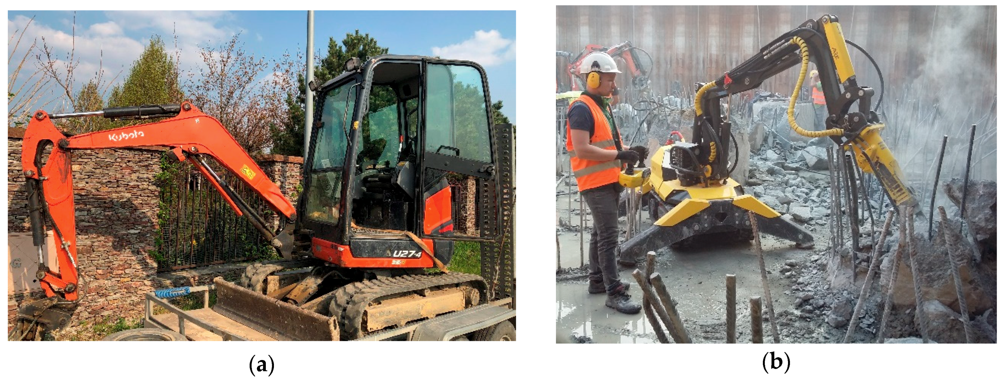
In construction and deconstruction works, staff and machinery are exposed to difficult conditions, such as high temperature, ground collapses, landslides, noise, dust, mud, and radioactive contamination. An increasing variety of construction projects carried out over the years, also in wintertime, indicates a demand for the latest technology with maximum process reliability. Apart from difficult working conditions, there is an increasing number of accidents in which operators and people in general are harmed and which result from unskilled machine operation or loss of stability. When operating a machine, experienced operators understand the capabilities of their machine (its maximum tilt, the reach of the arm, etc.) before it loses stability, i.e., tips over because of an unfavorable tilt angle. If the machine is operated in conditions unknown to the operator, there is an increased risk of it exceeding the permissible work limits and thus losing stability. Hence, we increasingly hear about machines overturning unexpectedly, especially excavators—mini diggers. In order to protect the operator from injury in such accidents, protective structures that meet specific requirements are built for machines with an operator cabin or operator seated on the machine. Examples of such structures include Roll-Over Protective Structures (ROPS), which protect the operator in the event of a machine overturning, and Falling Object Protective Structures (FOPS), which protect the operator from falling objects [
1,
2,
3]. An example of a mini-excavator with a protective structure is shown in
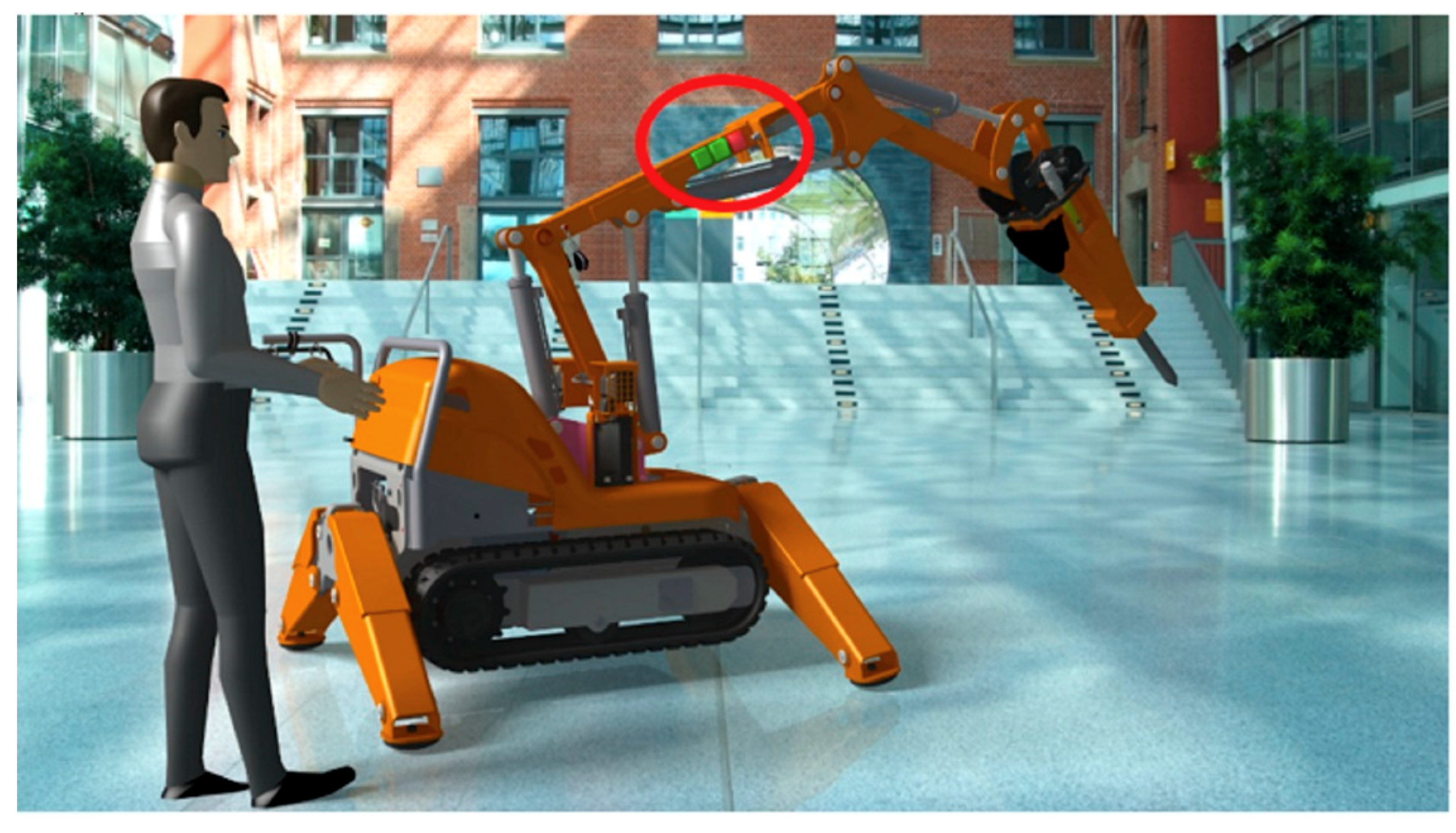
Figure 1a, while
Figure 1b shows a remote-controlled demolition robot with the operator standing next to the machine. In the latter case, without the knowledge of the machine’s behavior, the operator cannot sense the critical moment before overturning.
Because they offer the possibility for the operator to be outside the machine, remote-controlled demolition robots are often used in situations where operators are at a higher risk of injury, e.g., building demolitions, toxic environments, areas with the danger of nuclear contamination or places that are difficult to access by the operator, such as narrow silos of a cement plant [
4,
5]. On the one hand, this improves the safety of human beings but, on the other hand, it eliminates the possibility for the machine to provide feedback related to the working conditions. This can be compared to what a driver experiences in his or her car, for instance the difference in vibration when driving on different types of surfaces or the momentum of the engine, the spinning of wheels, etc. Just as in the case of the driver who uses such information to drive safely, the operator needs it to operate a heavy machine, such as a demolition robot, without damaging it.
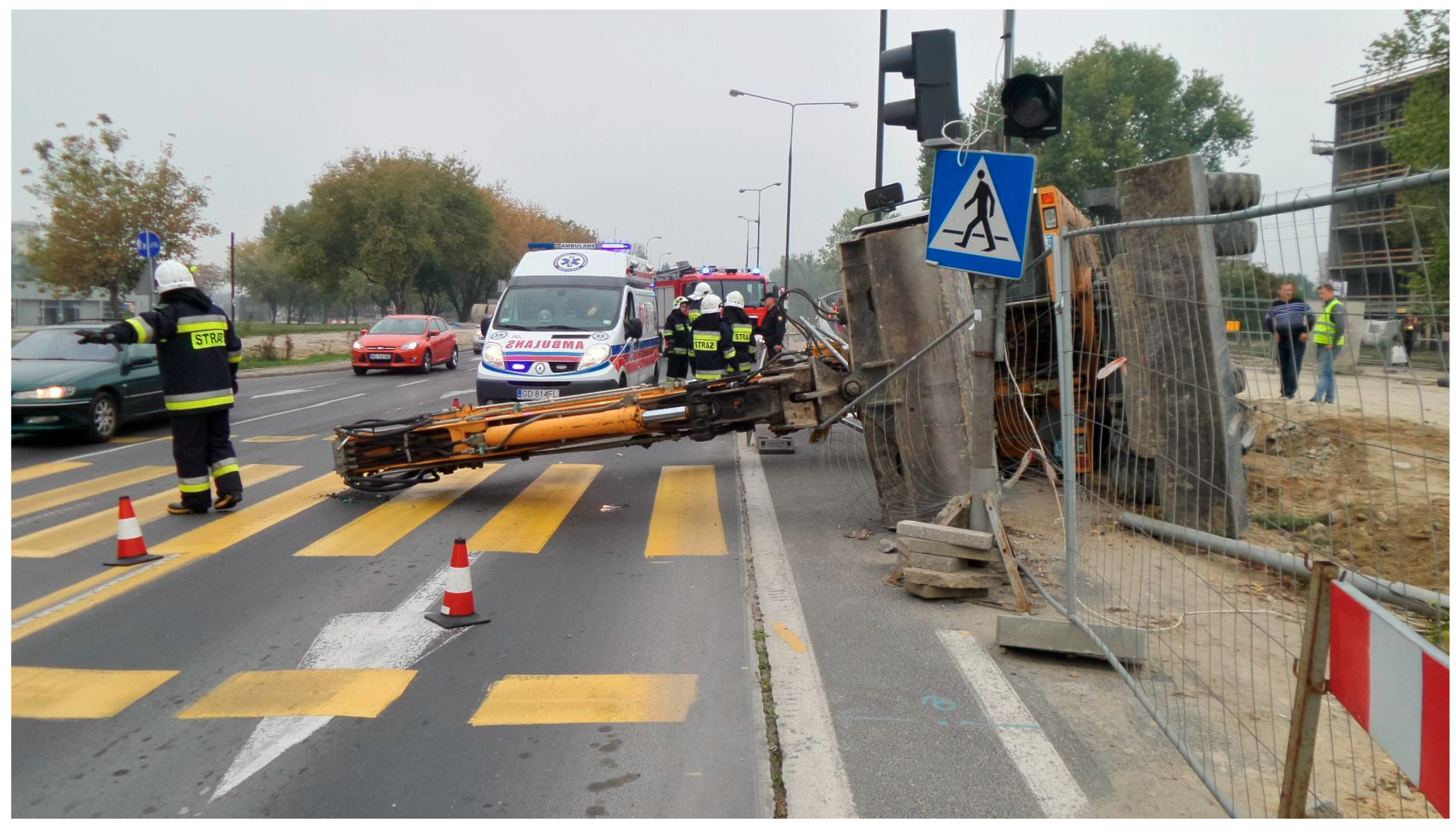
Figure 2 shows an example of excavator overturning because it exceeded the tilting angle during operation.
Figure 2 depicts an excavator that fell onto a pedestrian crossing and hit an accidental passer-by. The protective structure successfully protected the operator but the excessive tilt of the machine during operation contributed to this unfortunate accident.
A case study of machine overturning accidents as well as the application of the proposed design and construction method based on user research served as the basis for the development of an accident prevention system for heavy duty machines, with special focus on mini-diggers and remote-controlled demolition robots.
2. Design Process
The second half of the twentieth century brought a series of studies by authors such as Pahl and Beitz, Suha, French, Dietrich, Clarkson and Ullman [
7,
8,
9,
10,
11,
12,
13,
14] aimed at working out general theories of the design process. The main task of a design process theory is to provide an effective method for improving the quality of tasks performed by the design. The most general guidelines are created with the intention of making the design processes more effective.
There are many different descriptions of the design process and for instance, Pahl and Beitz conclude that the most challenging issue in design is making the creative leap between problem definition and solution [
9]. For instance, in the mechanical design literature, proposed by many authors, a common feature of methods is the emphasis placed on understanding the relation between the form and function of physical structures or mechanisms [
8].
In general, based on the works by authors such as French, Pahl, Beitz, and Ullman, the definition of the design process indicates that design applies to all stages of the process of satisfying the needs of end-users, and involves the following stages: structure design, material design, and technology design [
7,
8,
15,
16].
In the process of Engineering Design, a number of terms refer to the process which is employed to create, develop, and deliver the products to the market. These terms are technological innovation, product design, product development, product realization, invention, and engineering design. It should be noted that academics and practitioners often differ on the definitions of the above terms. Moreover, there are plenty of different models of the engineering design process but all of them include the following elements [
17]:
stage of need identification and analysis,
stage of conceptual design aimed at creating and developing new (innovative) ideas to satisfy the identified need,
stage of development of the concept aimed at transforming it into a full product or layout of the system,
stage of finalization of design details.
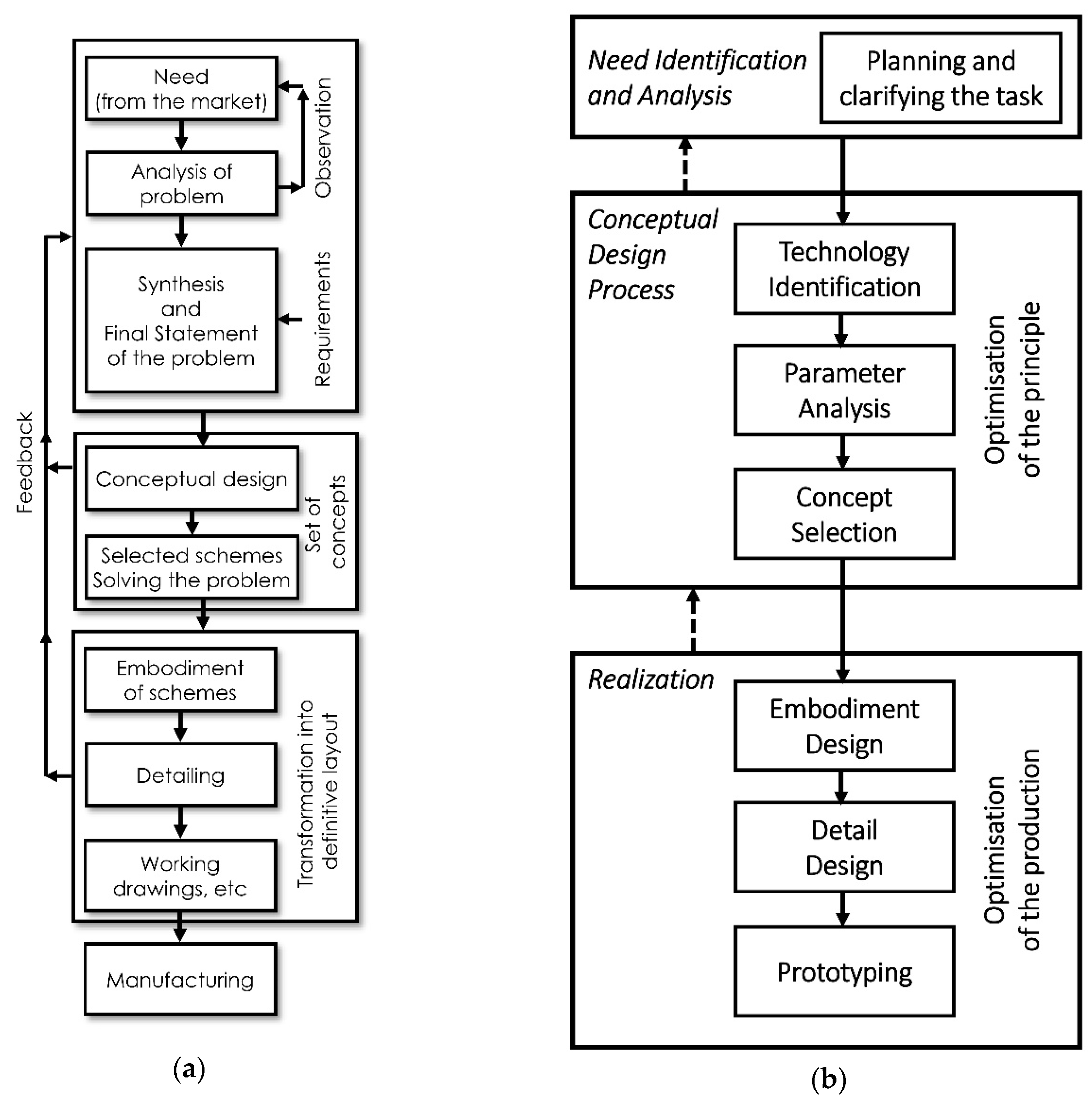
Based on the design practices observed in the industry, a general model of the engineering design process was proposed by French [
7,
8]. This model is a design-focused process that concerns the technical aspects of solutions to design problems and describes the necessary steps to progress from a problem to its solution. Some of the models are general in nature and have been applied in many designing disciplines, while others are more focused on the product structure and are less relevant outside the target discipline [
17].
Authors Pahl and Beitz proposed the concept of methodical design based on a stage-based implementation of the entire process. In the concept of Pahl and Beitz [
10], the stages are implemented one by one, sequentially, and include:
formulation of the design task,
preparation of a conceptual design,
preparation of a structural design,
preparation of the implementation project.
General views of the design process and engineering design process by French, Clarkson, and Eckert [
7,
8,
17] are represented by two flowcharts presented in
Figure 3.
As far as the industry application of design processes is concerned, it can be observed that several types of design processes are used [
11,
15,
18]:
design based on the selection of one of the available solutions; this is a typical situation when the company has a number of design solutions—designing consists in selecting the solution that is best-suited to a given situation,
design based on the configuration; as in the first case, solutions already exist; designing involves the selection of various elements and systems which must be related in a certain way,
parametric design; the parameters of selected attributes are changed in existing solutions,
original design; a new design is created from scratch,
design based on redesign; in this approach an existing structure is developed using various types of design mentioned above.
Design Thinking Methodology
In detail, the first stage in the designing process of a new solution/structure or in the process of optimizing an existing system is the process of recognizing the need or the set of needs, which are to be satisfied by a set of technical measures. This need or set of needs are formally written in the form of design and construction requirements. The design and construction requirements include the description of the nature of the activity, situational data, and quantitative data. However, the described needs do not always correspond to the actual needs of the user but are subjectively determined by the designer. As for the design of innovative solutions, or more precisely, inventions, or the sales potential of applicable solutions, the specific need must be consistent with the real need of the end-user or the customer. One of the methodologies that helps to investigate the needs of users is Design Thinking methodology [
19,
20,
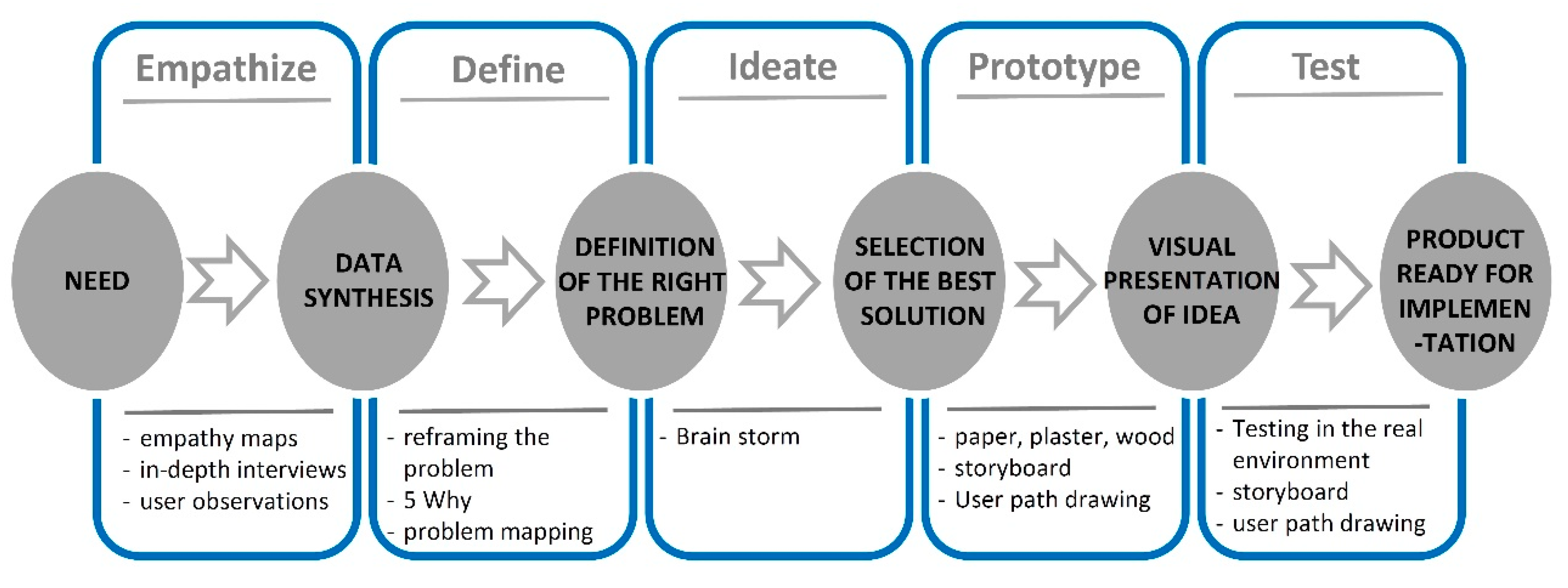
21], which is the first stage in the conceptual design phase of innovative solutions. Design Thinking (DT) is a methodology considered by many as a systematic process for creating innovative products and services based on a deep understanding of users’ problems and needs [
19]. Generally, the Design Thinking methodology consists in focusing on the user and understanding his unconscious and conscious needs. On an interdisciplinary team, all the problems can be viewed from many different perspectives. The analysis of the problem not only applies to the process of designing new solutions but also developing solutions based on incorrect requirements, causes of failures, or dangerous accidents. The DT methodology presented in
Figure 4 consists of five stages: Empathizing, Defining the problem, Generating ideas, Building rapid prototypes, and Testing [
19,
20].
3. Design and Construction Method Based on a Study of User Needs and the Operational System
When developing existing products or solutions that can be used in existing products to increase their functionality, to reduce the likelihood of failure and, most importantly, of an accident, two additional stages must be included before the empathizing stage:
EXPLORE—testing of the work environment, production and product use,
RESEARCH—market research and comparative analysis (a benchmark).
Given the complexity of the entire design and construction process related to the product life cycle and innovative solution design, and taking into consideration the design thinking methodology [
20,
21], additional stages should be introduced after the final stage of the DT methodology. In general, this extension of the DT methodology in the phase of delivery of the finished solution implements three stages after the Testing stage [
22]. For instance, Navigate [
22] expanded the delivery phase of DT by stages of build, measure, and sustain, which directly corresponds to the delivery of the solution to the market. As far as development of innovative solutions is concerned, the stage of concept engineering should also be implemented to provide a full spectrum of product/service development. With this taken into account, the proposed method consists of four stages, which are:
ENGINEER—engineering design process,
BUILD—construction/production (technology of manufacturing) process,
MEASURE—user testing phase process,
SUSTAIN—durability, maintenance, and finished product life processes.
These stages are strongly related to the full product life cycle and, depending on the design and engineering needs, may be freely implemented.
Figure 5 shows the complete design and construction method based on the real needs of the user or the environment in relation to the product life cycle. The method consists of eleven stages in three phases and extends the Design Thinking process.
The first stage of the method, in the understand phase, is EXPLORE. This stage concerns the process of studying the operational system, which consists of the use and service of a product, operational environment (environment, in which the machine operates), and production of the product. For example, in the case of analyzed heavy machinery, this study helps to determine the exact operational environment. Research is strongly related to the process of product operation, i.e., its use and service in a given system and environment. Through interviews with users, the process of exploration also helps to determine the potentially dangerous types of operating environments, such as unusual undermining, collapse of underground tunnels, underground lakes, watercourses, wet ground, etc. The study of heavy machinery carried out by the project team helped to identify cases of overturning, described in the previous chapter, resulting from improper use or random cases, such as ground collapse.
The next stage of the method is market research (RESEARCH), which in the case of these machines can be an analysis of solutions used in other machines or devices operating in specific conditions. In addition, a classical comparative analysis of machines of the same type should be performed (benchmark).
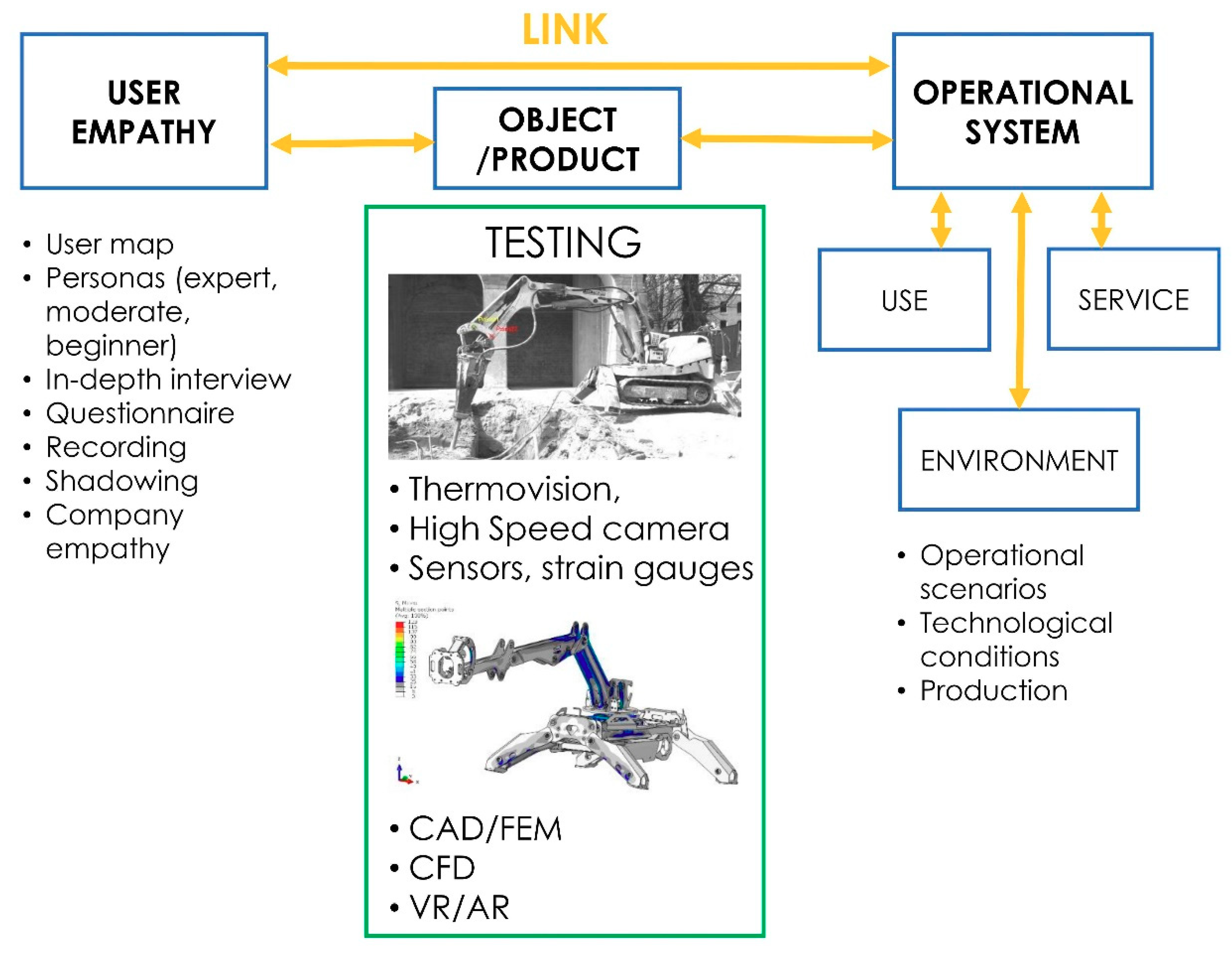
The research carried out in the first two stages may indicate the need to perform a more detailed analysis of the existing problem in the following step, which consists in empathizing (EMPATHIZE), i.e., the in-depth study of the machine user. During the understanding stage, which is the human-centered design process, a mind map is developed through in-depth user research by analyzing the user’s needs and problems. In this step, the researcher puts him or herself in the place of the end-user, and employs tools such as empathy maps, ethnographic interviews, user observations, reconnaissance surveys with a thorough analysis of the environment and needs in the context of functionality.
In order to define a design problem that pertains to the user’s unconscious needs and to increase the probability of developing a new product or its new functionality, it is necessary to link empathy research with the research of the operational system. This relation is presented in
Figure 6, which describes the tools for both stages of Explore (study of operating system) and Empathize. The following tools can be used to test the studied structure or product, as shown in
Figure 6: infrared camera, high-speed camera, sensors, such as accelerometers, strain gauges, or numerical methods such as Computer Aided Design using Finite Element Method (CAD/FEM), Computational Fluid Dynamics (CFD) as well as Virtual Reality (VR) or Augmented Reality (AR). This kind of link between the in-depth study of user needs and the analysis of operational system is a new contribution to the proper definition of the design problem or design requirement. The connection of the in-depth user study with the results of research on the operational system of the whole machine (environment, work modes, service) guarantees the identification of the problem and thereby the design of a solution that is easy to implement and distinguishes the proposed method from the existing models. The effects of the implementation of these stages of correlated research have been validated by a number of studies carried out by the author [
2,
4,
23,
24].
Tests on a demolition robot produced by one of the leading manufactures revealed that the needs are closely related to how the machine is controlled. The needs varied depending on whether the machine operator was seated in the operator’s cabin on the machine or was controlling the machine remotely. When analyzing heavy machinery it is crucial to recognize the hidden and intuitive motivations that may affect human choices and behaviors. This process is the empathize stage and consists in the study of user needs. It begins with the collection of requirements by means of ethnographic interviews, user observations, or site visits. In the case of the studied remote-controlled demolition robot, in-depth interviews were conducted with 60 users. By analyzing the type of the user, it was possible to define two important types of personas, namely the operator and the chief or owner of the machine. For both groups, special interview questionnaires were prepared with approximately 15 questions to gather the hidden user needs in the context of functionality. The questionnaire asked questions concerning the use of the demolition robot in typical situations or during incidents. For instance, operators were asked what they disliked about operating this particular machine or how they thought equipment affected the quality of their work. Among others, the users complained about poor stability, problems with steering, faulty tracks, or problems with the hammer being stuck in the material being demolished. The in-depth interviews with users resulted in empathy maps for each persona, defined as a collaborative visualization of what we know about a particular type of user [
18,
19,
20,
24]. The user research in combination with the analysis of the robot operational system, both of which were performed in accordance with the proposed method, provided a set of undefined and hidden needs that not only concerned the user but were also related to the operational system (use, service, and environment). One of the most important needs identified during the study was for the robot to provide information about its operating mode since the lack of such information could lead to machine failure, structure cracking, or machine overturning if an incorrect mode were engaged.
The next stage of the design phase consists in defining the problem (DEFINE). In this stage, the interdisciplinary team synthesizes the information collected during the Empathy stage in order to define the core of the problem. Emphasis is placed on thinking outside the box and approaching the problem from a different perspective. An appropriate identification of the problem will significantly affect the direction of the solutions sought. The problem that was identified in the study of remote-control demolition robots during operation was the possibility of their overturning through misuse (i.e., not as per manufacturer’s specification) or use by an inexperienced user who does not know the behavior of the machine. The next step in the method is idea generation (IDEATE), which consists of creating a range of possible solutions. This is a process, which requires great creativity and use of appropriate methods. Solutions are presented in an explicit, usually graphical form. Literature distinguishes three basic groups of conceptualization: intuitive, systematic, and algorithmic [
11,
18,
20,
21,
25].
The next stage involves building fast physical prototypes (PROTOTYPE). This idea is based on the ability to visually present ideas and find the final solution. The focus is not on creating a complicated model that is similar to the finished product but to quickly gather opinions on the idea.
The final stage of the design phase consists of testing the selected idea (TEST) in the target environment of the final product. The tested product can be implemented only when it is deemed to be the best by the customers. Only after the tests have been successfully completed can we say that the product or service is fully developed and ready for final implementation. This crucial stage is often overlooked in the implementation of many projects and ventures. As a result, after ideas and solutions that seem perfect on paper move to everyday use, it appears that they do not meet the required objectives and expectations of the end-users.
The next phase of the method is the implementation or delivery of the solution and it comprises four final stages: the engineering construction stage (ENGINEER), the construction-production stage of the solution (BUILD), the real user testing stage—product testing (MEASURE), the stage of durability and maintenance until the end of product life (SUSTAIN). All these four stages concern the product/solution delivery to the market by means of existing production technologies and capabilities.
4. Accident Prevention System for Heavy Duty Machines—A Case Study of Small Demolition Robots
The user research examined the needs related to the causes of accidents and failures of operating machines, in particular the cases of overturning and collapsing. Based on opinions of operators of this type of machines, site managers and accident assessors, the empathy stage, described in
Section 3, helped to determine a number of reasons why such events occur. As mentioned earlier, in the case of classic excavating machines with an operator’s structure in the form of a cabin or a protective bar, acceptance tests require that the structure meets certain standards [
1,
2]. Nevertheless, there are many events in which the machine turned over with the operator inside and fell onto an area where other people were present, for example a pedestrian crossing (see
Figure 2b). In a number of situations, the operator cannot react quickly enough to avoid an accident. Examples are shown in
Figure 2. In the case of machines under study, in particular small demolition robots, the operator is located outside the machine at a safe distance determined by him or herself. In demolition projects, the machine sometimes operates at the upper limit of the working range [
23,
26]. Most often stability is lost, when the working arm is extended to its maximum, despite the extended outriggers.
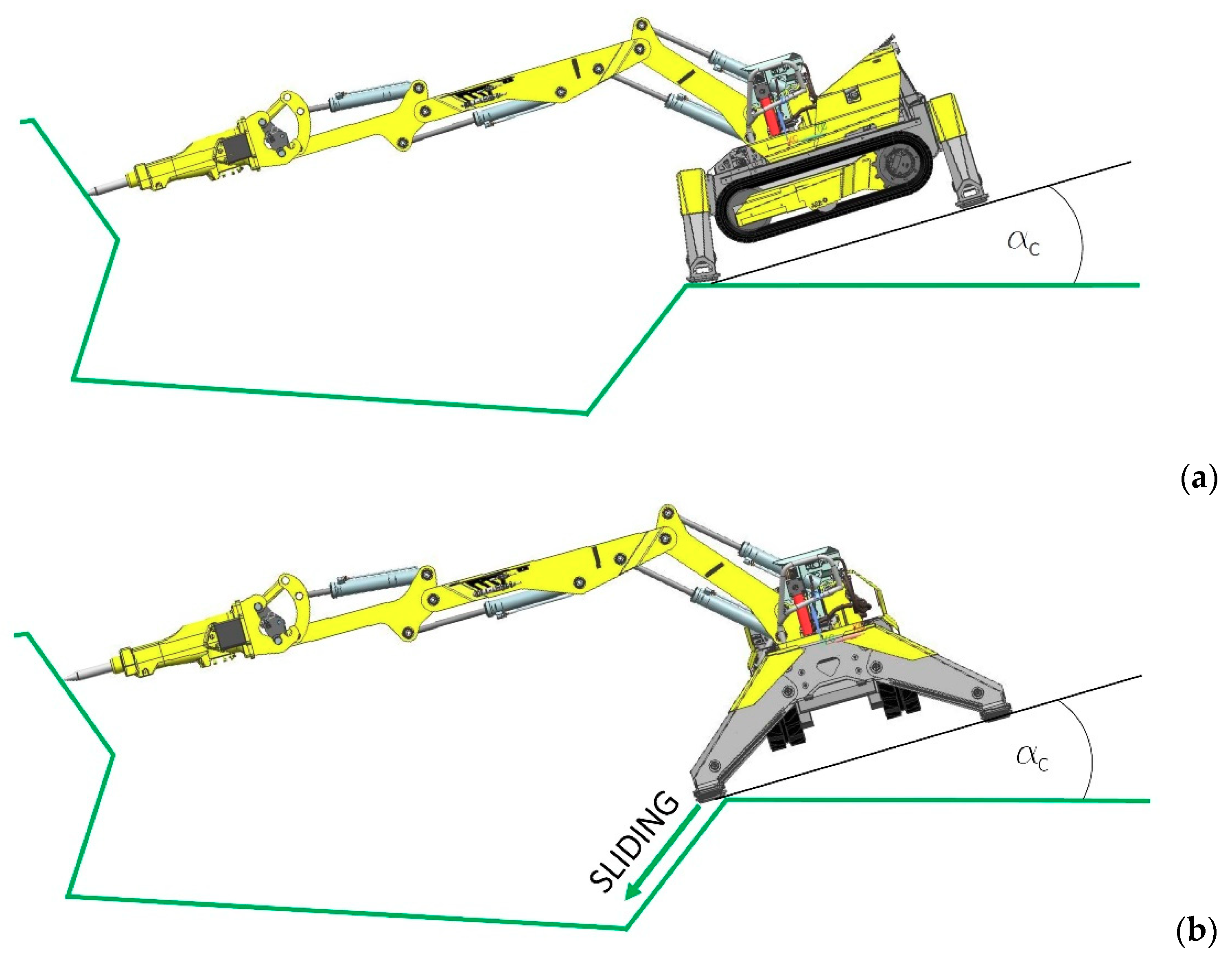
Figure 7 shows the maximum tilting angle α
C and if it is exceeded, the machine overturns, especially in certain cases of digging or hammering resulting from a fault of the operator.
In
Figure 7, this angle has been determined for two machine arrangements: (a) the longitudinal position of the working arm in relation to the chassis, and (b) the chassis rotated by 90° with respect to the working arm. As shown in
Figure 7b, in cases with extended outriggers the pressure of outriggers on the ground is so large that the edge of the ground under the outriggers fails causing the machine to slide down the slope. Similar cases also occur when the ground collapses or ruptures. The angle depends both on the maximum tilt of the machine but also on the angle of the ground under the machine.
The user research surveys, linked with the analysis of the operational system in the form of in-depth ethnographic interviews with excavator operators helped to identify states in which such events occur. This research made it possible to design a system that supports the operator’s work and enables him to react quickly in the event of an accident (machine overturning or sliding). This information is of particular importance to operators of remote-controlled machines because in most cases they have no feedback from the machine about its operating status [
27]. This information corresponds to what was obtained in the empathy stage (
Section 3), i.e., the need to have information about the robot’s operating mode.
For this purpose, experimental tests of the robot’s working mode were carried out, which helped to determine the modes with high risk of loss of stability and cases of faulty machine operation [
28,
29,
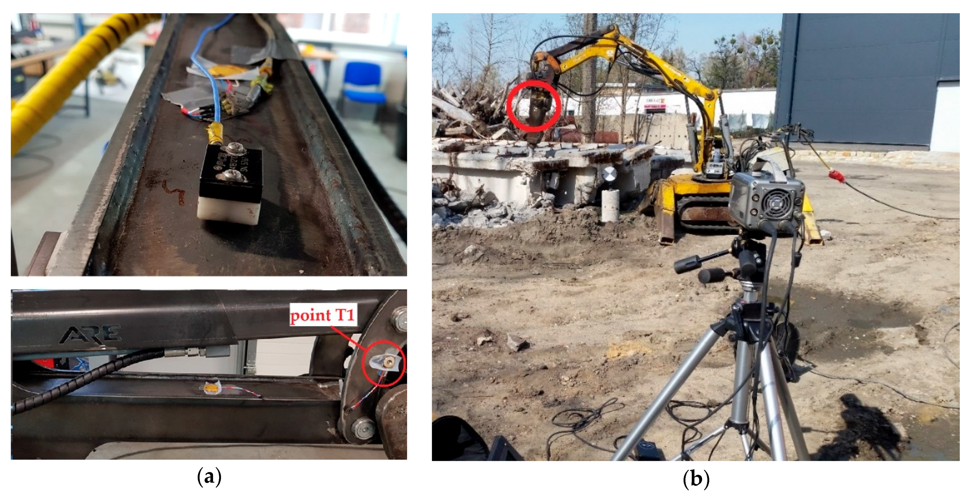
30]. Experimental research was carried out with the application of vibration and position sensors, strain gauges, as well as using images recorded by a high-speed camera.
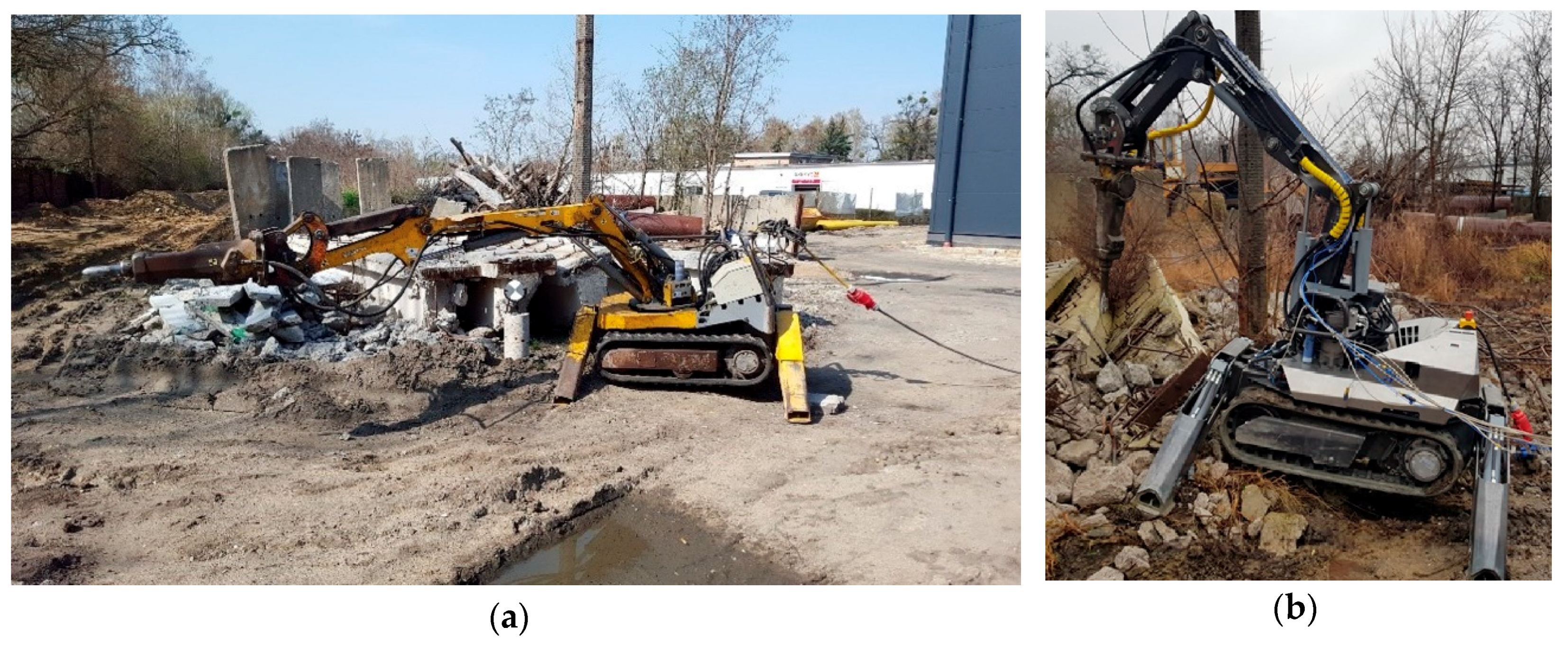
Figure 8 illustrates the experimental tests on the operating robot with different positions of the working arm. The figure shows one position in view (a), where the working arm is stretched out to the furthest possible point and the second positon in view (b), where the robot uses the hammer to demolish a concrete structure close to the machine. The tests revealed that when the machine is equipped with particular types of hammers it is not fully stable at the tilting angle of α
C = 0°, which indicates that in situations where the level of the ground is at a higher angle than 0°, the robot can overturn towards the front.
Such cases commonly result in accidents. For machines with a cabin, the function of protecting the operator is performed by the protective structure [
1,
2,
28], while in the case of remote-controlled robots the operator must pay attention not to crush or hit the machine.
The basis for the use of an HMI (Human–Machine Interface) is constant access to live-data recorded during (de-) construction works performed by the demolition robot [
27,
31]. Measurements and several runs with a Commtest VB7 vibrometer were also performed during the tests to determine values for external loads acting on the robot arm. The data obtained from sensors in the experimental tests were used to estimate the worst cases when an accident can occur, which could be very significant for accident prevention. To collect similar information about acceleration spectra in single, pre-defined measurement points while the robot was operating, a test run was also performed with the Phantom V12 high-speed camera at 2000 frames per second. The location of sensors and the high-speed camera measurements are shown in
Figure 9. The results of experimental tests should be combined with the results of numerical simulations based on the discrete model of the demolition robot (CAE—computer-aided engineering) [
28,
30]. The calculations performed with the application of the Finite Element Method could be a part of additional research [
23], which could provide additional data about the machine condition and high stress cases that can lead to machine failure [
23].
The results can be assessed by means of TEMA Motion, which shows the data collected in the first operation mode on waveforms for displacement, velocity. and acceleration in the aforementioned pre-defined measurement points on the demolition robot. The test run depicted above was performed for two different, but most common operating modes of the demolition robot: the first one is when the robot operates at optimal performance. The second mode of operation requires heavy duty hammering, but the hammer is not properly located inside the material that is being demolished. This represents a case when the positioning of the robot is suboptimal relative to the material that is being demolished or a case immediately after destroying the material when the tip of the hammer has to be repositioned. This operation can excite heavy vibrations in the machine [
23,
29], which can also propagate in the material and cause the machine to slide down the excavation pit.
To compare the aforementioned data for both modes of operation a visualization generated in National Instrument LabVIEW is combined with the readout from TEMA Motion.
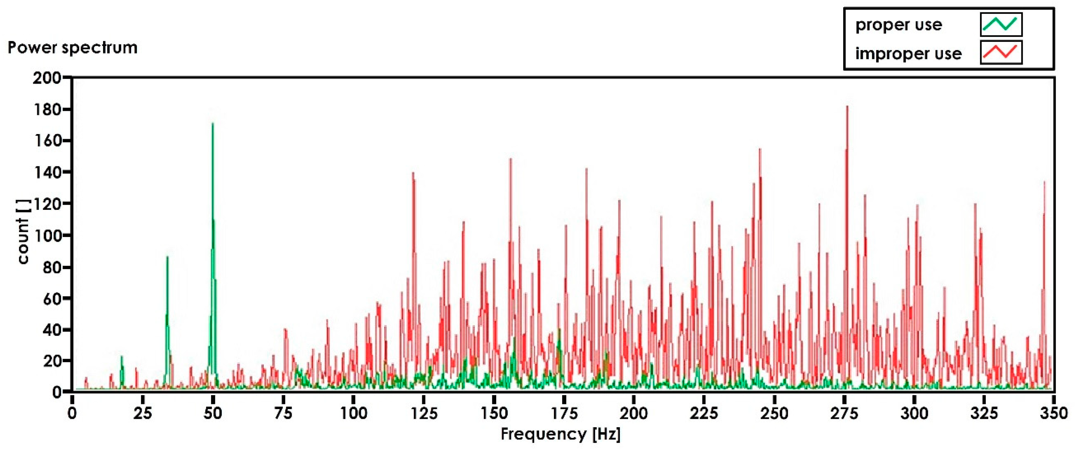
Figure 10 shows the time graph of acceleration for the pre-defined point on the hydraulic hammer (presented in
Figure 9b) during proper and improper use of the tool. The spectrum analysis can provide information to the operator about the improper use of the robot. This can help to correct the arm positioning in order to increase the working efficiency as well as to decrease the risk of machine failure resulting from operation in unfavorable conditions.
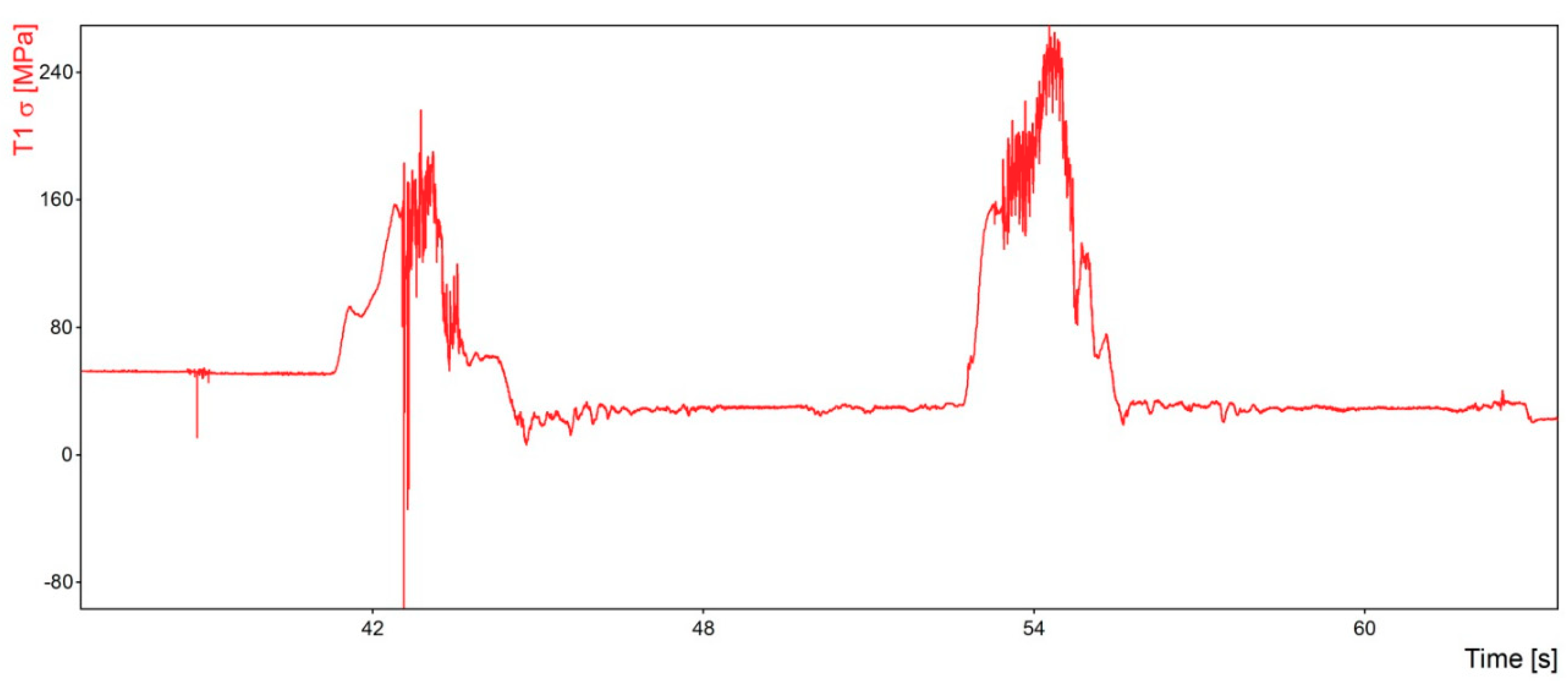
Apart from accelerometers, the testing system was also equipped with classical strain gauges. The data obtained from the strain gauges helps to assess the stress of the working arm and undercarriage structure in the form of stress patterns and peaks. This allows the system and the operator to estimate the condition of the machine operating in an unfavorable range with respect to the yield point of the material.
Figure 11 presents the stress patterns for the selected point T1 located on the working arm (see
Figure 9a) and indicates high stress peaks that can also lead to machine failure (working arm cracking and machine overturning). The most important information in the results presented in
Figure 10 is the amplitude of stresses, which can be dangerous in relation to long-term operation and fatigue life.
The combination of information serves as a database for the HMI [
27]. The results of measurements, i.e., the demolition frequency, stress level, acceleration values in the pre-defined measurement points, and the frequency of the entire robot, are compared with calculable or foreseeable changes in pressure in the hydraulic system. In effect, it is possible not only to identify and detect robot-harming situations, but also to protect the system from breakdowns and improve workplace safety and efficiency in demolition and deconstruction projects.
HMI System for Accident Prevention
The information gathered during the construction/design process in the exploration stage was summarized to properly identify the problem. This stage emphasizes thinking outside the box, which should help to create new, unconventional solutions that identify the hidden and intuitive factors influencing the choices and behavior of the machine operator.
The solution produced by the method proposed by the author is a type of failure prevention HMI application in the form of a status/caution/warning visual and sound system, which allows the operator to constantly monitor the stress and safety of the machine.
By monitoring sudden peaks in velocity and stress the robot operator is constantly informed about the load capacity and potentially hazardous states, which can excite a resonant frequency during machine operation resulting in the collapse of the ground, or about the tilt of the machine approaching its critical angle α
C. The HMI simple failure prevention system is equipped with a set of compact strain gauges, a set of 3-axis accelerometers, sensors that measure the angle in both directions—inclinometers—and a wire-connected CPU (central processing unit) next to the control panel. Additionally the system can be upgraded with pressure sensors on the outriggers to inform the operator about the state of the ground or the level of the force exerted by the machine on the ground.
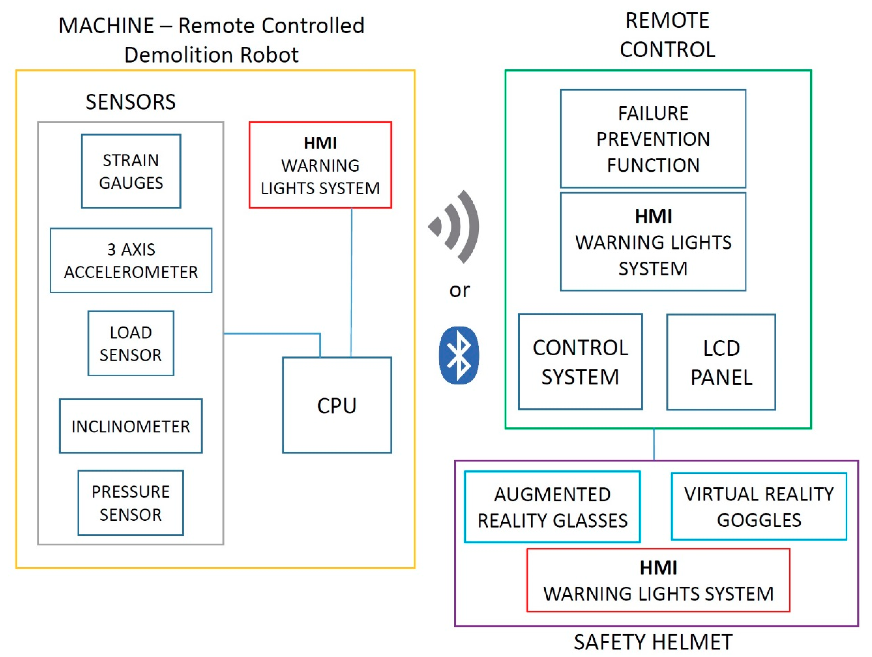
Figure 12 presents a block diagram of the proposed accident prevention system with all components based on the HMI.
The system is divided into two main units. The first unit is mounted on the machine and consists of a group of different sensors (strain gauges, accelerometers, inclinometer, and pressure sensors) and a previously designed arm-mounted HMI status/caution/warning lights system [
4] and the CPU. The second unit is located in the remote control (failure prevention function, HMI warning lights system connected to an LCD panel) and in the operator safety equipment (helmet, glasses, shield, ear protectors) which can be equipped with Augmented Reality glasses or Virtual Reality goggles and other HMI warning lights system. The HMI status/caution/warning lights can function as early warnings, which trigger when the machine is operating in a resonant frequency or exceeds the tilting angle α
C. For example, an alarm could go off and a red light could start blinking to notify the operator [
4], as depicted in
Figure 13.
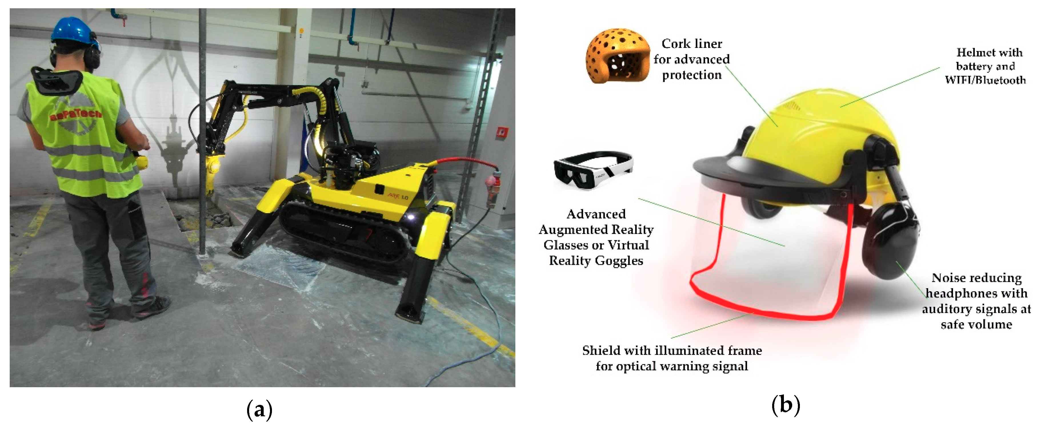
Considering the wide variety of applications of such demolition robots, there might be situations in which the visual HMI is ignored or unnoticed by the operator. In consequence, the information and notification about a hazard or misuse needs to be provided in close proximity to the operator, at least as an option for customers with different expectations concerning ergonomics and applicability. Therefore, the creation of a non-haptic feedback system could be an important improvement to the safety of the robot and the operator. The idea for this device is based on one important aspect of the operational system that all robots have in common: an operator with a helmet, safety goggles, and (circumaural) ear protection. Each of these elements is required by safety regulations for working environments and, as shown in
Figure 14a, performs many functions.
By offering additional functionalities, it would be possible to create a multi-part non-haptic feedback device with this safety equipment.
Figure 14b depicts a possible solution for an intelligent safety helmet with additional accident prevention features. Apart from adding systems described in the following paragraphs, the helmet can be filled with advanced light cork liner [
33,
34,
35] which reduces the energy upon impact.
The helmet protects the wearer mainly from head injuries resulting from falling or airborne items or from hitting static obstacles [
33,
34,
35]. Such a safety helmet is classified as personal safety gear by (national) safety regulations and is mandatory in most operational environments during deconstruction projects. Depending on the preferences of the company, the color of the helmet can also indicate the affiliation of a worker to a special department or that he or she is qualified to use special machinery, e.g., a demolition robot. Additionally, the safety helmet also serves, directly or indirectly, as storage for other components that the operator needs, e.g., safety goggles and ear protection. To supply these modified safety components with voltage and current, a battery and a Bluetooth/WIFI-device should also be installed, to enable communication between all components and reduce the hazard of injuries, such as strangulation by tethered components.
The second part of this essential safety gear are safety goggles which protect against eye injuries caused by dust, small particles, and airborne items as well as similar hazards to eyes in working environments described earlier. Safety goggles are also classified as personal safety gear and need to be worn in deconstruction projects such as house demolitions. An advanced system could be supplied by means of augmented reality glasses or Virtual Reality goggles which could provide the operator with additional data [
32,
36]. Since in warm and humid surroundings conventional goggles tend to become scratched and cause a foggy view, especially if the operator wears glasses, a shield could be used alternatively instead of goggles. A modification of the goggles or the shield consisting of a frame made of acrylic, or a similar light-conductor, illuminated by LED lights could serve as a visual warning system, e.g., by blinking, which is always visible and does not directly blind the operator or obstruct his or her view. The power source for this application lies in the battery stored inside the helmet.
Ear protection could serve as the third component in such a non-haptic feedback system [
31]. Its function is to prevent ear injury caused by high levels of noise and frequencies or airborne particles and items while working in a hazardous environment. Just as with the safety helmet and goggles, ear protection is classified as personal safety gear and needs to be worn when working in an environment where noise exceeds a given level. Since there is a foreseeable noise reduction by such ear protection, there are some advantages in the actual application of an acoustic warning signal in this component. By installing a headphone inside the ear protection, a warning signal could be emitted at a level that is deemed safe in relation to the noise level of the working environment. This is also convenient for the operator and makes the acoustic warning signal emitted by the remote control or the robot unnecessary, which also helps to reduce the noise of the working environment.
Additional features of the non-haptic feedback device, such as radio communication are also possible, but are not considered in this paper.
A combination of these technologies is recommended in designing tailor-made products that respond to specific expectations of end-users and are offered as a list of accessories and features. In this context, what is equally important is that applicability is not reducible to technical issues alone. It should be viewed in the context of technical requirements, its technical applications in the existing system, and, most importantly, the user’s approval.
Habits and suboptimal ergonomics in particular often lead to situations in which eye and ear protection are not worn or equipment is replaced by lighter, insufficiently-sized versions that affect the worker’s safety. Due to these practices and habits, the authors have decided to pursue a solution by combining the aforementioned features and techniques as a list of accessories in the next version of the demolition robot HMI.
5. Conclusions
The paper presents the use of a new design and construction method based on the study of user needs obtained through empathy research. The in-depth research combined with the analysis of the operational system helps to correctly identify the problem in operation of small machinery, which directly corresponds to the operator’s need. The proposed method allows the designer to explore the operational system and correlate the obtained data with user research. In order to increase workplace safety the study investigates the operation of heavy machinery, in particular remote-controlled demolition robots, in hazardous environments. The conducted user research and study of machines helped to identify the problem of accidents occurring during the operation of remote-controlled demolition machines (robots). The research also revealed that the machine does not provide feedback to the operator because of the untethered or uncoupled connection between them. By carrying out all processes in accordance with all stages of the proposed method, it was possible to develop a solution in the form of an HMI-based accident prevention system for machine operators.
There are two leading producers of demolition robots on the market, namely BROKK and Husqvarna [
37,
38]. An analysis of the range of robots that they manufacture indicates that no system exists to support the operator of a remote-controlled robot by providing the operator with feedback about the state of the machine, especially in dangerous situations [
37,
38].
This paper examines the potential visual feedback features of an HMI system that could increase the interaction between the machine and its operator and could serve as an upgrade of a previously designed arm-mounted early warning system [
4]. To create a fully integrated HMI system it is important to collect data by means of a vibrometer and a high-speed camera in all possible scenarios of machine operation.
In particular, the article shows that HMI is more than a one-way flow of information, which merely warns the operator about a potential hazard or breakdown [
27]. By implementing direct feedback devices, the warning system can directly counteract the decisions of the operator by intercepting the input commands and changing or limiting the operating parameters.
The results of experimental tests indicate the improper usage of machines and possible breakdowns of their mechanical structure. The combination of physical tests and additional FEM calculations [
23] can provide data that could help to fine-tune the configuration of the proposed accident prevention system.
Through its automated control functions the proposed warning and feedback has an increased capacity to interact with the operation of a remote-controlled machine in order to protect it against hazards and failures resulting from careless or improper operation by inadequately trained operators. Moreover, the system provides the user with feedback information about the robot’s performance, which allows the operator to use it properly and in the most optimal manner. Finally, the application of experimentally collected data in the designing process that includes all stages of the proposed method can contribute to the development of new functionalities or structural features that improve the entire machine.


