Article

Analysis of a Vibrating Motor Considering Electrical, Magnetic, and Mechanical Coupling Effect

School of Mechanical Engineering, Pusan National University, Busan 609-735, Korea
*
Author to whom correspondence should be addressed.
Appl. Sci. 2019, 9(7), 1434; https://doi.org/10.3390/app9071434
Submission received: 25 February 2019 / Revised: 29 March 2019 / Accepted: 1 April 2019 / Published: 5 April 2019
(This article belongs to the Section Mechanical Engineering)

Abstract

:
A vibrating motor is a multi-physics product in which there is coupling between electrical, magnetic, and mechanical domains. To obtain a more accurate analysis, nonlinear parameters, such as inductance, speedance, and force factor, are considered as functions of current and displacement based on the finite element method. By solving a voltage equation using a numerical iteration method, current and displacement at each frequency of the vibrating motor can be calculated. The validity of the analysis method was demonstrated by comparing the results of the experiment with those of the simulation and they were found to be similar.

1. Introduction

Electronic devices have fascinated people all over the world, with emphasis being placed on improving performance. Especially in the case of vibrating machines, such as vibrating motors, the importance of analyzing the electromagnetic and mechanical systems is becoming increasingly significant. To enable improvement, an accurate method of analyzing a motor is required and there are various suggestions available for motor analysis.
In previous studies, a novel design of a vibrating machine was analyzed using the finite element method (FEM) for the electromagnetic and mechanical fields [1,2,3,4]. A novel linear impact-resonant actuator was analyzed using a magnetic circuit model, which represented the magnetic circuit using a lumped parameter method [5]. Nam et al. proposed a novel design of a linear actuator with a large magnetic force to reduce the response time, which was analyzed by a transient analysis in the mechanical domain [6]. A resonant piezoelectric vibrator was developed and analyzed by outlining the mechanics of the piezoelectric unimorph [7,8].
There are several widely used approaches to conduct a multi-physics analysis, such as the equivalent circuit method (ECM), the lumped parameter method (LPM), and the finite element method. A new linear-electromagnetic actuator used for cellular phones was designed using the voltage equation of the equivalent circuit method that treated electromagnetic parameters such as inductance, speedance, and force factor as constant values [9]. A vibration actuator was developed based on active magnetic springs by taking advantage of polynomial fitting to outline the magnetic force characteristics [10], and Lee developed a horizontal linear vibrating actuator and modeled the mechanical domain by a two-degrees-of-freedom system that considered the electromagnetic and mechanical domains separately [11]. However, in both cases, nonlinear parameters such as inductance, speedance, and force factors were not considered. In other application fields, to make the electromagnetic-mechanical coupling analysis convenient, commercial software (COMSOL Multi-physics) has been developed. This software has been used to analyze a loudspeaker driver [12,13]. In the software, the mechanical forces are calculated as the product of a force factor and a current. The current is from the voltage equitation that considers the back electromotive force (EMF) term and both the current and displacement are calculated by the software.
In previous research, the characteristics of the electrical, magnetic, and mechanical coupling with respect to the inductance, speedance, and force factor, which are caused by the vibration of the motor, were considered as constant values. In this study, the nonlinear parameters are considered as functions of displacement and current to analyze the performance of the vibrating motor using FEM and a numerical iteration method. The electrical, magnetic, and mechanical coupling analysis considering nonlinear parameters of the vibrating motor is used for securing an accurate motor analysis result. A comparison between the ECM, commercial software, and the proposed method is given in Table 1.
The vibrating motor used in this research was cylindrical in shape and its outer diameter, height, direct current resistance (DCR), and input power were 10 mm, 4.1 mm, 12.6 Ω, and 1 W, respectively, as depicted in Figure 1.

2. Analysis Method

2.1. Electrical and Magnetic Analysis

During the electrical and magnetic analysis, the vibrating motor was modeled with several different positions of the vibrating part, and current was applied through the coil. The governing equations are Maxwell’s equations.
D = ρ B = 0 × H = J + D / t × E = B / t
where D is electric flux density, B is magnetic flux density, J is current density, H is permanent magnetic intensity, and ρ is the charge density.
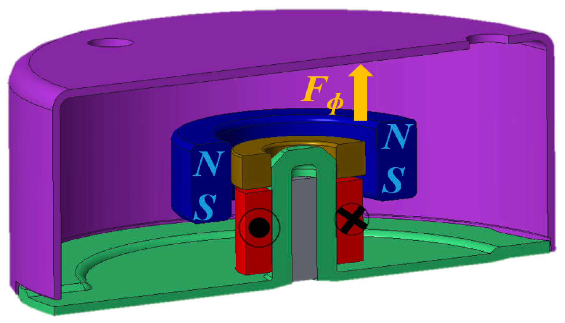
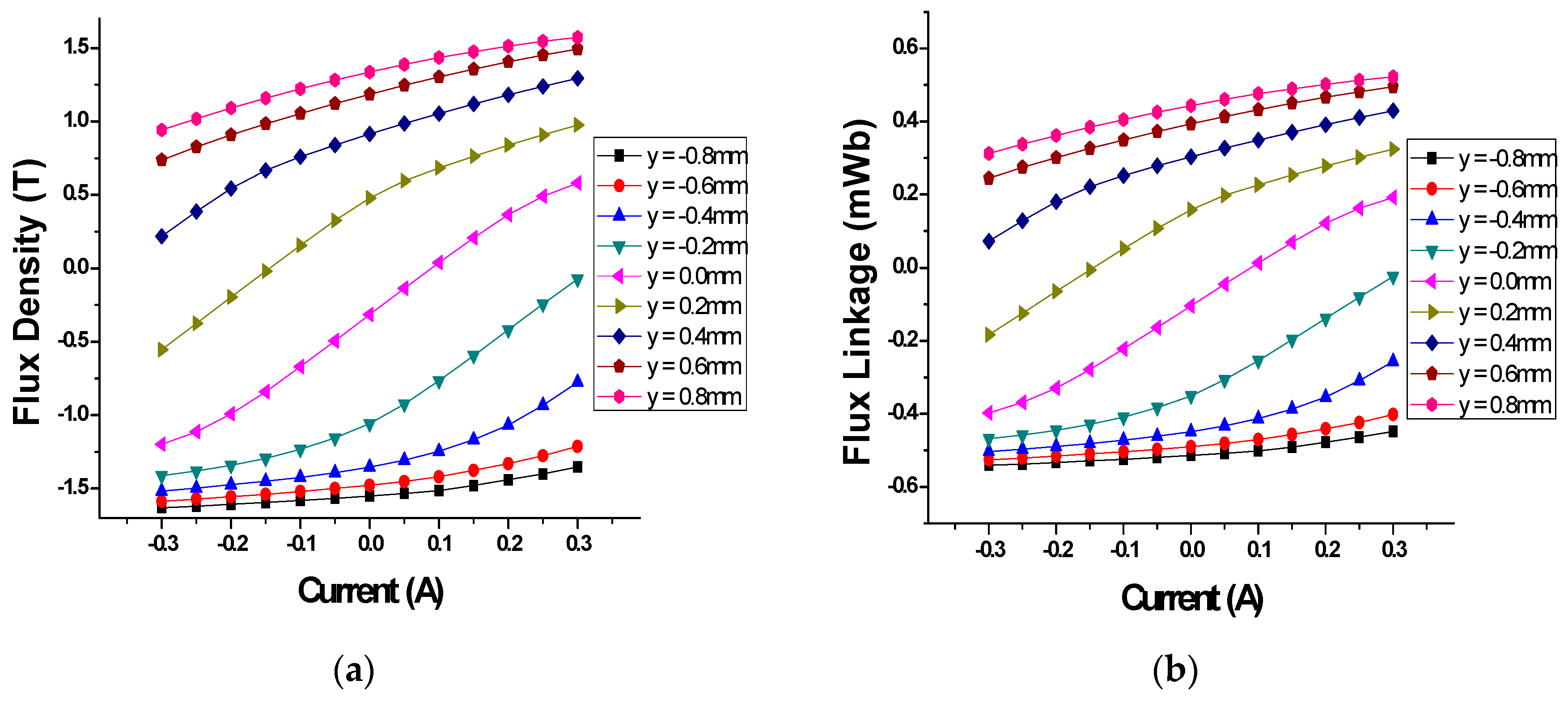
For each position and current, the flux density was obtained by FEM. After solving Maxwell’s equations, the flux density located at every node point in the model was acquired. The model used for electrical and magnetic analysis is shown in Figure 2.
After obtaining the results, the flux density was converted into flux linkage, from which it is easy to calculate the inductance and speedance.
The definition of flux linkage is the product of the flux density, coil turns, and the coil’s sectional area. The flux density and flux linkage are shown in Figure 3.
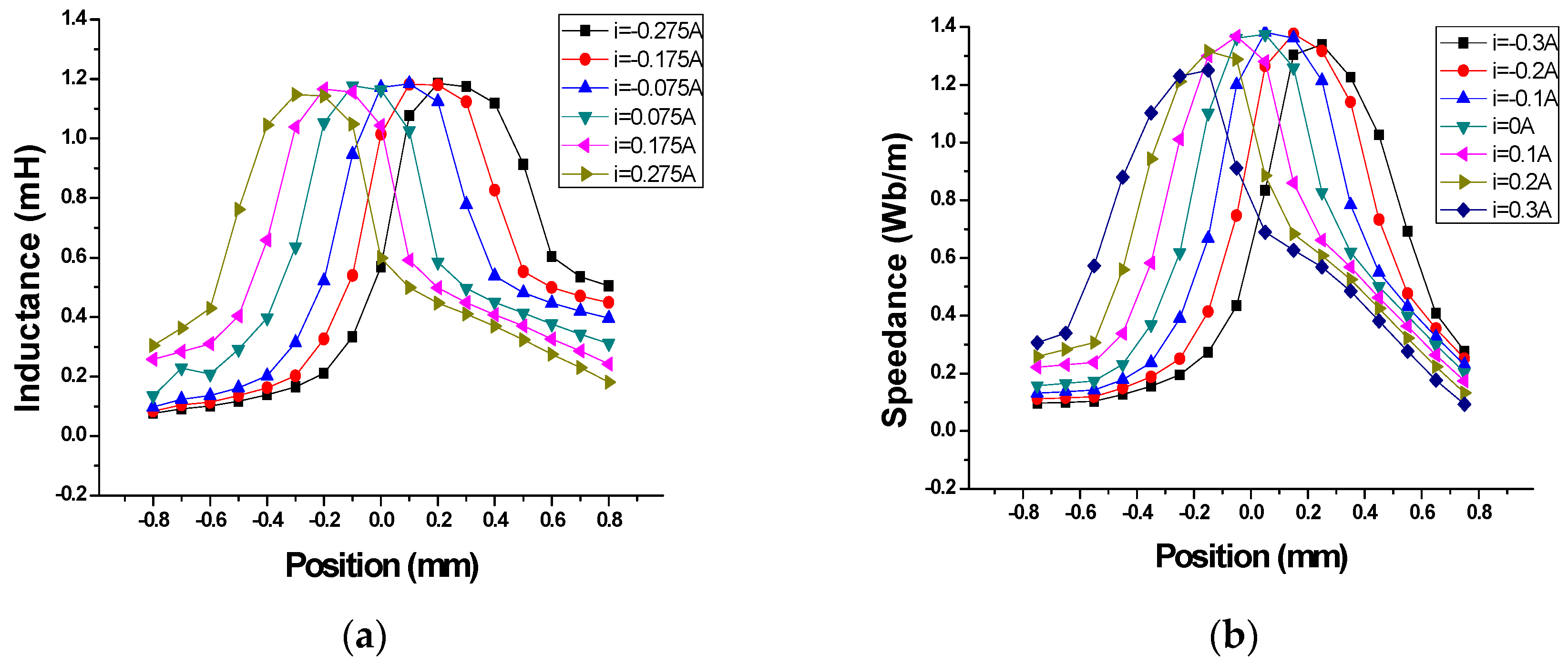
After calculating the flux linkage, inductance and speedance can be calculated using the following method: Inductance is defined as the derivative of flux linkage with respect to the current, and speedance is defined as the derivative of flux linkage with respect to displacement.
Additionally, flux linkage, inductance, and speedance are all functions of displacement and current and these parameters can be used to calculate the back EMF.
λ ( y , i ) = N S B ¯ x ( y , i ) L ( y , i ) = Δ λ ( y , i ) Δ i K e m f ( y , i ) = Δ λ ( y , i ) Δ y
where i, y, N, S, and Bx are current, displacement, coil turns, coil sectional areas, and average flux density, respectively.
λ(y,i), L(y,i), and Kemf(y,i) are flux linkage, inductance, and speedance, which are described as functions of displacement and current. By using flux density, the force that acts on the vibrating part was calculated using the Maxwell stress tensor method. The Maxwell stress tensor is a second-order tensor used in electromagnetic field analysis to represent the interaction between electromagnetic forces and mechanical momentum,
F m = 1 μ 0 S [ ( B n e ) B 1 2 B 2 n e ] d S
where Fm is the magnetic force, B is the flux density, ne is the unit normal vector, and S is the closed surface of the selected part. The electromagnetic force (Fm) is the force acting on the magnet of the motor and it is expressed as the total force (Ftotal). Because of the permanent magnet, magnetic material, and current, the total force (Ftotal) is composed of the cogging force (Fcogging) and the current force (Fcurrent).
The cogging force is a purely attractive force between the magnetic material and the permanent magnet depending on the position of the vibrating part when there is no current in the coil.
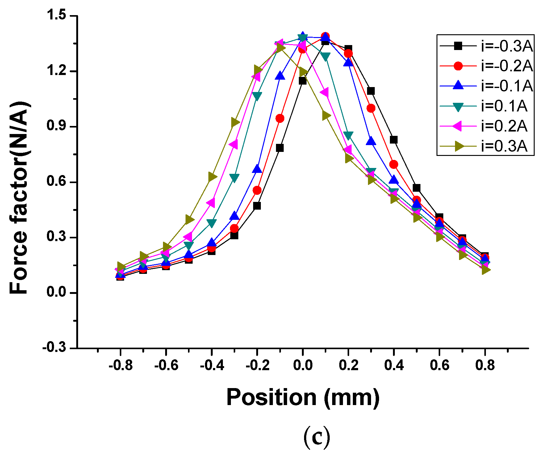
The current force is calculated by subtracting the cogging force from the total force on the vibrating part. Additionally, the force factor is calculated as the force divided by the current,
F c o g g i n g ( y ) = F t o t a l ( y , i ) | i = 0 F c u r r e n t ( y , i ) = F t o t a l ( y , i ) F c o g g i n g ( y ) K f ( y , i ) = F c u r r e n t ( y , i ) / i
where Fcogging(y), Ftotal(y,i), Fcurrent(y,i), and Kf(y,i) are the cogging force, current force, total force, and force factor, respectively. These parameters are also functions of current and displacement. The nonlinear parameters, such as inductance, speedance, and force factor, are expressed as functions of displacement and current, as shown in Figure 4.
The nonlinear parameters are constantly changing with position and current. These parameters are involved in the following voltage equation,
V = i R + L ( y , i ) d i d t + K e m f ( y , i ) d y d t
where V, R, and t are voltage, resistance, and time, respectively.

2.2. Mechanical Analysis

In the mechanical analysis, the displacement of the vibrating part was calculated using the FEM with forced vibration. The governing equation can be written as follows:
[ M ] y ¨ + [ C ] y ˙ + [ K ] y = { F c u r r e n t }
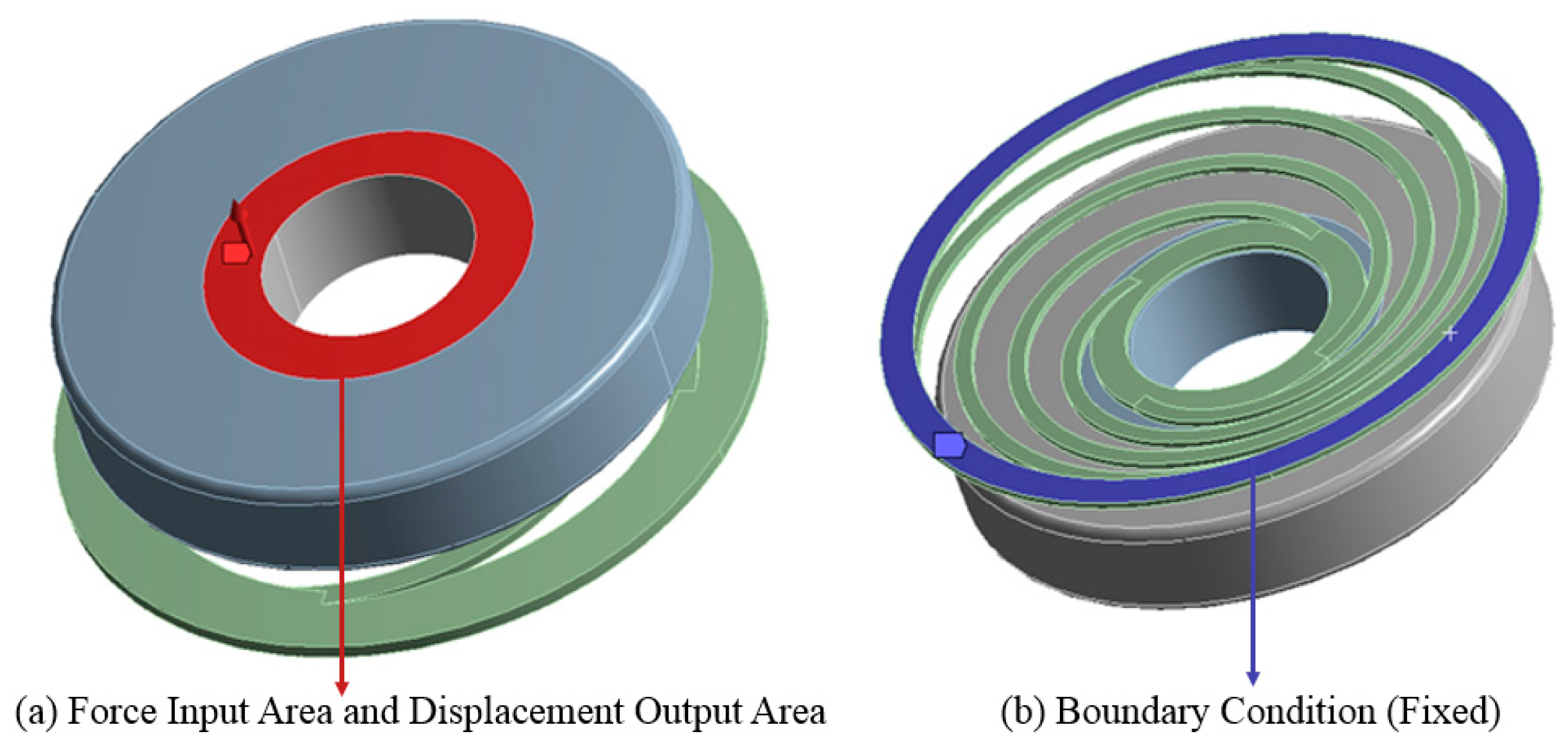
where [M], [C], [K], y, and {Fcurrent} indicate the matrix representations of mass, damping, stiffness, displacement, and the current force vector. The displacement of the vibrating part is obtained using a given input force and boundary condition for the vibrating motor. The model used for the mechanical simulation is shown in Figure 5.
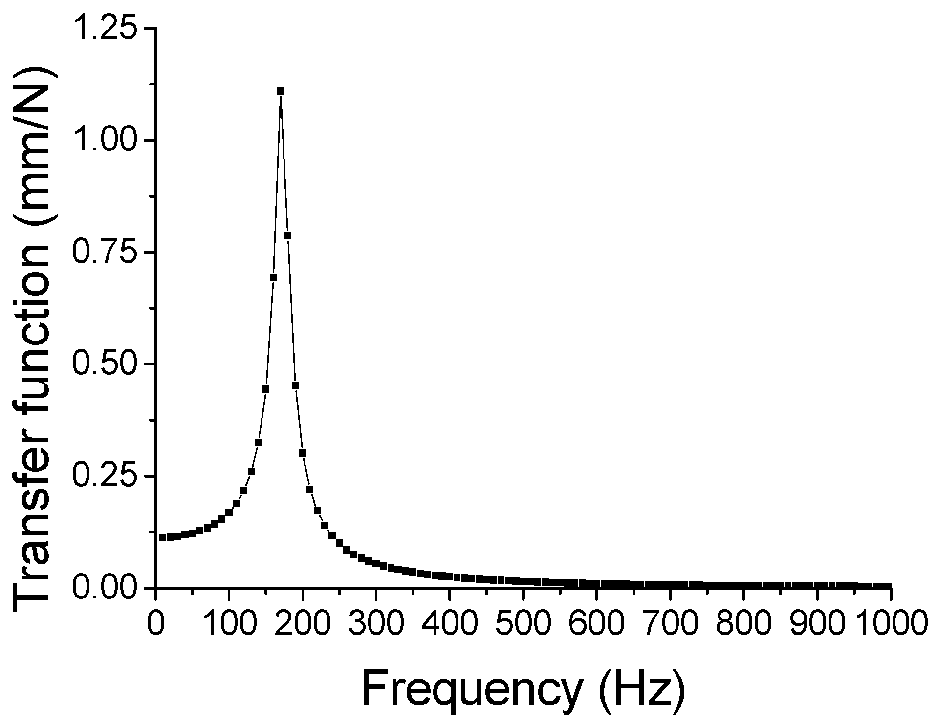
However, it is important to remember that the force applied in this step is a constant value. In reality, the force of the motor is constantly changing with current and position. Therefore, a transfer function is needed.
Because the mechanical system is linear, a transfer function can be applied between the input force and output displacement. The transfer function is defined as the output divided by the input of the system. The relationship can be described as follows:
h ( f ) = y 0 ( f ) f 0 = Y 0 ( f ) e i ( ω t + α ( f ) ) F 0 e i ω t = Y 0 ( f ) e i α ( f ) F 0
where h(f) is the transfer function that is shown in Figure 6, F0 is the assumed constant force amplitude, Y0(f) is the response displacement amplitude, and α(f) is the response displacement phase.

2.3. Electrical, Magnetic, and Mechanical Coupling Analysis

To perform the coupling analysis, two differential equations, which are the forced vibration equation and the voltage equation, must be solved simultaneously. However, it is difficult to solve these correlated equations by hand. Therefore, numerical analysis is needed to solve these two equations.
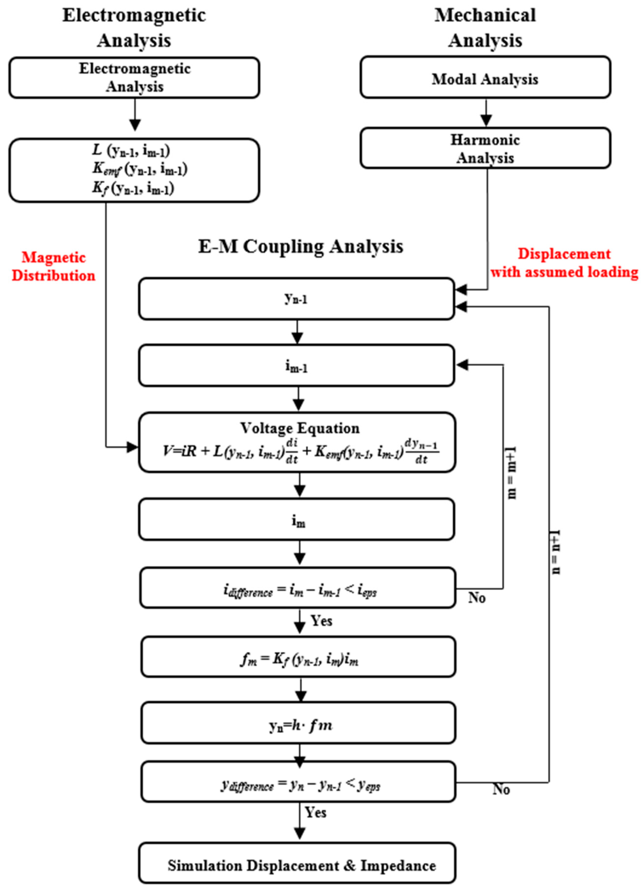
The numerical fixed-point iteration method was chosen to solve the electrical, magnetic, and mechanical coupling analysis. Figure 7 shows a flow chart that describes this method. The fixed-point method was chosen because it is easy to program in an application and the flow of the method can be seen and understood intuitively. Through this procedure, the forced vibration equation and the voltage equation can be solved simultaneously and the simulation displacement and current can be obtained. There are many other numerical methods that can be used to find the solution, such as the Newton–Raphson method or the modified secant method. These may provide the solution, but these methods require a more advanced level of programing skill.
In the electrical and magnetic analysis, the voltage equation is expressed with nonlinear parameters such as inductance, speedance, and force factor as Equation (5). Input voltage and current are waveforms and can be written using Euler’s formula. By dividing the input voltage into the input current, the impedance can be obtained as:
V I = Z e = R + j ω L ( y , i ) + j ω K e m f ( y , i ) y i
where y and i are the initial displacement and current and Ze is the impedance. Because the transfer function from Equation (7) is maintained, Equation (9) can be obtained:
y = f ( y , i ) h .
The actual force depending on current and displacement can be expressed as follows:
f ( y , i ) = K f ( y , i ) i .
By substituting Equations (9) and (10), Equation (11) can be obtained:
Z e = R + j ω L ( y , i ) + j ω K e m f ( y , i ) K f ( y , i ) h .
Here, the electrical, magnetic, and mechanical coupling effects are derived and, finally, the calculated impedance can be obtained using nonlinear parameters from the electrical and magnetic analysis and the transfer function from the mechanical analysis. By using this calculated impedance, the simulated current is obtained as follows:
i s i m u l a t e d = V Z e .
The simulated displacement and impedance can also be obtained:
y s i m u l a t e d = K f ( y , i ) h i s i m u l a t e d ,
Z e ,     s i m u l a t e d = V i s i m u l a t e d .
When using the numerical iteration method, the simulation was run until the initial values and simulated values converge. Before solving the voltage equation, the initial values of current and displacement, which are determined from the mechanical analysis, were set. For solving the voltage equation, the simulation procedure was as follows. In the beginning, frequency was given as an initial value, and the corresponding voltage and mechanical force were given. The initial values of current and displacement were fed into the simulation. By using the initial values, the initial impedance, which includes nonlinear parameters, was obtained. The value of the calculated current was acquired by dividing the voltage by the initial impedance. The calculated and initial current values were then checked to see whether they fall within the margin of error.
The simulation was run until the current converged. After the value of the calculated current was obtained, the displacement iteration, which includes current information, was started using the calculated current. Because of the electrical, magnetic, and mechanical coupling effects, both the current and displacement iterations should be considered at the same time. When the iteration was complete, the simulated impedance, current, and displacement were attained. Through the iterations, the current in the electrical and magnetic domains and the displacement in the mechanical domain were considered at the same time. At the beginning of the simulation, the initial values of current and displacement were assumed values. At the end of the simulation, the obtained values of current and displacement were very close to the experimental values.

3. Experiment

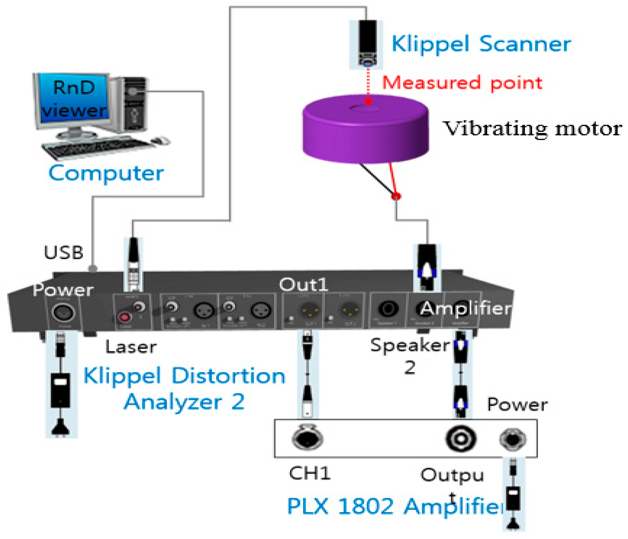
The displacement of the vibrating part of the motor was measured using Klippel equipment with a laser. By shooting the laser into the hole on the upper cover of the motor, the displacement of the vibrating part could be determined.
The method for measuring impedance was as follows. After applying voltage to the motor, the current, depending on the frequency, was measured by a current sensor in the Klippel equipment. By doing this, the impedance was calculated by dividing the measured current by the applied voltage.
The experiment setup of the Klippel equipment is shown in Figure 8, and the experimental conditions are demonstrated in Figure 9.
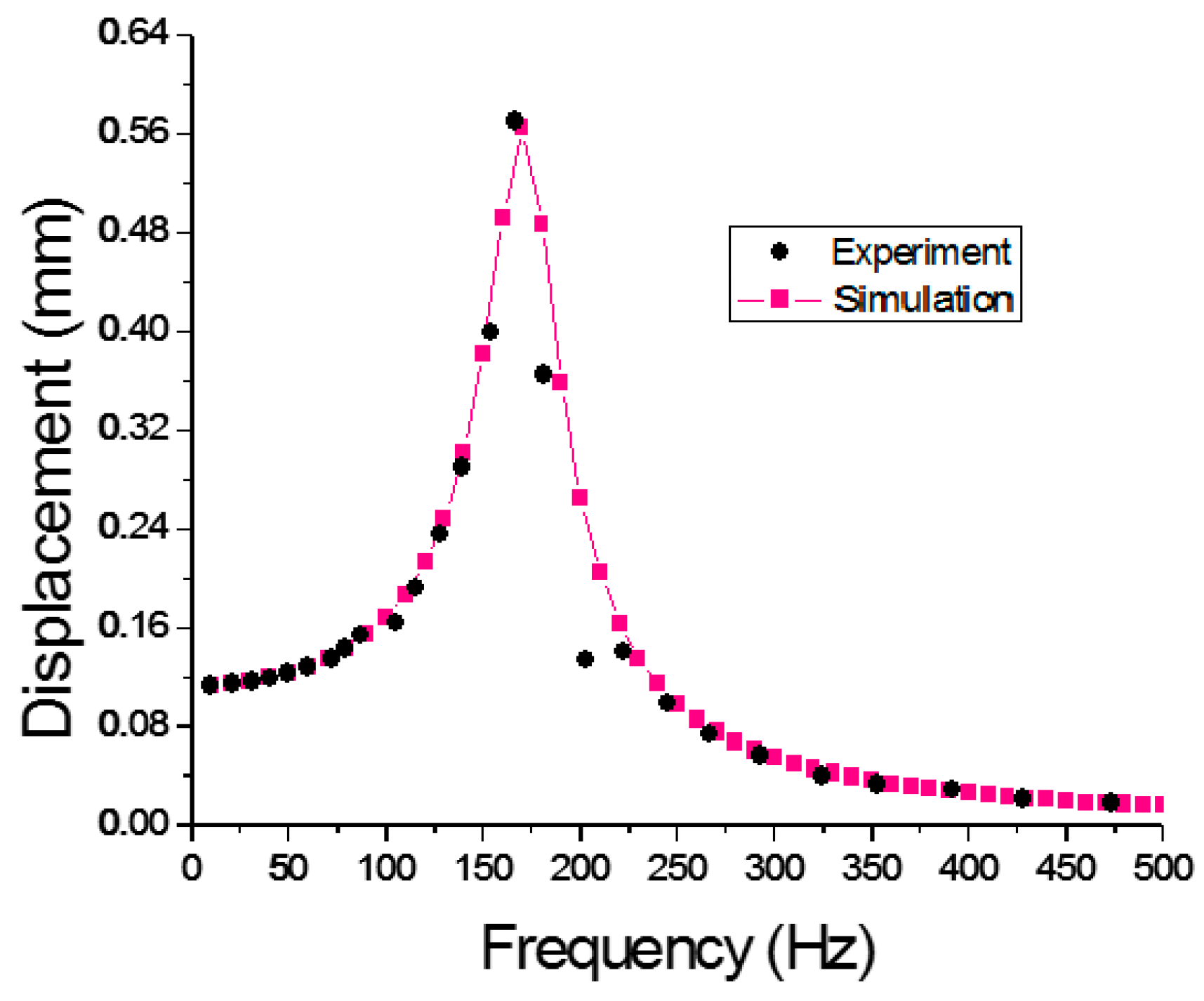
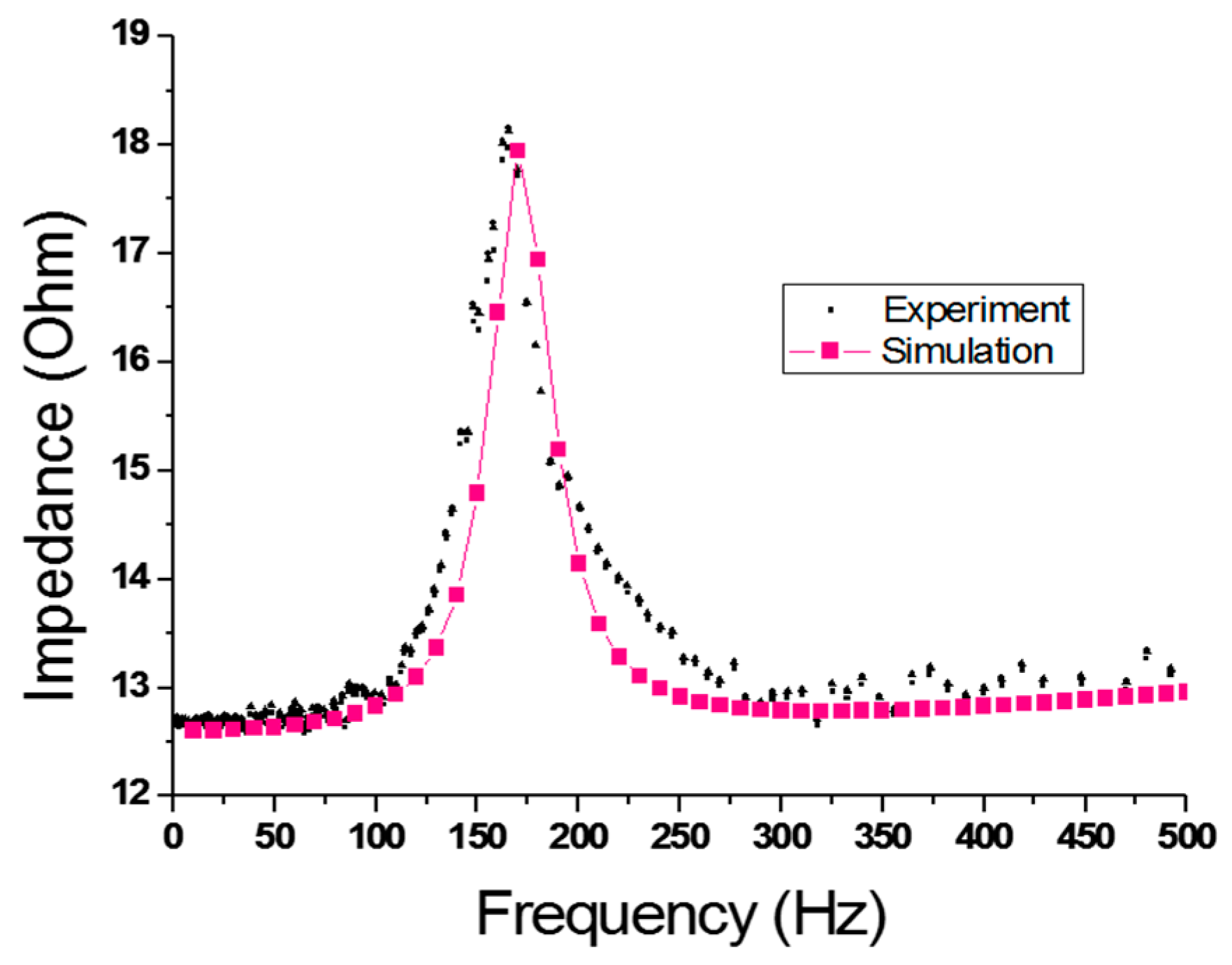
Finally, Figure 10 and Figure 11 show the simulated displacement and impedance compared with the experimental results obtained using the Klippel equipment. The results of the experiment and simulation match well.

4. Conclusions

A vibrating motor in electronic devices is influenced by electrical, magnetic, and mechanical coupling effects. In particular, the current and displacement of the vibrating motor are strongly affected by these characteristics because both have an influence on the nonlinear parameters, such as inductance and speedance. These two characteristics are closely linked and must be considered simultaneously.
In this work, an electrical, magnetic, and mechanical coupling analysis method is introduced by considering the nonlinear parameters, which are functions of displacement and current, based on a numerical iteration method combined with electrical, magnetic, and mechanical FEMs.
As part of the electrical, magnetic, and mechanical coupling analysis, the numerical iteration method was run to solve the voltage equation and obtain current and displacement values, which were found to be very close to experimental values. As the results of the simulation and experiment were almost identical, it is possible to say that the analytical method has been verified experimentally, as shown in Figure 10 and Figure 11.
In conclusion, this analysis method will be applied to the analysis of vibrating motor performance. Future work should be focused on designing a new type of vibrating motor with a more efficient and powerful performance.

Author Contributions

Conceptualization, J.-H.K. and Y.-W.J.; methodology, J.-H.K.; software, J.-H.K.; validation, J.-H.K.; formal analysis, J.-H.K.; investigation, J.-H.K.; resources, J.-H.K. and Y.-W.J.; data curation, J.-H.K.; writing—original draft preparation, J.-H.K.; writing—review and editing, J.-H.K., Y.-W.J. and S.-M.H.; visualization, J.-H.K.; supervision, S.-M.H.; project administration, S.-M.H.

Funding

This research received no external funding.

Conflicts of Interest

The authors declare no conflict of interest.

References

  1. Hwang, S.M.; Lee, H.J.; Chung, S.U.; Hwang, G.Y.; Kang, B.S. Development of solenoid-type vibrators used for mobile phones. IEEE Trans. Magn. 2003, 39, 3262–3264. [Google Scholar] [CrossRef]
  2. Park, J.H.; Sun, P.; Kwon, J.H.; Hwang, S.M. Optimal design of linear vibrators used in touch screen mobile phones. J. Mech. Sci. Technol. 2013, 27, 313–318. [Google Scholar] [CrossRef]
  3. Kim, J.H.; Park, I.O.; Oh, H.Y.; Choi, J.; Won, S.H. Development of the conical spring linear vibrator (CSLV) for mobile phone. In Proceedings of the 2005 IEEE International Magnetics Conference (INTERMAG), Nagoya, Japan, 4–8 April 2005; pp. 211–212. [Google Scholar]
  4. Wakiwaka, H.; Ezawa, M.; Kato, H.; Yoshimura, W.; Ito, H.; Fukuda, N.; Matsuhiro, K. Development of high-performance millimeter-size vibrator for cellular phones. J. Magn. Magn. Mater. 2002, 242, 1195–1197. [Google Scholar] [CrossRef]
  5. Pyo, D.; Yang, T.H.; Ryu, S.; Kwon, D.S. Novel linear impact-resonant actuator for mobile applications. Sens. Actuators A Phys. 2015, 233, 460–471. [Google Scholar] [CrossRef]
  6. Nam, J.; Yeon, T.; Jang, G. Development of a linear vibration motor with fast response time for mobile phones. Microsyst. Technol. 2014, 20, 1505–1510. [Google Scholar] [CrossRef]
  7. Nam, J.; Oh, H.; Jang, G. Externally leveraged resonant piezoelectric actuator with fast response time for smart devices. IEEE/ASME Trans. Mech. 2016, 21, 2764–2772. [Google Scholar] [CrossRef]
  8. Nam, J.; Kim, Y.; Jang, G. Resonant piezoelectric vibrator with high displacement at haptic frequency for smart devices. IEEE/ASME Trans. Mech. 2016, 21, 394–401. [Google Scholar] [CrossRef]
  9. Halmai, A.; Lukács, A. New linear-electromagnetic actuator used for cellular phones. Period. Polytech. Mech. Eng. 2007, 51, 19–22. [Google Scholar] [CrossRef]
  10. Olaru, R.; Arcire, A.; Petrescu, C.; Mihai, M.M.; Gîrtan, B. A novel vibration actuator based on active magnetic spring. Sens. Actuators A Phys. 2017, 264, 11–17. [Google Scholar] [CrossRef]
  11. Lee, K.B.; Kim, J.H.; Kim, J.H. 1108. Horizontal linear vibrating actuator to reduce smart phone thickness. J. Vibroeng. 2013, 15, 2003–2011. [Google Scholar]
  12. Hedges, M.J.D.; Lam, Y. Accuracy of fully coupled loudspeaker simulation using COMSOL. In Proceedings of the COMSOL Conference 2009, Milan, Italy, 14–16 October 2009. [Google Scholar]
  13. Salvatti, A. virtual acoustic prototyping—Practical applications for loudspeaker development. In Proceedings of the Audio Engineering Society Convention 129. Audio Engineering Society, San Francisco, CA, USA, 4–7 November 2010. [Google Scholar]
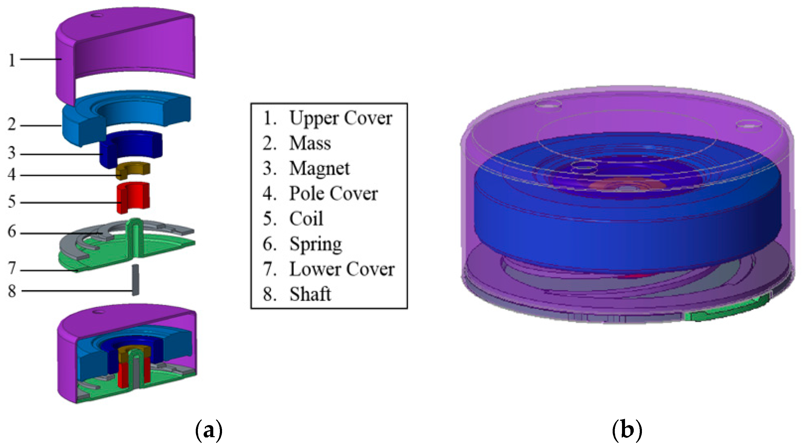
Figure 1. (a) Exploded view of vibrating motor. (b) Projection view of vibrating motor.
Applsci 09 01434 g001
Figure 2. Model used for electrical and magnetic simulation.
Applsci 09 01434 g002
Figure 3. (a) Flux density, (b) flux linkage.
Applsci 09 01434 g003
Figure 4. (a) Inductance; (b) speedance; (c) force factor.
Applsci 09 01434 g004aApplsci 09 01434 g004b
Figure 5. (a) Force input area and displacement output area; (b) boundary condition (fixed).
Applsci 09 01434 g005
Figure 6. Frequency-based transfer function.
Applsci 09 01434 g006
Figure 7. Flowchart of analysis procedures.
Applsci 09 01434 g007
Figure 8. Experimental equipment setup.
Applsci 09 01434 g008
Figure 9. Experimental conditions.
Applsci 09 01434 g009
Figure 10. Displacement comparison of experiment and simulation.
Applsci 09 01434 g010
Figure 11. Impedance comparison of experiment and simulation.
Applsci 09 01434 g011
Table 1. Comparison between the equivalent circuit method (ECM), commercial software, and the proposed method.
MethodStrengthWeakness
ECMFastNo consideration of nonlinear parameters
Commercial softwareEasy to useNo consideration of nonlinear parameters
Proposed methodConsideration of nonlinear parametersRequires complex post-processing