Abstract
Visible Light Positioning (VLP) is widely recognized as a cost-effective solution for indoor positioning with increasing demand. However, the nonlinearity and highly complex relationship between three-dimensional world coordinate and two-dimensional image coordinate hinders the good performance of image-sensor-based VLP. Therefore, there is a need to develop effective VLP algorithms to locate the positioning terminal using image sensor. Besides, due to the high computational cost of image processing, most existing VLP systems do not achieve satisfactory performance in terms of real-time ability and positioning accuracy, both of which are significant for the performance of indoor positioning system. In addition, the accurate identification of the ID information of each LED (LED-ID) is important for positioning, because if the LED-ID is not recognized well, the positioning can only be achieved in a particular positioning unit and cannot be applied to a large scene with many LEDs. Therefore, an effective image-sensor-based double-light positioning system is proposed in this paper to solve the above problems. We also set up relevant experiments to test the performance of the proposed system, which utilizes the rolling shutter mechanism of the Complementary Metal Oxide Semiconductor (CMOS) image sensor. Machine learning was used to identify the LED-ID for better results. Simulation results show that the proposed double-light positioning system could deliver satisfactory performance in terms of both the real-time ability and the accuracy of positioning. Moreover, the proposed double-light positioning algorithm has low complexity and takes the symmetry problem of angle into consideration, which has never been considered before. Experiments confirmed that the proposed double-light positioning system can provide an accuracy of 3.85 cm with an average computing time of 56.28 ms, making it a promising candidate for future indoor positioning applications.
1. Introduction
Due to the growing demand for accurate Location-Based Services (LBS), indoor positioning has been a hot research direction for the past few years. With the increase of large constructions, such as shopping malls and underground parking lots, the requirements for indoor positioning accuracy are getting higher and higher. Nevertheless, traditional indoor positioning systems such as WLAN, Zigbee, Ultra-Wideband (UWB), Bluetooth and Radio-frequency Identification (RFID) can only achieve tens of centimeters to a few meters of precision [1]. To meet the needs of high accuracy and instantaneity, a high-precision LED-based indoor positioning system using VLC technology is proposed. Visible light positioning (VLP) systems have the following advantages: First, multipath is more significant in VLP based on phase of arrival, however VLP based on angle of arrival or image sensors are more immune to multipath effects. Second, in some situations, such as hospitals and airplanes, VLC-based methods can still be used because LEDs do not generate radio frequency (RF) interference, and RF radiation is limited or even prohibited. Finally, as long as lighting infrastructures exist, VLC technology can be used to minimize hardware costs [2]. The indoor positioning method based on VLC can be divided into two categories: photodiode (PD)-based VLC [3,4] and image sensor-based VLC.
Since the direction of the light beam can affect PD to a large extent, the mobility of the positioning terminal is extremely limited. Another drawback of PD-based positioning is that a large error is usually generated due to the angular measurements, the measuring of received signal strength, varying intensities of light, and the solving of quadratic equations for position estimation jointly determining the result of the positioning [5]. In addition, it requires high-precision devices when it exploits phase difference of arrival (PDOA) or phase of arrival (POA), and time difference of arrival (TDOA) or time of arrival (TOA) to estimate the position of terminal [1]. Therefore, a promising alternative is using an image sensor as a receiver, which, according to the coordinates of LEDs in the real world and in the image, determines the location of the positioning. Unlike PD, we can use the image sensor not only in experimental conditions but also in practice without peripheral because of the combination of image sensor and commercial mobile phone. At the same time, it is immune to reflected light and generally able to provide a capture rate of 30 frames per second [6].
Thus far, there have been many image sensor-based VLC methods proposed, but few of them are practically available due to the lack of consideration for the actual scene and there is no preparation for high-speed indoor positioning in practical applications. For example, in [7], an additional six-axis sensor is used to determine the direction of the receiver and its position. This scheme uses collinearity condition to relate the 3-D coordinates of the LEDs to the 2-D coordinates of the image sensor. Simulation results show that the position of the receiver can be accurately estimated within 1.5 m if the pixel size is m. In [8], the 3-D coordinate information is transmitted by at least three LEDs from the LED lighting array. The 2-D image sensor receives the spatially separated lights by a lens and demodulates the 3-D coordinate information of each LED. Then, by solving two sets of quadratic equations that may lead to calculation errors, the position of the receiver is calculated. Analysis of those works shows that the accurate angle measurement and the solution of the quadratic equation for position estimation may lead to the positioning error of the original scheme. In [9,10,11], two image sensors near the unknown position receive and demodulate the 3-D coordinate information transmitted by at least four LEDs from an LED array. Then, from the geometric relations of the LED images that are created on the image sensor plane, the unknown position is calculated using a combination of vector estimation methods and least-square with the accuracy of decimeter level. Under the assumption that the image center is at the center of the pixel, this method does not require angular measurement. In practice, however, the center of the LED image rarely appears at the center of the pixel, so quantization errors are unavoidable. In addition, the separation between image sensors will largely determine the accuracy of positioning. Meanwhile, because of the existence of two image sensors, the complexity and quantization error of the two image sensors are at a high level. Therefore, in Luxapose [12], an AOA localization algorithm based on three or more LEDs is proposed, where a camera is regarded as an angle-of-arrival sensor.
In [13], the authors put forward an indoor positioning algorithm using at least three LEDs, which realized an accuracy of 0.001 m in simulation. However, there are certain limitations: (i) The FOV of most smartphone cameras is very limited. As for 3-D positioning, with the increase of Rx’s position, it would fail to position when there are fewer than three LEDs in the view. (ii) LED signal may be blocked by some objects such as walls and furniture in indoor environment, which causes the failure of positioning because the obstacles can lead to a situation where there are fewer than three LEDs in the visual of image sensor, as in the former case. Positioning may be interrupted or fail if fewer than three LEDs occur in the FOV of the camera, which greatly reduces the robustness and flexibility of the system. To reduce the number of required LEDs, in [14], the authors used two LED luminaires and an image sensor of camera as a receiver to realize the positioning accuracy of several cm in 3-D system. However, when only one LED is captured, the positioning fails. In [15], the authors adopted the localization algorithm from [14], and, if only one LED luminaire is captured, the position of the receiver would be simply located at the position of corresponding LED luminaires. In other words, it is just proximity. Hence, it causes great error of at least 82.5 cm in the 2-D positioning system of Reference [15] and the authors could not handle the situation where only one LED luminaire is captured. Meanwhile, the positioning algorithm of References [14,15] seems to be collinear, but they are only adapted to the occasion such as corridor with straight line distribution of LEDs instead of indoor environment with four square lamps. Besides, the authors did not demonstrate their positioning method based on two LEDs, let alone how they obtained the coordinate of Rx. Their work also left some unresolved issues for follow-up research. Meanwhile, the authors of [14,15] did not take the symmetry problem of angle into consideration.
Employing angular sensors is another straightforward way to measure the receiver’s orientation information, thereby “compensating” for the missing information caused by the reduced number of LED lamps. In [16,17], the authors provided single LED based localization by employing angular sensors or gyro. However, the use of angle sensors poses another problem. Previous studies have shown that a major source of positioning and navigation errors is inaccuracy of azimuth angles or measurement by magnetometers and gyroscopes [18]. In [19,20], the authors provided the techniques for position of the collinearity condition using single camera and LED street lights. In [19], the authors used the direct linear transformation and single value decomposition to solve the equation system for positioning. However, the robustness of the system is poor, and the algorithms are complicated where the scene is not collinear. In [20], the camera receives the visual information while the photodiode receives the visible light information, and the error of 3-D positioning is controlled at the decimeter level. In [21], a single LED positioning system based on circle projection using single image sensor is proposed and demonstrated. The LED image is no longer treated as a point in the actual scene, and the expressions for determining the orientation and position of the receiver are derived from the geometric parameters of the LED circle projection in the image. However, this method can only apply in a very short scope. According to our experiment, when the perpendicular distance between camera and LED increases (especially in a large indoor environment), the LED image on the image sensor plane can only be seen as a point. Otherwise, the geometric parameters of the LED circle projection will deliver a large percentage of error and cause a larger error in the positioning. Moreover, the marginal marker point mentioned in the paper can only be applied in a short range. Once the distance increases, it would be difficult to recognize and lead to a large error. Moreover, the algorithm in [21] is not suitable for practical application because of its complexity and large amount of computation. Finally, all above-mentioned studies (except Reference [15]) do not pay much attention to real-time ability, but only focus on static positioning and the positioning accuracy. However, both accuracy and real-time ability are crucial for indoor positioning systems.
The contribution of our work can be listed as follows. In this paper, firstly we propose an image-sensor-based double-light positioning system and set up relevant experiments to test the performance of the proposed system. Although the authors of [14,15] used a double-light positioning algorithm, the work in [14] does not consider the LED-ID recognition problem. If the LED-ID recognition is unsuccessful, the positioning would fail. In [15], there is a LED-ID recognition defect. If the LED-ID recognition is deviated, the positioning algorithm is difficult to exert a normal effect. This paper considers the problem of LED-ID recognition. Under the premise of accurate identification of LED-ID, the double-light positioning algorithm is used for accurate positioning. Accurate LED-ID recognition is the basis for the success of the positioning algorithm. If the LED-ID is not recognized correctly, the positioning would fail and the positioning algorithm would be meaningless. Secondly, we utilize the rolling shutter mechanism of the CMOS image sensor and combine machine learning algorithm to identify the LED-ID. Thirdly, in the proposed double-light positioning algorithm with low complexity, we take the symmetry problem of angle into consideration, which has not been considered before. Finally, the proposed double-light positioning system delivers satisfactory performance in terms of the real-time ability and the accuracy of positioning, and experimental results show that the proposed system could achieve an accuracy of 3.85 cm with an average computing time of 56.28 ms. The rest of the paper is organized as follows. Section 2 presents system principle and the double-light positioning algorithm. Section 3 shows the experiments and results of the proposed system. Section 4 provides concluding remarks.
2. System Principle
2.1. The LED-ID Detection and Recognition
The VLP system is mainly comprised of two processes: LED-ID recognition and the positioning algorithm. The recognition of LED-ID is realized by using the image sensor-based VLP, which utilizes the rolling shutter mechanism of the CMOS image sensor. The working principle of CMOS sensors and Charge Coupled Devices (CCD) sensor are shown in Figure 1. With a CCD sensor in Figure 1a, all pixels on the sensor are simultaneously exposed, thus, at the end of each exposure, the data of all pixels are simultaneously read out. This mechanism is often referred to as the global shutter of a CCD sensor. However, CMOS has a completely different working mechanism than CCD sensor. For a CMOS sensor, the data of this row are immediately read out whenever the exposure of one row is completed, which means that the exposure and data reading are performed row by row. This working mechanism is called the rolling shutter mechanism of the CMOS sensor. The image captured by the CMOS sensor would produce bright and dark stripes while turning the LED on and off during a period of exposure due to the rolling shutter mechanism of CMOS sensor [6,22].
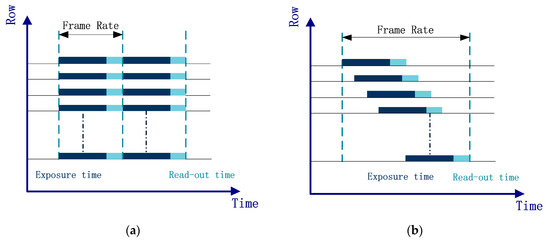
Figure 1.
Schematic diagrams of the: (a) global shutter of the CCD sensor; and (b) rolling shutter of the CMOS sensor.
For the same LED project, the change in distance from the CMOS sensor does not affect the width of light and dark stripes, because the scanning frequency of the CMOS sensor is fixed. However, the area of the LED project on the CMOS sensor will decrease as the distance between the LED and the camera increases, and this will also result in a reduction in the number of light stripes and dark stripes. Therefore, the area of the LED project, the number of bright stripes and the duty-ratio of the bright stripe were selected as the features of each LED, and a classifier was used to identify different LEDs. Our method is different from the traditional modulation and demodulation method, which introduces the classification algorithm from the field of machine learning to solve the problem of LED-ID detection and recognition. We modulate each LED using a varying frequency and duty-ratio Pulse-Width Modulation (PWM) method to enable the LED-ID to overproduce three identifiable features: the area of the LED project on the CMOS sensor, the number of the bright stripes, and the ratio of the width of the light stripe to the width of the light stripe and the dark stripe (the duty-ratio of the bright stripe). To identify LED-IDs using features that would be extracted by the image processing method, we use the Fisher classifier and the linear support vector machine through off-line training for the classifiers and online recognition of LED-ID. Experiments show that the proposed scheme could improve both the speed and accuracy of LED-ID identification and make the system more robust. The detail process of LED-ID detection and recognition has been deeply discussed in our prior work [22] and it can be seen in Figure 2. For the readers that are interested in the LED-ID modulation and recognition, please refer to our previous reports.
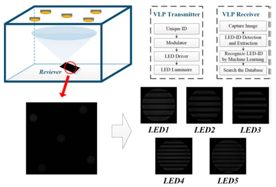
Figure 2.
The process of the LED-ID detection and recognition base on machine learning.
2.2. Double-Light Positioning Algorithm
Based on the above LED-ID image recognition, this section mainly introduces the double-light positioning algorithm in the positioning system. To the best of our knowledge, in the existing reports, only Jae-Yoon Kim et al. [14] realized VLC positioning on the base of two LEDs with one camera. However, unfortunately, the authors of [14] did not describe their proposed positioning scheme properly. Thus, we propose a new double-light positioning algorithm, as shown below:
The system model of the proposed double-light positioning algorithm is shown in Figure 3. The coordinates of LEDs are (x1, y1, z1), (x2, y2, z2) and, in general, the ceiling height is the same throughout, thus z1 = z2. Point P is the midpoint of the lens in the image sensor, which is estimated for the 3-D coordinate of the terminal. The distances from P to the LED anchors are for the two LED lamps. is calculated by the geometrical relationship between the focal length of the lens and the position of the LED pixel on the image sensor. Geometric relationship of the proposed double-light positioning scheme is detailed in Figure 3. The focal length of the lens is the intrinsic parameter of the camera. The distance between the center of the LED pixel and the center of the image sensors is for the two LED lamps. The pixel coordinate system and image coordinate system are both located on the imaging plane of image sensor, but they have different origin and different units of measurement. The relationship between the pixel coordinate system and image coordinate system is presented in Figure 4.
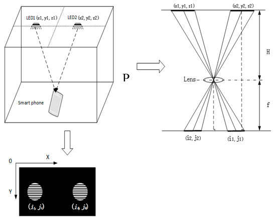
Figure 3.
Double-light positioning system model.
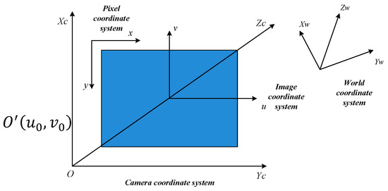
Figure 4.
(x, y) is the pixel coordinate system, (u, v) is the Image coordinate system, (Xc, Yc) is the Camera coordinate system and (Xw, Yw, Zw) is the world coordinate system.
The origin of image coordinate system is the point of intersection of camera’s optical axis and the image sensor imaging plane, i.e., the center of midpoint of the image sensor imaging plane. The unit of the mentioned image coordinate system is mm, which belongs to physical unit. The unit of the pixel coordinate is pixel, which is described by its row and line. Firstly, after obtaining the pixel coordinates of the two LEDs, according to the relationship between the pixel coordinate system and the image coordinate system, the coordinates of the two LEDs in the image coordinate system can be calculated:
Equations (1) and (2) can be rewritten in matrix form as:
where and represent the unit conversion of two coordinate system, i.e., 1 pixel = mm, , is the coordinate in the image coordinate system, , is the coordinate in the pixel coordinate system, and is the midpoint of image sensor’s imaging plane in pixel coordinate system. Therefore, we can obtain the conversion of the image coordinate system and the pixel coordinate system. Furthermore, we can get the distance between the midpoint of image sensor and the image of LED on the sensor :
The distance between the LED pixels is:
The physical distance between the two LEDs can be expressed as:
The vertical distance between the LED and the lens plane can be expressed as:
The Zc coordinate of the terminal can be located:
Zc = z1 − H = z2 − H
Thus, when the image coordinate system and the world coordinate system are parallel and have the same direction, the coordinate of the terminal in the camera system can be obtained according to the geometric relationship of similar triangles:
However, Equations (9) and (10) only present the relationship between the image coordinate and the world coordinate. If the image coordinate system and the world coordinate system are parallel and have the same direction, . However, under normal circumstances, there is no parallel relationship between the camera coordinate system and the world coordinate system. When the positioning image coordinate and the world coordinate system are not parallel, the results solved from Equations (9) and (10) cannot be used as the final result. Thus, a rotation angle , which is the angle between the world coordinate system and the camera coordinate system, should be introduced to solve the problem. Without loss of generality, as shown in Figure 5, we assume that the vector from the centroid of light source A to that of light source B is parallel to the axis . Thus, the vector from the projective point B’ to the projective point A’ is also parallel to axis , and the orientation of the receiver can be estimated by calculating the angle between the vector of B’A’ and the axis . Rotation angle of the positioning terminal can be obtained from a captured image of the LED lightings and it can be expressed as
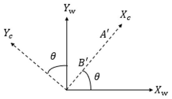
Figure 5.
The transformation model of camera coordinate system and the world coordinate system.
In our proposed algorithm, we put forward a method to find the true rotation angle by classified discussion. Figure 6 shows the different situations when the rotation angle change from 0 to 360° respectively, and is in a range of . In Figure 6a–e, are , respectively. Then, by rotating the image according to the obtained rotation angle, the image can be made parallel and equal to the coordinate axis. Therefore, we can rotate the coordinate by Equation (12) and realize positioning under any azimuth.
where (Xc, Yc, Zc) is the coordinate in the image sensor coordinate system and (Xw, Yw, Zw) is the coordinate in the world coordinate system.

Figure 6.
Different situations of the rotation angle : (a) the light and smartphone image sensor axes are the same; (b) the camera is rotated clockwise by ; (c) the camera is rotated counterclockwise by ; (d) the camera is rotated clockwise by ; (e) the camera is rotated counterclockwise by .
Although the authors of [16] proposed a positioning method based on two LEDs, they did not offer a specific positioning progress, which causes much confusion and suspicion. Meanwhile, we specifically explain how we determine the receiver’s position in the above introduction of our algorithm. Besides, they did not take the symmetry problem of angle into consideration, which we have explained. In another double-light positioning method mentioned in [16], confusion remains as to the process used. In addition, there are limitations of their method when the rotation angle is calculated because they did not take the symmetry problem of angle into consideration. Based on the above comparisons, we believe that our algorithm is superior to the previous methods.
3. Experiment and Analysis
We conducted experiments to verify the effectiveness of the proposed double-light positioning algorithm. As shown in Figure 7, there are five LEDs mounted on top of the frame. Since the proposed algorithm requires two LEDs, two of the LEDs are illuminated. Each LED luminaire is embedded with an 8-bit microcontroller unit (MCU) that encodes the unique identifier (UID) as a codeword that is not only suitable for optical transmission but also for flicker mitigation and dimming support. Using on–off keying intensity modulation (OOK IM), the LED driver can convert the codeword into modulated digital signals to drive the LED luminaire to emit the optical signals. We use the machine learning to detect and recognize LED-ID. Different from the traditional LED-ID encoding and decoding methods, we treat the LED-ID detection and recognition problem as a classification problem in machine learning filed. Once the LED image is captured by a CMOS image sensor, an image processing method is used to extract the features of LED-ID. To use the extracted features to identify the LED-ID, a Fisher classifier and a linear support vector machine are used. By off-line training for the classifiers and online recognition of LED-ID, the scheme proposed could improve the speed of LED-ID identification and improve the robustness of the system [22]. The drive circuit board is shown in Figure 8. Furthermore, we measured the time efficiency of our algorithm with the CMOS industrial camera (as the positioning terminal) and the computer Acer Aspire VN7-593G, Intel (R) Core (TM) i7-7700HQ CPU@ 2.8GHz, Ubuntu 16.04 LTS (as the software platform). Table 1 shows all important system parameters.
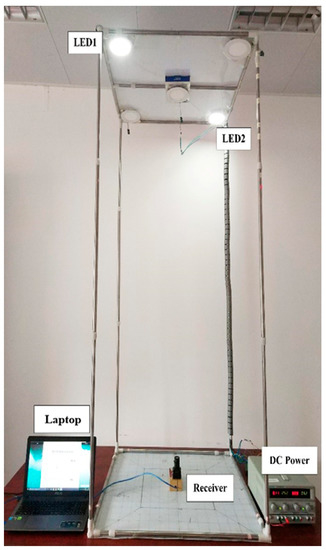
Figure 7.
The experimental platform of VLP system based on double-light positioning algorithm.
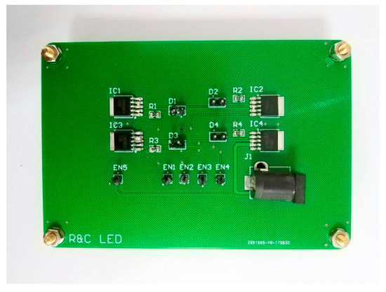
Figure 8.
The circuit board of transmitting terminal.

Table 1.
Parameter of the camera in this paper.
As shown in Figure 7, the performance of double-light algorithm was tested by an experiment, in which the coordinates (in cm) of the LEDs were (−33, −33, 200), (33, 33, 220). There were 16 evenly distributed test points at the height of 0 m, 0.1 m, 0.2 m and 0.3 m, respectively. Each position was tested six times, and the experiment tested a total of 384 positions. The positioning results are shown in Figure 9a–d, and Figure 9e–h shows the horizontal view of them.

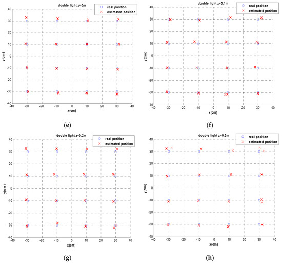
Figure 9.
The positioning results of double-light positioning system: (a–d) the 3-D positioning results at the height of 0 m, 0.1 m, 0.2 m and 0.3 m, respectively; and (e–h) the horizontal view of the 3-D positioning results at the height of 0 m, 0.1 m, 0.2 m and 0.3 m, respectively.
As shown in Figure 9, the estimated positions matched well with the real positions, which proved that the proposed double-light positioning algorithm could achieve high positioning accuracy. The spots in Figure 10 prove that, with different height of the camera, the positioning mean error barely changed. To better analyze the performance, Figure 11 gives the cumulative distribution function (CDF) of positioning error. CDF is defined as the probability that a random positioning error is less than or equal to the positioning accuracy. As observed in Figure 11, the CDF of over 90% of the positioning error was within 3 cm. The histogram of the errors in Figure 12 shows that the average error was about 1.99 cm, and all the positioning errors were within 3.85 cm. Therefore, it is obvious that the proposed double-light positioning algorithm could accomplish highly accurate positioning. Finally, the average positioning computing time of double-light positioning algorithm was 56.28 ms.
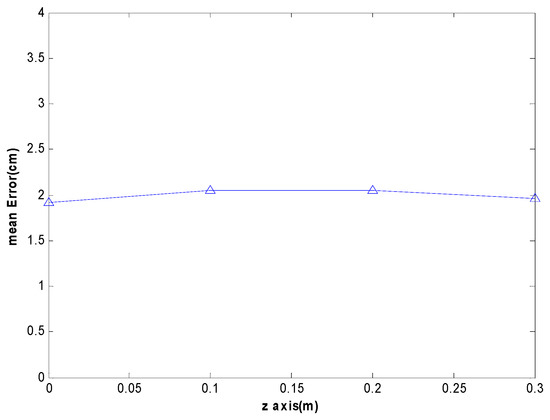
Figure 10.
The positioning error varies with height in double-light positioning system.
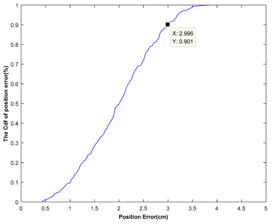
Figure 11.
The CDF curves of positioning error in double-light positioning system.
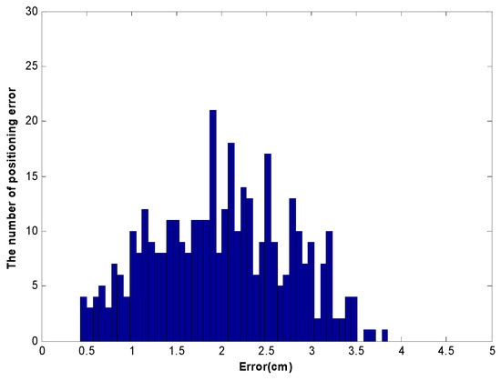
Figure 12.
Histogram of the triple-light positioning error in double-light positioning system.
Through the experiment above, it can be clearly seen that the proposed double-light positioning algorithm not only achieved a high positioning accuracy, but was also fully real-time capable. Compared with the methods in [16,17], as representative for the existing research on two LEDs in the VLP, the proposed double-light positioning algorithm had higher positioning accuracy (6.5 cm in [16] and 7.5 cm in [17]). Moreover, neither of the methods [16,17] takes the symmetry problem of angle into consideration. As for the positioning accuracy, the errors of the experiment were caused by the following reasons. First, some errors were caused by human measurement. The coordinates of the receiver position were determined by artificially drawing the grid, which easily caused the position coordinates of the receiver on the grid to deviate from the true position coordinates of the receiver. Second, the installation of LEDs and the placement of the camera could also cause some errors, i.e., the position of the luminaire had a certain coordinate deviation between the reality and the measured value. Finally, additional errors were generated by the algorithm itself. These errors in measurement, lamps installation, and camera placement were not available, but our algorithm ensured that good positioning accuracy could be achieved in the presence of these errors. In the case of considering all experimental errors, the positioning error was within 3.85 cm, indicating that the error of our algorithm was theoretically lower.
As for the real-time ability, most of the research on VLP only describes the positioning accuracy of their positioning algorithms, but does not express the real-time ability of their positioning algorithms. The proposed double-light positioning algorithm could realize positioning 17 times in 1 s, which represents good real-time performance. Moreover, the double-light positioning algorithm could be applied to robot positioning, as 17 positions in 1 s is sufficient.
4. Conclusions
This paper proposes a double-light positioning system based on image sensor and set up relevant experiments to test the performance of the proposed system. We utilize the rolling shutter mechanism of the CMOS image sensor and combine machine learning to identify the LED-ID. It is worth mentioning that the proposed double-light positioning system has satisfactory performance in real-time capability and positioning accuracy. In addition, the proposed double-light positioning algorithm has low complexity and takes the symmetry problem of angle into consideration, which is never not considered by other studies.
Compared with the existing work, the proposed double-light positioning algorithm is innovative and achieves high precision. A relevant experiment was conducted to demonstrate the positioning performance. Experiments showed that the proposed double-light positioning algorithm could provide an accuracy of 3.85 cm. Meanwhile, in terms of the real-time ability, the computational time of the proposed double-light positioning algorithm was reduced to 56.28 ms and could realize positioning 17 times in 1 s, which represents good real-time performance. Therefore, it can be concluded that the proposed double-light positioning algorithm delivers satisfactory performance in terms of real-time ability and positioning accuracy, which makes it a promising candidate for future indoor positioning applications.
Author Contributions
Conceptualization, W.G.; Data curation, X.Z. and J.L.; Formal analysis, X.Z. and J.L.; Investigation, X.Z. and Z.X.; Methodology, W.G.; Project administration, J.Z.; Resources, Y.W.; Software, J.Z. and X.Z.; Supervision, J.L.; Validation, W.G.; Visualization, J.Z.; Writing—original draft, W.G.; Writing—review & editing, W.G., X.Z. and Z.X.
Funding
This research was funded by National Undergraduate Innovative and Entrepreneurial Training Program grant numbers 201510561003, 201610561065, 201610561068, 201710561006, 201710561054, 201710561057, 201710561058, 201710561199, 201710561202, 201810561217, 201810561195, 201810561218, and 201810561219; Special Funds for the Cultivation of Guangdong College Students’ Scientific and Technological Innovation (“Climbing Program” Special Funds) grant numbers pdjh2017b0040 and pdjha0028; and Guangdong science and technology project grant number 2017B010114001.
Conflicts of Interest
The authors declare no conflict of interest.
References
- Guan, W.; Chen, X.; Huang, M.; Liu, Z.; Wu, Y.; Chen, Y. High-Speed Robust Dynamic Positioning and Tracking Method Based on Visual Visible Light Communication Using Optical Flow Detection and Bayesian Forecast. IEEE Photonics J. 2018, 10, 1–22. [Google Scholar] [CrossRef]
- Gu, W.; Zhang, W.; Kavehrad, M.; Feng, L. Three-dimensional light positioning algorithm with filtering techniques for indoor environments. Opt. Eng. 2014, 53, 107107. [Google Scholar] [CrossRef]
- Guan, W.; Wu, Y.; Wen, S.; Chen, H.; Yang, C.; Chen, Y.; Zhang, Z. A novel three-dimensional indoor positioning algorithm design based on visible light communication. Opt. Commun. 2017, 392, 282–293. [Google Scholar] [CrossRef]
- Guan, W.; Wu, Y.; Xie, C.; Chen, H.; Cai, Y.; Chen, Y. High-precision approach to localization scheme of visible light communication based on artificial neural networks and modified genetic algorithms. Opt. Eng. 2017, 56, 106103. [Google Scholar] [CrossRef]
- Guan, W.; Wen, S.; Liu, L.; Zhang, H. High-precision indoor positioning algorithm based on visible light communication using complementary metal–oxide–semiconductor image sensor. Opt. Eng. 2019, 58, 024101. [Google Scholar] [CrossRef]
- Guan, W.; Wu, Y.; Xie, C.; Fang, L.; Liu, X.; Chen, Y. Performance analysis and enhancement for visible light communication using CMOS sensors. Opt. Commun. 2018, 410, 531–545. [Google Scholar] [CrossRef]
- Yoshino, M.; Haruyama, S.; Nakagawa, M. High-accuracy positioning system using visible LED lights and image sensor. In Proceedings of the 2008 IEEE Radio and Wireless Symposium (RWS), Orlando, FL, USA, 22–24 January 2008; pp. 439–442. [Google Scholar]
- Horikawa, S.; Komine, T.; Haruyama, S.; Nakagawa, M. Pervasive Visible Light Positioning System using White LED Lighting. IEICE Techn. Rep. Circuits Syst. 2004, 103, 93–99. [Google Scholar]
- Rahman, M.S.; Haque, M.M.; Kim, K.D. Indoor Positioning by LED Visible Light Communication and Image Sensors. Int. J. Electr. Comput. Eng. 2011, 1, 420–431. [Google Scholar] [CrossRef]
- Rahman, M.S.; Haque, M.M.; Kim, K.-D. High precision indoor positioning using lighting LED and image sensor. In Proceedings of the 14th International Conference on Computer and Information Technology (ICCIT 2011), Dhaka, Bangladesh, 22–24 December 2011; pp. 309–314. [Google Scholar]
- Rahman, M.S.; Kim, K.-D. Indoor location estimation using visible light communication and image sensors. Int. J. Smart Home 2013, 7, 99–114. [Google Scholar]
- Kuo, Y.-S.; Pannuto, P.; Hsiao, K.-J.; Dutta, P. Luxapose: Indoor positioning with mobile phones and visible light. In Proceedings of the Annual International Conference on Mobile Computing and Networking (MOBICOM), Maui, HI, USA, 7–11 September 2014; pp. 447–458. [Google Scholar]
- Hossen, M.S.; Park, Y.; Kim, K.-D. Performance improvement of indoor positioning using light-emitting diodes and an image sensor for light-emitting diode communication. Opt. Eng. 2015, 54, 045101. [Google Scholar] [CrossRef]
- Kim, J.-Y.; Yang, S.-H.; Son, Y.-H.; Han, S.-K. High-resolution indoor positioning using light emitting diode visible light and camera image sensor. IET Optoelectron. 2016, 10, 184–192. [Google Scholar] [CrossRef]
- Fang, J.; Yang, Z.; Long, S.; Wu, Z.; Zhao, X.; Liang, F.; Jiang, Z.L.; Chen, Z. High-speed indoor navigation system based on visible light and mobile phone. IEEE Photonics J. 2017, 9, 1–11. [Google Scholar] [CrossRef]
- Hou, Y.; Xiao, S.; Bi, M.; Xue, Y.; Pan, W.; Hu, W. Single LED Beacon-Based 3-D Indoor Positioning Using Off-the-Shelf Devices. IEEE Photonics J. 2016, 8, 1–11. [Google Scholar] [CrossRef]
- Huang, H.; Feng, L.; Ni, G.; Yang, A. Indoor imaging visible light positioning with sampled sparse light source and mobile device. Chin. Opt. Lett. 2016, 14, 090602. [Google Scholar] [CrossRef]
- Li, F.; Zhao, C.; Ding, G.; Gong, J.; Liu, C.; Zhao, F. A Reliable and accurate indoor localization method using phone inertial sensors. In Proceedings of the 2012 ACM Conference on Ubiquitous Computing (UbiComp’12), Pittsburgh, PA, USA, 5–8 September 2012; pp. 421–430. [Google Scholar]
- Do, T.-H.; Yoo, M. Visible light communication based vehicle positioning using a rolling shutter CMOS sensor. In Proceedings of the International Conference on Ubiquitous and Future Networks (ICUFN), Vienna, Austria, 5–8 July 2016; pp. 48–50. [Google Scholar]
- Wang, Y.; Gong, Y.; Shi, Z. Research on the Collinear Equation Model of Visual Positioning Based on Visible Light Communication. In Proceedings of the International Conference on Engineering Technology and Application (ICETA 2015), Nagoya, Japan, 10–12 November 2015; Volume 22. [Google Scholar]
- Zhang, R.; Zhong, W.D.; Kemao, Q.; Zhang, S. A Single LED Positioning System Based on Circle Projection. IEEE Photonics J. 2017, 9, 1–9. [Google Scholar] [CrossRef]
- Xie, C.; Guan, W.; Wu, Y.; Fang, L.; Cai, Y. The LED-ID Detection and Recognition Method based on Visible Light Positioning using Proximity Method. IEEE Photonics J. 2018, 10, 1–6. [Google Scholar] [CrossRef]
© 2019 by the authors. Licensee MDPI, Basel, Switzerland. This article is an open access article distributed under the terms and conditions of the Creative Commons Attribution (CC BY) license (http://creativecommons.org/licenses/by/4.0/).