Article

From Symmetry Breaking via Charge Migration to Symmetry Restoration in Electronic Ground and Excited States: Quantum Control on the Attosecond Time Scale

by
ChunMei Liu
1,
Jörn Manz
1,2,3,* and
Jean Christophe Tremblay
1,4
1
Freie Universität Berlin, Institut für Chemie und Biochemie, 14195 Berlin, Germany
2
State Key Laboratory of Quantum Optics and Quantum Optics Devices, Institute of Laser Spectroscopy, Shanxi University, Taiyuan 030006, China
3
Collaborative Innovation Center of Extreme Optics, Shanxi University, Taiyuan 030006, China
4
Laboratoire de Physique et Chimie Théoriques, CNRS-Université de Lorraine, UMR 7019, ICPM, 1 Bd Arago, 57070 Metz, France
*
Author to whom correspondence should be addressed.
Appl. Sci. 2019, 9(5), 953; https://doi.org/10.3390/app9050953
Submission received: 21 January 2019 / Revised: 22 February 2019 / Accepted: 28 February 2019 / Published: 6 March 2019
(This article belongs to the Special Issue Attosecond Science and Technology: Principles and Applications)

Abstract

:
This article starts with an introductory survey of previous work on breaking and restoring the electronic structure symmetry of atoms and molecules by means of two laser pulses. Accordingly, the first pulse breaks the symmetry of the system in its ground state with irreducible representation I R R E P g by exciting it to a superposition of the ground state and an excited state with different I R R E P e . The superposition state is non-stationary, representing charge migration with period T in the sub- to few femtosecond time domains. The second pulse stops charge migration and restores symmetry by de-exciting the superposition state back to the ground state. Here, we present a new strategy for symmetry restoration: The second laser pulse excites the superposition state to the excited state, which has the same symmetry as the ground state, but different I R R E P e . The success depends on perfect time delay between the laser pulses, with precision of few attoseconds. The new strategy is demonstrated by quantum dynamics simulation for an oriented model system, benzene.

1. Introduction

It is nowadays well established that a laser pulse can break the electronic structure symmetry of atoms or molecules (as in Refs. [1,2,3,4,5,6,7]), a process that it often followed by charge migration (as in Refs. [8,9,10,11,12,13,14,15,16,17,18]). Recently, we showed that one can employ a well-designed second laser pulse that restores the symmetry of the electronic structure after application of a first symmetry-breaking pulse [19,20,21]. In the molecular case, by “symmetry” we mean the molecular point group, e.g., D 6 h for benzene, or in general the group of all symmetry operations such as rotations, reflections, and inversions that map the initial electronic eigenfunction (or a set of degenerate eigenfunctions) on itself, with the characteristic phase factors that are called “characters”. The characters determine the irreducible representations (IRREP) for the given symmetry, e.g., benzene has I R R E P g = A 1 g and various other I R R E P e (e.g., E 1 u ) in the electronic ground and excited states, respectively. Symmetry breaking means that the first laser pulse distorts the electronic wave function such that it can no longer be assigned to the original symmetry group. For example, in the case of benzene, the distorted electronic wave function can no longer be assigned to D 6 h symmetry. Likewise, symmetry restoration means that the second pulse re-shapes the wave function such that it can be re-assigned to the original symmetry group, irrespective of any possible changes of the IRREP. For example, in the case of benzene, symmetry restoration of electronic structure means that the electronic wave function can be re-assigned to D 6 h symmetry.
For reference, we use the next paragraph of this Introduction to explain our previous approaches to electronic structure symmetry breaking and symmetry restoration. This long paragraph also serves to introduce some important terminology that is employed in the rest of the paper. The following paragraph points to some related previous work. The remaining paragraphs define the goal of this paper, namely to develop a new strategy for breaking and restoring electronic structure symmetry.
The previous approaches to breaking and restoring electronic structure symmetry by two laser pulses have been demonstrated for two model systems, the 87 R b atom [19] and the oriented benzene molecule [19,20,21]. To achieve this goal, we designed two laser pulses centered at t b < 0 and at t r = t b > 0 , respectively. The time delay t d = t r t b between the pulses was chosen sufficiently long, and their durations sufficiently short such that, at the “central” time t c = ( t b + t r ) / 2 = 0 , the systems evolve in quasi-field-free environment.
At the same time, t d must be chosen short enough such that effects of decoherence (e.g., due to nuclear motions [13,14,22]) are negligible. Specifically, the coherence time of benzene exceeds ten femtosecond [13,14]; we note in passing that this is significantly longer than for the benzene cation where it lasts for just a few femtoseconds [23]. This allows using the model of fixed nuclei to describe the laser induced electron dynamics. In our simulations, the nuclei of benzene were fixed at the global minimum structure of the electronic ground state with D 6 h symmetry, adapted from Refs. [17,24,25,26]. Initially, at time t i t b , the systems were in their highly symmetric electronic ground states, S 0 ( 3 ) and D 6 h for 87 R b and benzene, respectively. The first laser pulse then broke symmetry by partial population transfer from the ground state with initial irreducible representation I R R E P g ( = D ( 0 ) and A 1 g , respectively) to an excited state with different I R R E P e I R R E P g (specifically, I R R E P e = D ( 2 ) and E 1 u , respectively). This created a superposition of the electronic ground and excited states that cannot be assigned to any IRREP (e.g., neither to I R R E P g nor to I R R E P e ) of the original symmetry groups ( S 0 ( 3 ) and D 6 h , respectively), but only to one of their subgroups. For example, the electronic structure of the 87 R b atom in the superposition state was anisotropic [19], and the electronic wave function of the superposition state of benzene had C s [19,21] or C 2 v [20] symmetry, different from the initial isotropic S 0 ( 3 ) or D 6 h symmetries, respectively. Since the superposition state is not an eigenstate, it is of course non-stationary. Since the nuclear wave functions that are associated with the electronic ground and excited states overlap, the non-stationary superposition state represents charge migration in the applications of Refs. [19,20,21]. The period T = h / Δ E of charge migration depends on the energy gap Δ E = E e E g between the levels E g and E e of the electronic ground and excited states. Typical values of Δ E are in the domain of several eV. The periods T of charge migration are, therefore, in the time domain from sub-fs to several fs. Specifically, for our applications to 87 R b and benzene, T = 0.992 fs and 0.504 fs, respectively. The second laser pulse de-excited the superposition state back to the ground state [19,20]. Consequently, charge migration was stopped, and finally (at time t f = t i ) the systems were back to their initial symmetry groups—specifically, they were back to S 0 ( 3 ) and D 6 h , respectively. Moreover, the previous approaches [19,20] also re-establish the original I R R E P g ( = D ( 0 ) and A 1 g , respectively). Successful applications depended on two conditions: (i) The second laser pulse was designed as a circularly polarized copy [19], or as time-reversed linearly polarized copy [20] of the first pulse for symmetry breaking. By “copies” we imply that the two laser pulses must have the same, or time-reversed properties. For example, they have the same carrier frequencies ω b = ω r , the same maximum field strengths ϵ b = ϵ r and corresponding maximum intensities I b = 0.5 ε 0 c 0 ϵ b 2 = I r (where ε 0 and c 0 denote the permittivity and speed of light in vacuo), the same ( e.g., Gaussian) shape functions with the same parameters for the durations τ b = τ r , the same carrier envelope phases η b = η r (usually set equal to zero), etc. (ii) The time delay t d had to be chosen “perfectly” such that at the central time t c = 0 , the two components of the superposition states had the same or opposite phases. If this condition is not satisfied, i.e., if the second pulse is centered at t r = t r + t with time t added to the “perfect” time t r , then at the final time t f = t f + t , the systems are left in the asymmetric superposition state, with non-zero populations P g ( t f ) and P e ( t f ) = 1 P g ( t f ) of the two components for the ground and excited states. An important analytical result is [19,20]
P e ( t f ) = 4 P g ( t c ) P e ( t c ) 1 2 1 2 cos 2 π t T ,
where P g ( t c ) and P e ( t c ) are the populations of the ground and excited states at the central time, t c = 0 . Symmetry restoration in the ground state requires that P g ( t f ) = 1 and P e ( t f ) = 0 . Obviously, Condition (ii) is satisfied if and only if t = 0 or t = T , 2 T , 3 T , etc. In practice, one may allow small deviations from this ideal requirement, by the order of few percents of the period T. In the applications to 87 R b and benzene (where T = 0.992 fs and 0.504 fs, respectively, see above), Condition (ii) thus requires “perfect” time delays, with precision of a few attoseconds. In Ref. [19], we developed robust numerical techniques for quantum dynamics simulations that fulfill this condition, with applications to the two model systems. The experimental feasibility is also presented in Ref. [19], by means of high-contrast Ramsey interferometry of the 87 R b atom.
In retrospect, one can find rather early examples in the literature of works involving electronic structure symmetry breaking and restoration, in particular in early work on Ramsey fringes [27,28], but the authors did not discuss the phenomenon. A more recent example comes from high harmonic generation (HHG). According to Corkum’s “simple man’s three step mechanism” [29], an atom or a molecule in the electronic ground state is first ionized by an intensive ultrashort laser pulse. In the second step, the same laser pulse accelerates the electron that was ejected in the first step, first by driving it away and then back to the ion. In the third step, the electron re-collides with the ion in a highly excited electronic state that decays back to the electronic ground state by spontaneous emission of HHG, see, e.g., Refs. [29,30,31,32,33]. In retrospective, this correspond to a kind of spontaneous symmetry restoration, although it was never recognized as such. The example of HHG is rewarding because it shows that restoration of electronic structure symmetry can be exploited for useful application. Laser control of electronic symmetry may also be used for chemical reactions [34,35,36,37] and for charge migration [10,17]. The efficiency of electronic symmetry restoration in HHG is rather low, however, because the probabilities of re-collision and spontaneous emission in the third step are rather small. Here, we aim at designing laser pulses that achieve close to 100 % restoration of electronic structure symmetry. In a general perspective, the present development may thus be considered as contribution to quantum control [38,39,40].
The goal of this article is to develop a new strategy for restoration of electronic structure symmetry by means of the second laser pulse, after symmetry has been broken by a first pulse. For convenience, we employ the same mechanism of symmetry breaking by the first laser pulse as previously [19,20,21], namely by exciting the system from its electronic ground state to a superposition of the ground state and an excited state with I R R E P e different from I R R E P g . The purpose and the mechanism of the second laser pulse is, however, quite different from the previous de-excitation of the superposition state back to the ground state [19,20]: It excites the component of the ground state in the superposition state to the excited state, which means it prepares the excited state as a pure eigenstate with the same electronic symmetry as the original one. Its I R R E P e is, however, different from the original I R R E P g (e.g., in the case of benzene with symmetry D 6 h , the excited target state may have I R R E P e = E 1 u , which is different from I R R E P g = A 1 g ). A special case of this strategy is already presented in Ref. [21]. There, the discovery is motivated by Equation (1), which yields P e ( t f ) = 1 if P g ( t c ) = P e ( t c ) = 0.5 and t = T / 2 or 3 T / 2 , 5 T / 2 , etc. (Note that the work in Ref. [21] employs alternative definitions of time delays.) The requirement of equal populations P g ( t c ) = P e ( t c ) = 0.5 called for the special design of the first laser pulse as so-called π / 2 laser pulse [41]—in Ref. [21], this is a circularly polarized π / 2 pulse as in Ref. [11,17]. Our new theory removes this restriction, i.e., symmetry may be broken by arbitrary first laser pulses, and, in any case, the second laser pulse is tailored such that it restores electronic structure symmetry in the excited eigenstate with I R R E P e . The new approach was exemplified by quantum dynamic simulation for the oriented model benzene. We show that the new strategy requires different laser pulses for symmetry breaking and restoration, i.e., they are no longer (time-reversed) copies of each other, but they still require “perfect” time delays with attosecond precision.
Section 2 presents the model, the concept, the basic and extended theory and the methods. The results and discussions are in Section 3. The conclusions are in Section 4.

2. Model, Concept, Theory and Methods

This section is divided into three parts. In the first subsection, we introduce the model and present some general aspects of the theory, together with the necessary details of the theory for symmetry breaking by a laser pulse. This part mostly builds upon and is quite similar to the theory published in our previous work (see Section 1)—we call it the “basic” theory. It is included here for self-containment of this article. The second subsection describes the new strategy for breaking the symmetry of the electronic structure of the electronic ground state and for restoring it in an excited state with different I R R E P e I R R E P g . The third subsection presents the theory for the new strategy—we call it the “extended” theory.

2.1. Model and Basic Theory

Our model assumes that all nuclei are fixed at the global minimum structures of the molecules in the electronic ground state, as in the previous approaches (cf. Section 1). We consider the scenario of an oriented molecule with its center of mass at the origin of the laboratory frame. This frame has a right-handed Cartesian set of unit vectors e x , e y , e z which are determined by the laser pulses. For example, in the present application to benzene, the laser pulses propagate along e z with perpendicular circular polarizations that yield maximum field strength of the first laser pulse along e x at time t b . The benzene molecule is oriented in the x y -plane of the laboratory frame, with two carbon nuclei on the y-axis, as in Refs. [17,24,25,26]. The laser carrier frequencies ω b = 2 π ν b and ω r = 2 π ν r correspond to wavelengths λ b = c 0 / ν b and λ r = c 0 / ν r , respectively, that are much longer than the molecular sizes. In the molecular domain that is of interest here, the electric fields of the laser pulses be considered as homogeneous.
The model Hamiltonian of the molecule interacting with the laser pulses is
H ( t ) = H e d · ϵ ( t ) ,
where
H e = T e + V c
is the electronic Hamiltonian that accounts for the kinetic energies T e of the electrons and for their intramolecular Coulomb interactions V c with all particles (electrons and fixed nuclei). The scalar product d · ϵ ( t ) represents the semiclassical interaction of the electric dipole operator d and the electric field ϵ ( t ) of the two laser pulses that break and restore electronic structure symmetry.
The electronic eigenfunctions | Ψ k and their energies E k are calculated as solutions of the time-independent Schrödinger equation (TISE)
H e | Ψ k = E k | Ψ k .
The labels k denote sets of quantum numbers, which include the IRREPs. Specifically, k = g and k = e denote the electronic ground state ( I R R E P g ) and the specific excited state ( I R R E P e ) that constitute the superposition state which is prepared by the first laser pulse,
| Ψ ( t c ) = c g ( t c ) | Ψ g + c e ( t c ) | Ψ e
with coefficients c g ( t c ) and c e ( t c ) at the central time t c = 0 between the two laser pulses. The new strategy uses the second laser pulse to excite this superposition (Equation (5)) to the final state
| Ψ ( t f ) = e i η e f | Ψ e
with irrelevant phase factor e i η e f for the phase η e f η e ( t f ) of the excited state at t = t f . Preparation of the final state (Equation (6)) restores the original point group of the initial ( t = t i ) ground electronic state
| Ψ ( t i ) = | Ψ g .
The inherent two-state scenario that leads from the initial ground state (Equation (7)) via the superposition state (Equation (5)) to the excited target state (Equation (6)) is justified in the beginning of Section 2.3. The laser driven electronic wave function | Ψ ( t ) is calculated as solution of the time dependent Schrödinger equation (TDSE)
i t | Ψ ( t ) = H ( t ) | Ψ ( t )
subject to the initial condition in Equation (7). Expanding the wave function | Ψ ( t ) in terms of a finite set of the eigenfunctions
| Ψ ( t ) = k c k ( t ) | Ψ k
yields the algebraic version of the TDSE
i d d t c ( t ) = H ( t ) c ( t ) ,
with vector c ( t ) of the coefficients c k ( t ) and corresponding initial condition
c k ( t i ) = δ g k ,
where δ g k denotes the Kronecker delta. The coefficients are in general complex-valued; they can be written as
c k ( t ) = C k ( t ) e i η k ( t )
with real valued amplitudes C k ( t ) and phases η k ( t ) . The matrix elements of the Hamilton matrix H ( t ) are
H k l ( t ) = Ψ k | H ( t ) | Ψ l = E k δ k l d k l · ϵ ( t )
with k l transition dipole matrix element d k l = Ψ k | d | Ψ l . In the case of benzene, the diagonal matrix elements vanish, d k k = 0 , for symmetry reasons.
The absolute squares of the coefficients c k ( t ) yield the populations, or the probabilities of occupying the eigenstate labeled k in the superposition (Equation (9)) at time t,
P k ( t ) = | c k ( t ) | 2 = C k 2 ( t ) .
These probabilities are normalized,
k P k ( t ) = 1 .
In particular, the initial electronic ground state (Equation (7)) implies that P k ( t i ) = δ g k (cf. Equation (11)). The populations of the ground and excited states in the superposition (Equation (5)) at time t c after the first laser pulse are
P g ( t c ) = | c g ( t c ) | 2 , P e ( t c ) = | c e ( t c ) | 2 ,
whereas all other coefficients and probabilities are equal to zero at time t c . The normalization in Equation (15) implies that the coefficients at time t c can be parameterized as
c g ( t c ) = cos α · e i η g ( t c ) , c e ( t c ) = sin α · e i η e ( t c ) .
The final populations are
P k ( t f ) = δ e k
in accord with Equation (6).
The formal solution of the TDSE (Equation (10)) with the initial condition in Equation (11) is
c ( t ) = U ( t , t i ) c ( t i ) = T ^ e i t i t d t H ( t ) / c ( t i ) ,
where U ( t , t i ) is the matrix representation of the unitary operator for propagating the electronic wave function | Ψ ( t ) from the initial time t i to t, and T ^ is the time-ordering operator. In practice, the algebraic TDSE (Equation (10)) is propagated numerically, using the methods which have been developed in Ref. [19]. The coefficients at the central and final times, i.e., after the first and second laser pulses are thus
c ( t c ) = U ( t c , t i ) c ( t i ) ,
c ( t f ) = U ( t f , t i ) c ( t i ) = U r ( t f , t c ) U b ( t c , t i ) c ( t i ) .
In the second part of Equation (21), we have separated the evolution operator U ( t f , t i ) into two parts for symmetry breaking and restoration by the first and second laser pulses,
U ( t f , t i ) = U r ( t f , t c ) U b ( t c , t i )
where
U b ( t c , t i ) = U ( t c , t i )
and
U r ( t f , t c ) = T ^ e i t c t f d t H ( t ) / .
If the time delay between the two laser pulses is prolonged by additional time t for quasi-field-free evolution, as discussed for Equation (1), we obtain by using the Schrödinger picture
U ( t f , t i ) = U r ( t f , t ) U f ( t , t c ) U b ( t c , t i ) = U r ( t f , t c ) U f ( t , t c ) U b ( t c , t i )
where t f = t f + t , and U f ( t , t c ) is the propagator for the free evolution. It is diagonal, with matrix elements [19,20]
U f ( t , t c ) k l = e i E k t / δ k l .
In the second part of Equation (25), we exploit the fact that the effect of the second laser pulse with additional time delay t t c during the time-shifted period from t to t f is the same as the effect of the original second laser pulse without additional time delay during the period from t c to t f .
We close this subsection by stating some general results for the matrix representation of the evolution operator for symmetry breaking. The laser pulse for symmetry breaking transforms the initial state (Equation (7)) to the superposition (Equation (5)) of the ground (g) and excited (e) states. Let us list the molecular eigenstates in the order g , e , e , e ... The corresponding order of the coefficients is c ( t ) = ( c g ( t ) , c e ( t ) , c e ( t ) , c e ( t ) , ) . Then, U b ( t c , t i ) takes block diagonal form
U b ( t c , t i ) = U b g e ( t c , t i ) 0 0 U b n g e ( t c , t i )
where
U b g e ( t c , t i ) = cos α · e i η g ( t c ) sin α · e i η g ( t c ) sin α · e i η e ( t c ) cos α · e i η e ( t c )
is the 2 × 2 block matrix for propagating states g and e from initial time t i to t c , and U b n g e ( t c , t i ) is the block matrix for propagating all other (“non-ge”) states. The first column of U b g e ( t c , t i ) is imposed by Equation (17), while the second column is a consequence of the unitarity of U b g e ( t c , t i ) . The form of U b n g e ( t c , t i ) is irrelevant for the present application because the first laser pulse does not transfer population from the initial ground state to any other excited states e , e , at the central time t c .

2.2. Conceptual Background for the New Symmetry Restoration Strategy

After the first laser pulse has broken the symmetry of the initial electronic ground state (Equation (7)) by exciting it to the superposition state (Equation (5)), our new strategy suggests that the second laser pulse should restore symmetry by transferring the superposition state (Equation (5)) to the excited state (Equation (6)). The net result of the combined first and second laser pulses is thus to excite the ground state (Equation (7)) to the target state (Equation (6)). It is well known that complete population transfer can be achieved by a resonant π -pulse [41,42]. This suggests the concept which can be written symbolically as
first laser pulse + second laser pulse = resonant π pulse .
Equation (29) should be read as condition for the second laser pulse: It should be designed such that the sum of the two pulses is a resonant π -pulse. This condition holds irrespective of the polarizations of the laser pulses, i.e., they may be linearly x- or y-polarized, or circularly right (+) or left (−) polarized. The expressions for linearly [41] and circularly [42] polarized resonant π -pulses are similar. They all have in common that the x- and/or y-components of the electric field of the pulse that propagates along e z are written as amplitude ϵ 0 ( = the maximum field strength) times a shape function s ( t ) (where max s ( t ) = 1 ), times cosinusoidal or sinusoidal functions cos ω ( t t r e f ) + η C E P or sin ω ( t t r e f ) + η C E P where ω is the carrier frequency, t r e f is a reference time, and η C E P is the carrier envelope phase (CEP); additional information on the consequences of different laser polarizations is provided at the end of this subsection. The resonance condition means that the photon energy ω matches the energy gap between the levels of the excited and ground states,
ω = E e E g = h / T .
Here, we must emphasize that the reference time and the CEP of resonant π -pulses are time-independent,
t r e f = const , η C E P = const .
That means that the first and second laser pulses in Equation (29) must have the same reference time and the same CEP. Mathematical formulations of the two conditions in Equations (29) and (31) are worked out below.
There are various ways of realizing the conditions in Equations (29) and (31). Below, we demonstrate a rather simple example that serves as proof-of-principle, and also as a reference for extensions of the present approach. Specifically, we consider the case of circularly right (+) polarized laser pulses with
t r e f = t b , η C E P = 0 .
For our proof-of-principle, the second laser pulse is designed such that its electric field at maximum intensity points along e x , just like the first laser pulse. We show below that the condition in Equation (32) is then equivalent to the requirement
t d = t r t b = N T , N = 1 , 2 , 3 ,
or
t r = t b = N T / 2 , N = 1 , 2 , 3 , .
This means that during the delay time t d between the peaks of the laser pulses, the system undergoes an integer number N of periodic cycles of charge migration. Our specific example employs N = 9 periods T between the laser pulses. We also derive an equivalent alternative condition, namely the difference between the phases of the coefficients c g ( t c ) = C g ( t c ) e i η g ( t c ) and c e ( t c ) = C e ( t c ) e i η e ( t c ) of the superposition state, Equations (5), (12) and (17) at the central time t c = ( t b + t r ) / 2 = 0 should satisfy
Δ η ( t c ) mod 2 π = ( η e ( t c ) η g ( t c ) ) mod 2 π = π / 2 if N = 1 , 3 , 5 , ( odd ) + π / 2 if N = 2 , 4 , 6 , ( even ) .
Some important aspects of the concept are illustrated in Figure 1, with application to the oriented model benzene as an example. Initially ( t = t i ), the system is in its electronic ground state | Ψ g with symmetry D 6 h and I R R E P g = A 1 g . This is documented by the one-electron density labeled “ A 1 g ” at the bottom of Figure 1. The first circularly right (+) polarized laser pulse centered at t = t b breaks symmetry by exciting the ground state (Equation (7)) to the superposition state (Equation (5)) of the ground state and an excited state | Ψ e with different I R R E P e —here this is one of the lowest two degenerate excited states with I R R E P e = E 1 u . This excitation is symbolized by the first red arrow in Figure 1. The superposition state (Equation (5)) at the central time t c is written symbolically as “ A 1 g i E 1 u ” ( = A 1 g + e i π / 2 E 1 u ) in Figure 1, in accord with the phase condition in Equation (35) for the case of N = 9 periods T between the peaks of the laser pulses at t b and t r . The symmetry of the superposition state is C s , a sub-group of D 6 h that contains nothing but the identity and the reflection at the molecular plane—all other symmetry operations of D 6 h are destroyed by the first laser pulse.
The superposition state (Equation (5)) represents charge migration as indicated by the two curved arrows in Figure 1. Two snapshots of the one-electron densities during charge migration are also illustrated in Figure 1—the first one corresponds to the superposition “ A 1 g i E 1 u ” for the time t = t c = 0 (or periodically for t = T , 2 T , 3 T , etc.), the second one is for “ A 1 g + i E 1 u ” at time t = T / 2 (or for t = 3 T / 2 , 5 T / 2 , etc.). The second laser pulse excites the component c g ( t c ) | Ψ g of the ground state in the superposition state (Equation (5)) to the excited state | Ψ e with the same symmetry D 6 h as the ground state, but with different I R R E P e = E 1 u (cf. Equation (6)); one can also say symbolically that it transforms the superposition state “ A 1 g i E 1 u ” to the excited state “ E 1 u ”, as illustrated by the second red arrow in Figure 1. The target state | Ψ e is illustrated by its one-electron density at the top of Figure 1. One readily recognizes its D 6 h symmetry—the same as for | Ψ g . Close inspection reveals, however, that the density of | Ψ e is slightly different from the density of | Ψ g —this is associated with the different I R R E P e I R R E P g .
Successful preparation of the target state | Ψ e depends on perfect timing of the second laser pulse, i.e., it must be centered at t = t r = t b = N T / 2 , or at t = t r + T , t r + 2 T , t r + 3 T , etc., which means it must be fired precisely at t r ( = 9 T / 2 in the present application), or precisely after one, two or more full cycles of charge migration (see Equations (33) and (34)). Any other attempts to restore symmetry during non-integer multiples of the period T of charge migration are useless. Such unsuccessful attempts are indicated by the arrows that are crossed out in Figure 1.
The x- and y-components of the electric fields of the laser pulses are also sketched in Figure 1, together with the products ϵ b s b ( t ) and ϵ r s r ( t ) of the field amplitudes times the shape functions which are modeled as Gaussians,
s b ( t ) = e ( t t b ) 2 / 2 τ b 2 , s r ( t ) = e ( t t r ) 2 / 2 τ r 2 .
Our “proof-of-principle” employs the same parameters for the durations,
τ b = τ r = τ ,
but different field strength ϵ b ϵ r . More specifically, we show that, to satisfy the condition in Equation (29), the field strength of the second pulse must be larger than for the first pulse, ϵ b > ϵ r , as illustrated in Figure 1. Figure 1 also shows that the y-components are equal to zero at the times t b and t r of maximum intensities, i.e., at these instants, the laser pulses point along the same direction e x .
We close this subsection by adding information about the consequences of the different polarizations of the first laser pulse for cases where the excited state in the superposition (Equation (5)) is degenerate. Here, this is explained for the example of benzene’s doubly degenerate excited state with I R R E P e = E 1 u . As shown in Ref. [17], the laser polarization may be used as a control knob for selective excitation of specific target states | Ψ e x | Ψ E 1 u x , | Ψ e y | Ψ E 1 u y or | Ψ e + | Ψ E 1 u + , | Ψ e | Ψ E 1 u out of benzene’s lowest set of degenerate eigenstates with I R R E P e = E 1 u . Specifically, linearly x- and y-polarized pulses excite | Ψ g to | Ψ e = | Ψ e x and | Ψ e y , respectively. This selectivity is due to the symmetry rules for the x- and y-components of the transition dipole matrix elements [17,24,25,26]
d d x , g x = Ψ g | d x | Ψ e x = d y , g y = Ψ g | d y | Ψ e y 0 , d x , g y = Ψ g | d x | Ψ e y = d y , g x = Ψ g | d y | Ψ e x = 0 .
Circularly right (+) or left (−) polarized laser pulses excite | Ψ g to
| Ψ e + = 1 2 | Ψ e x + i | Ψ e y ,
and
| Ψ e = 1 2 | Ψ e x i | Ψ e y ,
respectively. The corresponding x- and y-components of the transition dipole matrix elements are [17]
d x , g + = Ψ g | d x | Ψ e + = d 2 , d x , g = Ψ g | d x | Ψ e = d 2 , d y , g + = Ψ g | d y | Ψ e + = i d 2 , d y , g = Ψ g | d y | Ψ e = i d 2 .

2.3. Extended Theory for the New Strategy

For the “proof-of-principle”, we apply the general theory of Section 2 to the new strategy, using a specific form of the electric fields of the circularly right (+) laser pulses that break the symmetry D 6 h of the electronic ground state ( I R R E P g = A 1 g ) of benzene, and restore it in the excited state ( I R R E P e = E 1 u ). Adapting the derivations in Ref. [42] and using the conditions in Equations (32) and (33), we obtain
ϵ b ( t ) = ϵ b x ( t ) , ϵ b y ( t ) , 0 = ϵ b s b ( t ) · cos ω ( t t b ) , sin ω ( t t b ) , 0 , ϵ r ( t ) = ϵ r x ( t ) , ϵ r y ( t ) , 0 = ϵ r s r ( t ) · cos ω ( t t r ) , sin ω ( t t r ) , 0 = ϵ r s r ( t ) · cos ω ( t t b ) , sin ω ( t t b ) , 0 .
The temporal and the spectral profiles of the intensities of the laser pulses are Gaussian,
I b ( t ) = 0.5 c ε 0 | ϵ b ( t ) | 2 = 0.5 c ε 0 ϵ b 2 e ( t t b ) 2 / τ 2 , I r ( t ) = 0.5 c ε 0 | ϵ r ( t ) | 2 = 0.5 c ε 0 ϵ r 2 e ( t t r ) 2 / τ 2 ,
I b ( E ) = 0.5 c ε 0 | ϵ b ( E ) | 2 = 0.5 c ε 0 ϵ b 2 e ( E ( E e E g ) ) ) 2 τ 2 / 2 , I r ( E ) = 0.5 c ε 0 | ϵ r ( E ) | 2 = 0.5 c ε 0 ϵ r 2 e ( E ( E e E g ) ) ) 2 τ 2 / 2 .
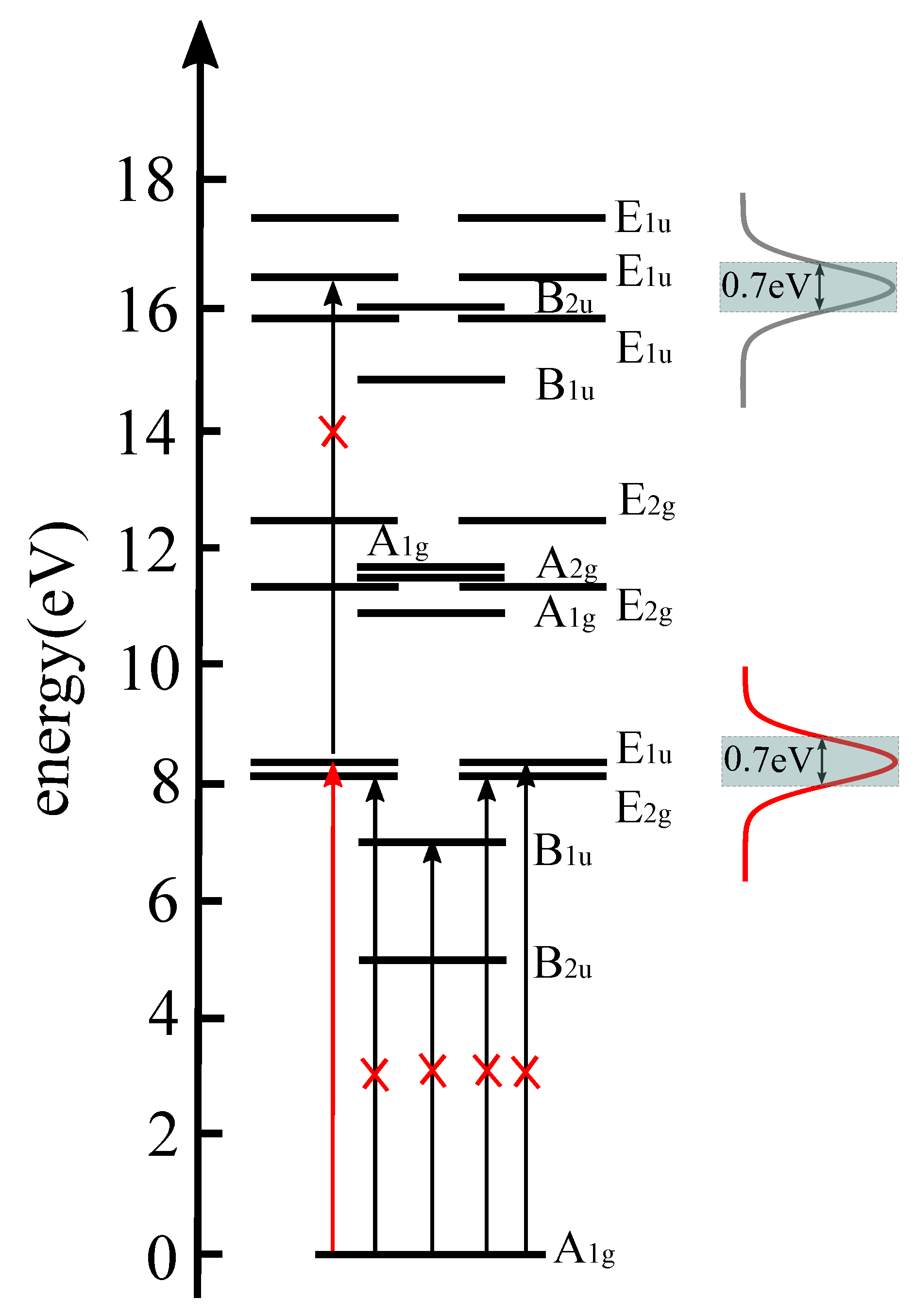
The spectral profiles (Equation (44)) are shown in Figure 2, together with the levels of the lowest electronic states of benzene, and their IRREPs. These energies have been calculated by means of the CASSCF(6,6) level of quantum chemistry, with aug-cc-PVTZ basis. Apparently, the broad bandwidths of the laser pulses cover several energy levels, but the present target state is the only state with I R R E P e = E 1 u + . All other states within the laser bandwidths have different IRREPs. The chosen circular polarizations of the present laser pulses then imply selective population transfer from the ground state ( I R R E P g = A 1 g ) exclusively to the target state ( I R R E P e = E 1 u + )—this is indicated by the vertical arrow in Figure 2. All other transitions are dipole-forbidden—these are symbolized by vertical arrows that are crossed out in Figure 2.
The condition in Equation (29) for the sum of the two laser pulses then yields the electric field of the designated resonant π -pulse,
ϵ π ( t ) = ϵ π x ( t ) , ϵ π y ( t ) , 0 = ϵ b s b ( t ) + ϵ r s r ( t ) · cos ω ( t t b ) , sin ω ( t t b ) , 0 .
Next, we invoke the two-state ( g , e + ) approximation, i.e., we assume that the laser pulses induce exclusively transitions between the ground state | Ψ g and the selective excited target state | Ψ e + = | Ψ E 1 u + . Implicitly, this approximation makes use of the so-called rotating wave approximation (RWA) that excludes transitions from | Ψ g to the degenerate excited state | Ψ e = | Ψ E 1 u . The validity of the RWA has been tested by excellent agreement of numerically accurate solutions of the TDSE (Equation (10)) with and without the RWA [19]. Moreover, the durations τ = τ b = τ r of the laser pulses imply sufficiently narrow widths Γ = 0.5 / τ that exclude dipole-allowed one-photon transitions to any other excited states. We assume that multi-photon processes such as ladder climbing to more excited states are negligible—the test of this assumption is left to future accurate model simulations. Using the two-state approximation with transition dipole matrix elements in Equation (41) for selective excitation from the ground state | Ψ g to the target state | Ψ e + = | Ψ E 1 u + , we obtain the specific form of the 2 × 2 Hamilton matrix in Equation (13),
H ( t ) = E g ϵ b s b ( t ) + ϵ r s r ( t ) e i ω ( t t b ) d / 2 ϵ b s b ( t ) + ϵ r s r ( t ) e i ω ( t t b ) d / 2 E e + .
The solution in Equation (19) of the TDSE (Equation (10)) with the initial condition in Equation (11) yields the coefficients [42]
c g ( t ) = cos d ϵ b t i t d t s b ( t ) + ϵ r t i t d t s r ( t ) / 2 e i E g ( t t b ) / , c e ( t ) = i sin d ϵ b t i t d t s b ( t ) + ϵ r t i t d t s r ( t ) / 2 e i E e ( t t b ) / = sin d ϵ b t i t d t s b ( t ) + ϵ r t i t d t s r ( t ) / 2 e i E e ( t t b ) / + i π / 2 .
In the following, we set E g = 0 , for convenience. Equation (45) then simplifies to
c g ( t ) = cos d ϵ b t i t d t s b ( t ) + ϵ r t i t d t s r ( t ) / 2 , c e ( t ) = i sin d ϵ b t i t d t s b ( t ) + ϵ r t i t d t s r ( t ) / 2 e i Δ E ( t t b ) / = i sin d ϵ b t i t d t s b ( t ) + ϵ r t i t d t s r ( t ) / 2 e 2 π i ( t t b ) / T .
The new strategy aims at complete g e population transfer by the two laser pulses, with exclusive population of the excited target state, Equation (18). Hence,
| c e ( t f ) | 2 = 1
or equivalently
d ϵ b t i t f d t s b ( t ) + ϵ r t i t f d t s r ( t ) / 2 = π d ( ϵ b τ b + ϵ r τ r ) / = π d ϵ π τ π / = π / 2 ,
(cf. Equations (14) and (18)). In the first part of Equation (50), we use the result
+ d t s b ( t ) = 2 π τ b + d t s r ( t ) = 2 π τ r
for Gaussian shape functions (Equation (36)) with parameters for the durations τ b and τ r , respectively. In the second part of Equation (50), we use the product ϵ π τ π of the field amplitude times the parameter for the duration of the π -pulse that yields the same result as the combined two laser pulses, i.e., complete population transfer from | Ψ g to | Ψ e + , with transition dipole matrix elements Ψ g | d x | Ψ e + = d / 2 and Ψ g | d y | Ψ e + = i d / 2 . Using Equation (50), the concept in Equation (29) can be rewritten as the constraint between the two pulses
ϵ b τ b + ϵ r τ r = ϵ π τ π .
Since our proof-of-principle is for the special case of equal durations of the laser pulses ( τ b = τ r = τ π = τ ), Equation (52) simplifies to the condition
ϵ b + ϵ r = ϵ π .
Accordingly, if the reference field amplitude of the π -pulse is equal to ϵ π and the field amplitude of the first pulse is equal to ϵ b , then the second laser pulse that restores symmetry should have the same shape and the same duration as the first pulse, and its field amplitude ϵ r should “fill the gap” between ϵ b and ϵ π .
As a summary, Equations (50)–(53) provide the proof-of-existence for the new strategy, i.e., if the first resonant right (+) circularly polarized laser pulse with field amplitude ϵ b and with Gaussian shape function and with parameter τ b for the duration breaks the electronic structure symmetry of the ground state, then one can employ the second resonant right (+) circularly polarized laser pulse with field amplitude ϵ r = ϵ π ϵ b and with Gaussian shape function with the same parameter τ r = τ b for the duration in order to restore symmetry in the electronic excited state. The success depends on the condition in Equation (33), i.e., the time delay between the laser pulses must be equal to an integer number N of the periods T of charge migration, or on the equivalent conditions in Equations (31)–(35).
Finally, let us investigate the consequences for the new strategy if the conditions in Equations (31)–(35) are not satisfied, i.e., the second pulse is centered at t r = t r + t with time delay t d = t d + t = N T + t due to additional quasi-field-free propagation from t c = 0 to t . For this purpose, we employ the expression (Equation (25)) of the evolution operator U ( t f , t i ) in terms of the product U r ( t f , t ) U f ( t , t c ) U b ( t c , t i ) of the evolution operators for the first laser pulse, for quasi-field free evolution, and for the second laser pulse. In passing, this approach also yields an illuminating alternative proof of Equations (51)–(53). We need to determine the matrix representations of the time evolution operators U r ( t f , t ) , U f ( t , t c ) and U b ( t c , t i ) , or in the present two-state ( g , e ) approximation, the 2 × 2 matrices U r g e ( t f , t ) , U f g e ( t , t c ) and U b g e ( t c , t i ) . For this purpose, it is first helpful to determine the coefficients at the central time t c ,
c g ( t c ) = cos 1 2 d ϵ b t i t c d t s b ( t ) / = cos π 2 d ϵ b τ b / , c e ( t c ) = i sin 1 2 d ϵ b t i t d t s b ( t ) / e 2 π i ( t c t b ) / T = i sin π d ϵ b τ b / e 2 π i N / 2 = i sin π d ϵ b τ b / if N = 2 , 4 , 6 , ( even ) i sin π d ϵ b τ b / if N = 1 , 3 , 5 , ( odd ) .
Gratifyingly, this is in accord with the general result, Equation (17), with parameters
α = π d ϵ b τ b
for the amplitudes, and
η g ( t c ) = 0 , Δ η e ( t c ) = η e ( t c ) = π / 2 if N = 1 , 3 , 5 , ( odd ) + π / 2 if N = 2 , 4 , 6 , ( even )
for the phases and phase differences. The derivation of Equations (54)–(56) employs the conditions in Equations (33) and (34), i.e., the time delay between the two laser pulses must be equal to an integer number N times the period T for charge migration. The corresponding unitary matrix U b g e ( t c , t i ) , Equation (28), for propagating the initial coefficients c ( t i ) , Equation (11), to c ( t c ) , Equation (54), is
U b g e ( t c , t i ) = cos α ± i sin α ± i sin α cos α .
The first column of the matrix in Equation (57) is imposed by the coefficients in Equation (54), the second column is due to the unitarity of U b g e ( t c , t i ) . Likewise, the final coefficients c k ( t f ) = c e ( t f ) δ k e = e i η e ( t f ) δ k e e i η e f δ k e imply the unitary matrix for propagating from t i to t f (cf. Equation (49)),
U g e ( t f , t i ) = e i η e f 0 1 1 0
with irrelevant phase factor e i η e f . The separation in Equation (22) of the evolution operator U g e ( t f , t i ) into two parts for symmetry breaking and restoration then yields the evolution operator for propagating from t c to t f ,
U r g e ( t f , t c ) = e i η e f ± i sin α cos α cos α ± i sin α = ± i e i η e f cos ( π / 2 α ) i sin ( π / 2 α ) i sin ( π / 2 α ) cos ( π / 2 α ) .
In the second part of Equation (59), we use the symmetry relations sin α = cos ( π / 2 α ) and cos α = sin ( π / 2 α ) . The second part of Equation (59) for time propagation due to the second laser pulse thus takes the same form as Equation (57) for the first laser pulse, except for the different but irrelevant phase factor ± i e i η e f . That means that the effect of the second laser pulse is formally equivalent to the first pulse, but the angle α must be replaced by π / 2 α . Equation (52) shows that this substitution is equivalent to replacing ϵ b τ b by ϵ π τ π ϵ r τ r or, if one uses the same parameters for the laser durations, τ b = τ π = τ r then it is equivalent to replacing ϵ b by ϵ π ϵ r . As anticipated, this requirement is equivalent to Equations (52) and (53).
Now, let us add the evolution operator for quasi-field-free evolution during the additional time from t c = 0 to t between the laser pulses (cf. Equations (25) and (26)),
U f g e ( t , t c ) = 1 0 0 e i Δ E t / h = 1 0 0 e 2 π i t / T 1 0 0 e i η .
The modified final coefficients at time t f = t f + t are then obtained as
c g ( t f ) c e ( t f ) = U r g e ( t f , t ) U f g e ( t , t c ) U b g e ( t c , t i ) 1 0 = ± i cos α sin α ( 1 + e i η ) e i η e f ( cos 2 α + sin 2 α · e i η ) e i η e f .
The modified final populations are
P e ( t f ) = | c e ( t f ) | 2 = cos 2 α + sin 2 α · e i η · cos 2 α + sin 2 α · e i η = 1 2 cos 2 α sin 2 α ( 1 cos η ) = 1 2 P g ( t c ) P e ( t c ) [ 1 cos ( 2 π t / T ) ] .
Accordingly, the goal of symmetry restoration in the target excited state with population P e ( t f ) = 1 is obtained at delay times t d = t r t b = N T between the laser pulses that correspond to integer numbers of periods of charge migration, or at delay times t d = t d + t that are prolongated by or additional full periods T , 2 T , 3 T , etc. In all other cases where t T , 2 T , 3 T , etc., the final population P e ( t f ) is less than 1, that means the final state remains a superposition of the ground and excited states with different I R R E P g and I R R E P e , i.e., the second pulse was unable to restore electronic structure symmetry, as illustrated in Figure 1.

3. Results and Discussions

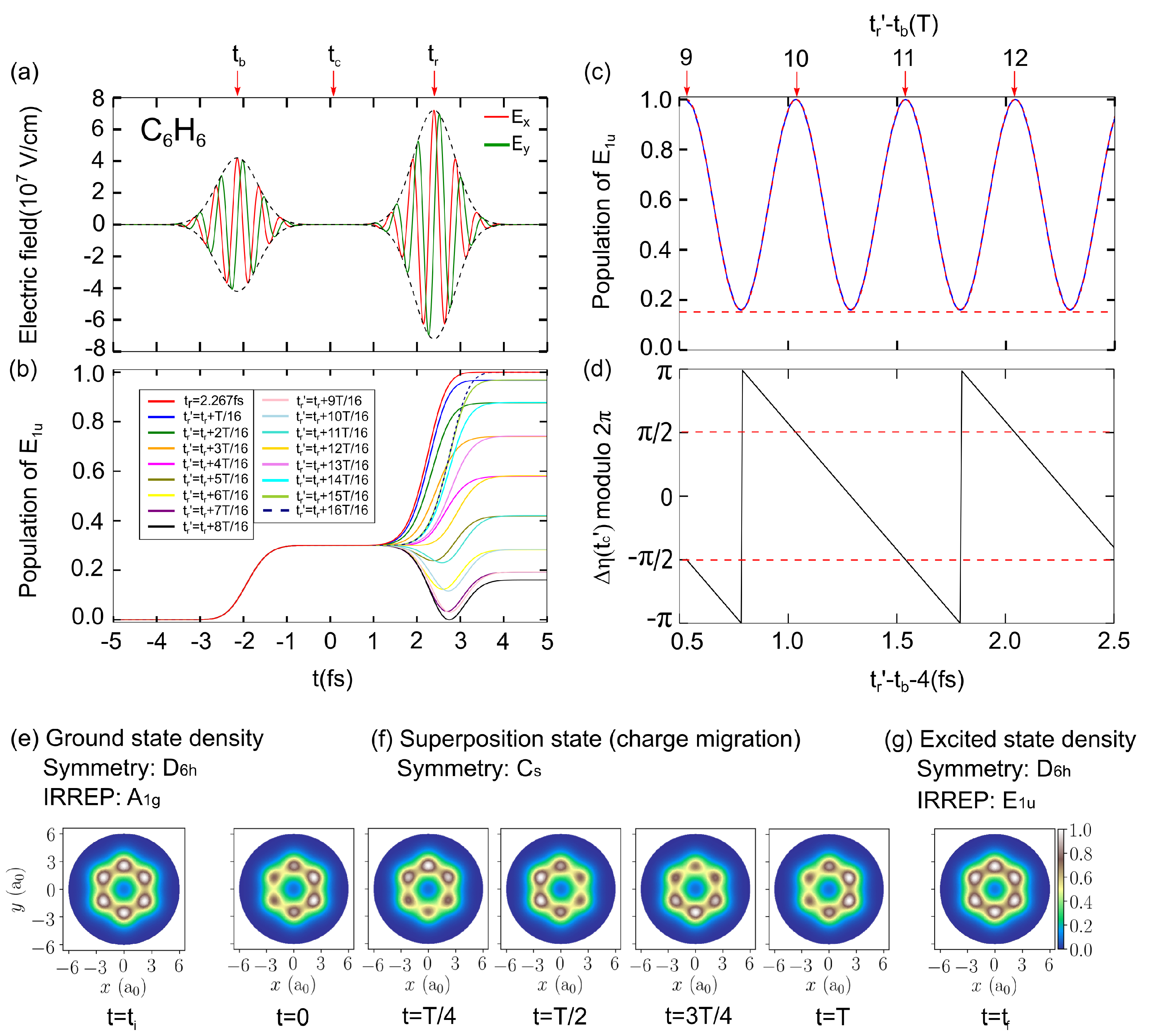
This section has two parts. First, we apply the theory of Section 2 to demonstrate successful quantum control of breaking and restoring the D 6 h symmetry of the electronic structure of the model benzene in its electronic ground and excited states with different I R R E P s A 1 g and E 1 u . This part consists of three steps: (i) the symmetry breaking by a circularly right (+) polarized laser pulse and the resulting periodic charge migration; (ii) the design of the laser pulse for symmetry restoration; and (iii) the quantum dynamics simulation of the laser driven symmetry restoration. The purpose of this first part is to provide a proof-of-principle of the new strategy that has been developed in Section 2, for the example of the model benzene. The second part presents an in-depth-investigation of the condition in Equation (33) for the time delay between the two laser pulses, t d = N T , i.e., the time delay must be equal to an integer number of period T of charge migration. We show that this condition must be satisfied with precision of a few attoseconds. The results for both parts are documented in Figure 3. The layout of Figure 3 is the same as corresponding figures in Refs. [19,20,21], but the results are of course entirely different, i.e., Figure 3 documents a new mechanism of symmetry restoration, different from those of Refs. [19,20,21]. The values of the parameters of the laser pulses that are applied for the proof-of-principle are listed in the caption of Figure 3.

3.1. The Proof-of-Principle for Quantum Control of Symmetry Breaking and Restoration of Molecules in Electronic Ground and Excited States with Different I R R E P s

Our proof-of-principle uses the concept and theory that are developed in Section 2, with application to the model benzene as described in Section 1 and Section 2. The proof consists of three steps that implement various results of Section 2. The presentation below documents the key results in a straightforward manner, with references to several key expressions, but without repetition of the derivation. The reader is expected to be familiar with the context developed in Section 2.
Step (i): The electronic structure of benzene in its initial ground state ( I R R E P g = A 1 g ) is illustrated by a contour plot of its one-electron density in the molecular plane in Figure 3e. One readily recognizes its D 6 h symmetry.
The x- and y-components and the envelope of the electric field of the first circularly right (+) polarized laser pulse (Equation (42)) that breaks the D 6 h symmetry are shown in the left of Figure 3a. This pulse is centered at t b = 4.5 T = 2.267 fs. Its parameters are chosen rather arbitrarily, within the frame of the general rules explained in Section 1 and Section 2. The pulse thus serves as “general” example, quite different from the special π / 2 pulse that has been employed in Ref. [21]. Consequently, its effect of symmetry breaking and launching charge migration should also be considered as “general”, providing a “generic example” for the challenge of designing a second laser pulse that stops charge migration and restores symmetry. In other words, the present example lends itself for a rather general proof-of-principle.
The first laser pulse breaks D 6 h symmetry by preparing the superposition (Equation (5)) of the electronic ground and excited states with I R R E P s A 1 g and E 1 u , here with probabilities P g ( t c = 0 ) = 0.7 and P e ( t c = 0 ) = 0.3 at central time t c = 0 (cf. Equation (16)). The laser-induced increase of P e ( t ) from the initial value zero to P e ( t c = 0 ) = 0.3 is documented in Figure 3b. The one-electron density of the superposition state (Equation (5)) at t c is illustrated in the first panel of Figure 3e. Symmetry breaking is obvious, i.e., the superposition state (Equation (5)) can no longer be assigned to the original D 6 h symmetry. Since it is not an eigenstate, it is non-stationary. This gives rise to periodic charge migration with period T, as illustrated in Figure 3f by five snapshots of the one-electron density at times t = 0 , T / 4 , T / 2 , 3 T / 4 , T . On first glance, these snapshots may suggest that the superposition (Equation (5)) may have C 2 v symmetry, but additional snapshots at arbitrary times t [ 0 , T ] reveal that the superposition (Equation (5)) evolves with C s symmetry: the first laser pulse breaks all symmetry elements except the molecular plane as mirror plane. The challenge is thus to design the second laser pulse that stops charge migration and restores symmetry by transferring the superposition state (Equation (5)) to the excited target state (Equation (6)).
Step (ii): The second laser pulse for symmetry restoration is constructed according to the recipe derived in Section 2.2 and Section 2.3.
First, it should be circularly right (+) polarized, similar to the first laser pulse, Equation (42). The laser parameters of the two pulses are the same, with two exceptions.
Second, the pulse is centered at t r = t b , and the time delay t d between the two laser pulses must be equal to an integer number N of period T of charge migration. In the present case, we choose
t d = t r t b = 9 T ,
that means
t r = t b = 4.5 T ;
compare with Equations (33) and (34). We note in passing that the conditions in Equations (63) and (64) imply the phase difference Δ η ( t c ) mod 2 π = ± π / 2 for the coefficients c e ( t c ) and c g ( t c ) of the superposition state (Equation (5)) at central time t c ; see Equation (35) and the derivation in Equation (54). This result is confirmed in Figure 3d.
Third, the field strength ϵ r is determined according to the rule in Equation (53),
ϵ r = ϵ π ϵ b
where ϵ π is the field strength of a circularly right (+) polarized π -pulse with Gaussian shape,
ϵ π = π · 2 d τ ,
in accord with Equation (50) (cf. Ref. [42]). The value of the parameter for the laser duration, τ = 0.47 fs, together with the value of the transition dipole d = 2.0576 e a 0 , yields the field amplitude of the π -laser pulse, ϵ π = 11.399 × 10 7 V/cm. Subtraction of the field amplitude of the laser pulse for symmetry breaking, ϵ b = 4.207 × 10 7 V/cm, then yields the field strength of the laser pulse for symmetry restoration, ϵ r = 7.192 × 10 7 V/cm. It is illuminating to compare the population transfers between the electronic ground and excited states, namely 0.30 and 0.70 , which are achieved by these pulses, with the values 0.0037 for the weak field strengths ϵ b = ϵ r = 4.42 × 10 6 V/cm that are employed in Ref. [19]. Assuming the weak field limit, the population transfers should increase linearly with intensity, i.e., one would expect the value 0.0037 × ( 42.07 / 4.42 ) 2 = 0.33 and 0.0037 × ( 42.07 / 4.42 ) 2 = 0.98 . The deviations from the values 0.30 and 0.70 show that while the intensity of the pulse for symmetry breaking may still be considered as “weak”, the required high field strength of the pulse for symmetry restoration is well beyond that limit.
The predicted laser pulse for symmetry restoration is shown in Figure 3a as second pulse, together with the laser pulse for symmetry breaking as first laser pulse. As anticipated already in Figure 1, the rules in Equations (53) and (65) imply that the second pulse is a bit stronger than the first one.
Step (iii): As decisive effect of the laser pulse for the symmetry restoration designed in Section 2.2, Figure 3b documents the laser driven evolution of the population of the excited state P e ( t ) in the superposition state (Equation (5)), from the value P e ( t c ) = 0.3 to P e ( t f ) = 1 . This is a key result: it implies complete and exclusive population of the excited state with D 6 h symmetry and I R R E P e = E 1 u . This provides the proof-of-principle, i.e., the well-designed (see Section 2.2) second laser pulse (Figure 3a) restores D 6 h symmetry by exciting the model benzene from the superposition state (Equation (5)) to the target state with I R R E P e I R R E P g . At the same time, it stops charge migration because the target state is an electronic eigenstate, i.e., it is stationary. The one-electron density of the target state is shown in Figure 3g. Its D 6 h symmetry is obvious. There are, however, tiny differences between the initial (Figure 3e) and the final (Figure 3g) electron densities—this is a consequence of the different I R R E P s A 1 g and E 1 u of the initial and final states, respectively.

3.2. The Requirement of Attosecond Precision for the Proper Time Delay Between the Laser Pulses for Electronic Structure Symmetry Breaking and Restoration

The proof-of-principle (Section 3.1) employs the perfectly synchronized second laser pulse for symmetry restoration which has been designed according to the recipe derived in Section 2. In particular, its time delay with respect to the first laser pulse that breaks symmetry satisfies the condition in Equation (63), in accord with the general rule in Equation (33). In this subsection, we investigate the consequences of violations of the condition in Equation (63). For this purpose, let us assume that the second laser pulse is centered at
t r = t r + t
with additional time t between the laser pulses, that means with additional time for the molecule to evolve in quasi-field-free environment, from t c = 0 to t . The corresponding time delay is
t d = t d + t ,
the new final time is
t f = t f + t ,
and the new “central time” is
t c = ( t r + t b ) / 2 = t c + t / 2 = t / 2 .
Figure 3b shows the resulting time evolutions of the populations P e ( t ) of the excited state in the superposition state (Equation (5)) for altogether sixteen different values of additional time, t = k T / 16 , k = 1 , 2 , , 16 . The results of this systematic investigation are obtained by solving the TDSE (Equation (10)) by the numerical techniques developed in Ref. [19]. Apparently, the vast majority of these examples yield final populations
P e ( t f ) 1 for t = k T / 16 , k = 1 , 2 , , 15 .
That means the molecule is left in a superposition state such as Equation (5), not only after the first pulse that means at t c , but also after the second pulse at t f . Hence, the final state is not a pure state, but it is “contaminated” by both the ground and excited states with different I R R E P s , i.e., the second laser pulse was unable to restore symmetry.
Figure 3b also shows one exceptional case ( k = 16 ) where t = T . In this case, the final population of the excited state is
P e ( t f ) = 1 for t = T
implying symmetry restoration. The corresponding time delay
t d = t r t b = 10 T
is again an integer multiple of the period T for charge migration. The results in Equations (71)–(73) documented in Figure 3b thus confirm the condition in Equation (33), i.e., to achieve symmetry restoration, the time delay between the two laser pulses must satisfy the requirement t d = N T or more generally
t d = N T .
The sixteen results for the final populations P e ( t f ) obtained in Figure 3b are plotted versus time delay t d , Equation (65), in Figure 3c, together with corresponding results for a broader range of time delays. Figure 3c also shows a comparison of these results, which are obtained by quantum dynamics simulations, with the analytical result in Equation (62). The agreement is seen to be almost perfect, the deviations are smaller than the graphical resolution. We consider this agreement as double triumph, both for the robustness of the numerical method for quantum dynamics simulation that has been developed in Ref. [19], and also for the analytical theory derived in Section 2.3.
According to Figure 3c and the analytical result in Equation (62), perfect symmetry restoration requires perfect time delays, Equations (33) and (74). In practice, one may allow small deviations from the ideal value P e ( t f ) = 1 , for example one may accept results P e ( t f ) > 0.99 as “good enough” for “almost perfect symmetry restoration”. The limit P e ( t f ) > 0.99 would allow small deviations Δ t d < 0.035 T from the ideal time delays. The present value of the period T = 504 as thus implies that the time delay between the laser pulses should obey the condition in Equation (33) and (74) with accuracy of few attoseconds. Indeed, this time resolution was achieved experimentally by high-contrast Ramsay interferometry, which was thereby shown to be suitable for symmetry restoration [19].
Finally, Figure 3d documents the validity of the equivalent conditions in Equations (35) and (56) for the phase difference Δ η ( t c ) of the coefficients of the superposition state (Equation (5)) at the central time t c , Equation (70). As anticipated, the values of Δ η ( t c ) mod 2 π at the central times t c = T / 2 , T , 3 T / 2 , 2 T , etc. and the corresponding time delays t d = 9 T , 10 T , 11 T , 12 T , etc. alternate according to π / 2 , + π / 2 , π / 2 , + π / 2 , etc. For any other values of the times t c , t d and the phase difference Δ η ( t c ) mod 2 π , the second pulse does not allow symmetry restoration.

4. Conclusions

This paper presents a new strategy for the restoration of the symmetry of electronic structure by means of a well-designed laser pulse, after symmetry was broken by a first laser pulse, which excites the electronic ground state to a superposition of the ground state and an excited state with different I R R E P s . The superposition state is non-stationary; it represents periodic charge migration with period T. Typical values of T for electronic superposition states are in the time domain from several hundred attoseconds to few femtoseconds. Symmetry is restored by the second laser pulse, which excites the superposition state to the excited state. The net effect of the two laser pulses can be summarized as an excitation of the electronic ground state to the excited state, with I R R E P e I R R E P g . This observation suggests that, as a necessary condition for this new type of symmetry restoration, the second laser pulse must be designed such that the sum of the first and second laser pulses add up to a π -pulse. There are many ways to satisfy this condition. In the present application to the model benzene, both laser pulses are designed as circularly right (+) polarized laser pulses, with the same Gaussian shapes, the same parameters for the duration, the same resonant carrier frequencies, the same carrier envelope phases, but with two different temporal centers and with different field strengths. Specifically, the time delay between the temporal centers of the two laser pulses must be equal to an integer number of periods T. This condition must be satisfied with precision of few attoseconds. The experimental feasibility of this high accuracy is demonstrated in Ref. [19]. The condition for the field strength of the second laser pulse is that the sum of the field strengths of the first and second laser pulses must add up to the field strength of the circularly polarized π -pulse that otherwise has the same parameters as the first and second pulses. One may thus consider the two laser pulses as “fractional π -pulses”. Previously, it has been shown that fractional π -pulses are useful for other purposes as well, e.g., for laser generation of hybrid orbitals [47].
The present proof-of-principle of the new strategy, together with the alternative previous strategies [19,20,21], should stimulate the search for alternative approaches to laser symmetry restoration. As a working hypothesis, the present concept should allow several extensions, e.g., the fractional π -pulse for symmetry restoration may be designed with weaker or stronger field strengths that are compensated by longer or shorter duration, respectively, or one might employ the carrier envelope phase as a control knob in order to compensate the effect of time delays with non-integer multiples of the period T. By extrapolation of the concept and derivations of this manuscript, the field of laser symmetry breaking and restoration leads into new territories of research that allow rich discoveries. From the experimental point of view, one should keep in mind that the present new concept of laser control from symmetry breaking via charge migration to symmetry restoration is general and should apply to many other rigid molecules—the present example of the benzene molecule should stimulate the search for candidates with more suitable parameters for experimental verification.

Author Contributions

J.C.T. and J.M. proposed the new strategy of quantum control of electronic structure symmetry breaking and restoration; J.M. discovered the concept, derived most part of the theory and wrote the zero order draft; and C.L. obtained the important Equation (62), carried out all the quantum dynamics simulations and prepared the figures (the snapshots of the one-electron densities were plotted by J.C.T.). All co-authors together prepared the final version of the manuscript.

Funding

This work profited from financial support in part by the National Key Research and Development Program of China (No. 2017 Y F A 0304203 ), the program for Changjiang Scholars and Innovative Research Team (No. IRT17R70), the 111 project (Grant No. D 18001 ), the Fund for Shanxi “1331 Project” Key Subjects, and the National Natural Science Foundation of China (No. 11434007).

Conflicts of Interest

The authors declare no conflict of interest.

References

  1. Ivanov, M.; Corkum, P.B.; Dietrich, P. Coherent Control and Collapse of Symmetry in a Two-Level System in an Intense Laser Field. Laser Phys. 1993, 3, 375–380. [Google Scholar]
  2. Weinacht, T.C.; Ahn, J.; Bucksbaum, P.H. Measurement of the Amplitude and Phase of a Sculpted Rydberg Wave Packet. Phys. Rev. Lett. 1998, 80, 5508–5511. [Google Scholar] [CrossRef]
  3. Elghobashi, N.; González, L.; Manz, J. Quantum model simulations of symmetry breaking and control of bond selective dissociation of FHF using IR+UV laser pulses. J. Chem. Phys. 2004, 120, 8002–8014. [Google Scholar] [CrossRef] [PubMed]
  4. Arasaki, Y.; Takatsuka, K. Optical conversion of conical intersection to avoided crossing. Phys. Chem. Chem. Phys. 2010, 12, 1239–1242. [Google Scholar] [CrossRef] [PubMed]
  5. Arasaki, Y.; Wang, K.; McKoy, V.; Takatsuka, K. Monitoring the effect of a control pulse on a conical intersection by time-resolved photoelectron spectroscopy. Phys. Chem. Chem. Phys. 2011, 13, 8681–8689. [Google Scholar] [CrossRef] [PubMed]
  6. Alnasser, A.S.; Kübel, M.; Siemering, R.; Bergues, B.; Kling, N.G.; Betsch, K.J.; Deng, Y.; Schmidt, J.; Alahmed, Z.A.; Azzeer, A.M.; et al. Subfemtosecond steering of hydrocarbon deprotonation through superposition of vibrational modes. Nat. Commun. 2014, 5, 3800. [Google Scholar] [CrossRef]
  7. Pertot, Y.; Schmidt, C.; Matthews, M.; Chauvet, A.; Huppert, M.; Svoboda, V.; Conta, A.; Tehlar, A.; Baykusheva, D.; Wolf, J.-P.; et al. Time-resolved x-ray absorption spectroscopy with a water window high-harmonic source. Science 2017, 355, 264–267. [Google Scholar] [CrossRef]
  8. Cederbaum, L.S.; Zobeley, J. Ultrafast charge migration by electron correlation. Chem. Phys. Lett. 1999, 307, 205–210. [Google Scholar] [CrossRef]
  9. Remacle, F.; Levine, R.D. An electronic time scale in chemistry. Proc. Natl. Acad. Sci. USA 2006, 103, 6793–6798. [Google Scholar] [CrossRef]
  10. Chelkowski, S.; Yudin, G.L.; Bandrauk, A.D. Observing electron motion in molecules. J. Phys. B 2006, 39, S409–S417. [Google Scholar] [CrossRef]
  11. Barth, I.; Manz, J. Periodic Electron Circulation Induced by Circularly Polarized Laser Pulses: Quantum Model Simulations for Mg Porphyrin. Angew. Chem. Int. Ed. 2006, 45, 2962–2965. [Google Scholar] [CrossRef] [PubMed]
  12. Kanno, M.; Kono, H.; Fujimura, Y. Control of π-Electron Rotation in Chiral Aromatic Molecules by Nonhelical Laser Pulses. Angew. Chem. Int. Ed. 2006, 45, 7995–7998. [Google Scholar] [CrossRef] [PubMed]
  13. Mineo, H.; Lin, S.H.; Fujimura, Y. Vibrational effects on UV/Vis laser-driven π-electron ring currents in aromatic ring molecules. Chem. Phys. 2014, 442, 103–110. [Google Scholar] [CrossRef]
  14. Despré, V.; Marciniak, A.; Loriot, V.; Galbraith, M.C.E.; Rouzée, A.; Vrakking, M.J.J.; Lépine, F.; Kuleff, A.I. Attosecond Hole Migration in Benzene Molecules Surviving Nuclear Motion. J. Phys. Chem. Lett. 2015, 6, 426–431. [Google Scholar] [CrossRef] [PubMed]
  15. Kraus, P.M.; Mignolet, B.; Baykusheva, D.; Rupenyan, A.; Horny, L.; Penka, E.F.; Grassi, G.; Tolstikhin, O.I.; Schneider, J.; Jensen, F.; et al. Measurement and laser control of attosecond charge migration in ionized iodoacetylene. Science 2015, 350, 790–795. [Google Scholar] [CrossRef] [PubMed]
  16. Ueda, K. To catch and smash charge on the hop. Science 2015, 350, 740–741. [Google Scholar] [CrossRef] [PubMed]
  17. Jia, D.; Manz, J.; Paulus, B.; Pohl, V.; Tremblay, J.C.; Yang, Y. Quantum control of electronic fluxes during adiabatic attosecond charge migration in degenerate superposition states of benzene. Chem. Phys. 2017, 482, 146–159. [Google Scholar] [CrossRef]
  18. Golubev, N.V.; Despré, V.; Kuleff, A. Quantum control with smoothly varying pulses: General theory and application to charge migration. J. Mod. Opt. 2017, 64, 1031–1041. [Google Scholar] [CrossRef]
  19. Liu, C.; Manz, J.; Ohmori, K.; Sommer, C.; Takei, N.; Tremblay, J.C.; Zhang, Y. Attosecond Control of Restoration of Electronic Structure Symmetry. Phys. Rev. Lett. 2018, 121, 173201. [Google Scholar] [CrossRef]
  20. Liu, C.; Manz, J.; Tremblay, J.C. Progress in Ultrafast Intense Laser Science XIV; Yamanouchi, K., Martin, P., Sentis, M., Li, R., Normand, D., Eds.; Springer International Publishing: Cham, Switzerland, 2018; Volume 14, Chapter 7; pp. 117–141. ISBN 9783030037857. [Google Scholar]
  21. Bacic, Z.; Benoit, D.; Biczysko, M.; Bowman, J.; Bradforth, S.; Burd, T.; Chambaud, G.; Clary, D.; Crépin, C.; Dracinsky, M.; et al. Molecules in confinement in clusters, quantum solvents and matrices: General discussion. Faraday Discuss. 2018, 212, 569–601. [Google Scholar] [CrossRef]
  22. Bandrauk, A.D.; Chelkowski, S.; Corkum, P.B.; Manz, J.; Yudin, G.L. Attosecond Photoionization of a Coherent Superposition of Bound and Dissociative Molecular States. J. Phys. B 2009, 42, 134001. [Google Scholar] [CrossRef]
  23. Mendive-Tapia, D.; Vacher, M.; Bearpark, M.J.; Robb, M.A. Coupled electron-nuclear dynamics: Charge migration and charge transfer initiated near a conical intersection. J. Chem. Phys. 2013, 139, 044110. [Google Scholar] [CrossRef] [PubMed]
  24. Ulusoy, I.; Nest, M. Correlated Electron Dynamics: How Aromaticity Can Be Controlled. J. Am. Chem. Soc. 2011, 133, 20230–20236. [Google Scholar] [CrossRef] [PubMed]
  25. Hermann, G.; Liu, C.; Manz, J.; Paulus, B.; Pérez-Torres, J.F.; Pohl, V.; Tremblay, J.C. Multidirectional Angular Electronic Flux during Adiabatic Attosecond Charge Migration in Excited Benzene. J. Phys. Chem. A 2016, 120, 5360–5369. [Google Scholar] [CrossRef] [PubMed]
  26. Hermann, G.; Liu, C.; Manz, J.; Paulus, B.; Pohl, V.; Tremblay, J.C. Attosecond Angular Flux of Partial Charges on the Carbon Atoms of Benzene in Non-Aromatic Excited States. Chem. Phys. Lett. 2017, 683, 553–558. [Google Scholar] [CrossRef]
  27. Alber, G.; Ritsch, H.; Zoller, P. Generation and detection of Rydberg wave packets by short laser pulses. Phys. Rev. A 1986, 34, 1058–1064. [Google Scholar] [CrossRef]
  28. Noordam, L.D.; Duncam, D.I.; Gallagher, T.F. Ramsey fringes in atomic Rydberg wave packets. Phys. Rev. A. 1992, 45, 4734–4737. [Google Scholar] [CrossRef]
  29. Corkum, P.B. Plasma perspective on strong-field multiphoton ionization. Phys. Rev. Lett. 1993, 71, 1994–1997. [Google Scholar] [CrossRef]
  30. Corkum, P.B.; Krausz, F. Attosecond science. Nat. Phys. 2007, 3, 381–387. [Google Scholar] [CrossRef]
  31. Krausz, F.; Ivanov, M. Attosecond physics. Rev. Mod. Phys. 2009, 81, 163–234. [Google Scholar] [CrossRef]
  32. Chelkowski, S.; Bredtmann, T.; Bandrauk, A.D. High-order-harmonic generation from coherent electron wave packets in atoms and molecules as a tool for monitoring attosecond electrons. Phys. Rev. A 2012, 85, 033404. [Google Scholar] [CrossRef]
  33. Schultz, T.; Vrakking, M. Attosecond and XUV Physics; Wiley-VCH: Weinheim, Germany, 2014; ISBN 9783527411245. [Google Scholar]
  34. Woodward, R.; Hoffmann, R. Die Erhaltung der Orbitalsymmetrie; Verlag Chemie: Weinheim, Germany, 1972; ISBN 3527253238. [Google Scholar]
  35. Halevi, E. Orbital Symmetry and Reaction Mechanism: The OCAMS View; Springer: Berlin, Germany, 1992; ISBN 9783642835681. [Google Scholar]
  36. Campbell, E.E.B.; Schmidt, H.; Hertel, I.V. Symmetry and Angular Momentum in Collisions with Laser Excited Polarized Atoms. Adv. Chem. Phys. 1988, 72, 37–114. [Google Scholar] [CrossRef]
  37. Al-Jabour, S.; Leibscher, M. Effects of Molecular Symmetry on Quantum Reaction Dynamics: Novel Aspects of Photoinduced Nonadiabatic Dynamics. J. Phys. Chem. A 2015, 119, 271–280. [Google Scholar] [CrossRef] [PubMed]
  38. Schleich, W.P.; Walther, H. Elements of Quantum Information; Wiley-VCH: Weinheim, Germany, 2007; ISBN 9783527407255. [Google Scholar]
  39. Brif, C.; Chakrabarti, R.; Rabitz, H. Control of quantum phenomena: Past, present and future. New. J. Phys. 2010, 12, 075008. [Google Scholar] [CrossRef]
  40. Shapiro, M.; Brumer, P. Quantum Control of Molecular Processes, 2nd ed.; Wiley-VCH: Weinheim, Germany, 2012; ISBN 9783527409044. [Google Scholar]
  41. Tannor, D.J. Introduction to Quantum Mechanics: A Time-Dependent Perspective; University Science Books: Sausalito, CA, USA, 2012; ISBN 10:1-891389-23-8. [Google Scholar]
  42. Barth, I.; Manz, J. Unidirectional Electronic Ring Current driven by a Few Cycle Circularly Polarized Pulse: Quantum Model Simulations for Mg-Porphyrine. J. Am. Chem. Soc. 2006, 128, 7043–7049. [Google Scholar] [CrossRef] [PubMed]
  43. Hermann, G.; Pohl, V.; Tremblay, J.C.; Paulus, B.; Hege, H.-C.; Schild, A. ORBKIT—A Modular Python Toolbox for Cross-Platform Post-Processing of Quantum Chemical Wavefunction Data. J. Comput. Chem. 2016, 37, 1511–1520. [Google Scholar] [CrossRef] [PubMed]
  44. Pohl, V.; Hermann, G.; Tremblay, J.C. An Open-Source Framework for Analyzing N-Electron Dynamics: I. Multi-Determinantal Wave Functions. J. Comput. Chem. 2017, 38, 1515–1527. [Google Scholar] [CrossRef]
  45. Hermann, G.; Pohl, V.; Tremblay, J.C. An Open-Source Framework for N-Electron Dynamics: II. Hybrid Density Functional Theory Configuration Interaction Methodology. J. Comput. Chem. 2017, 38, 2378–2387. [Google Scholar] [CrossRef]
  46. Hunter, J.D. Matplotlib: A 2D graphics environment. Comput. Sci. Eng. 2007, 9, 90–95. [Google Scholar] [CrossRef]
  47. Liu, C.; Manz, J.; Yang, Y. Laser Sculpting of Atomic sp, sp2, and sp3 Hybrid Orbitals. Chem. Phys. Chem. 2015, 16, 191–196. [Google Scholar] [CrossRef]
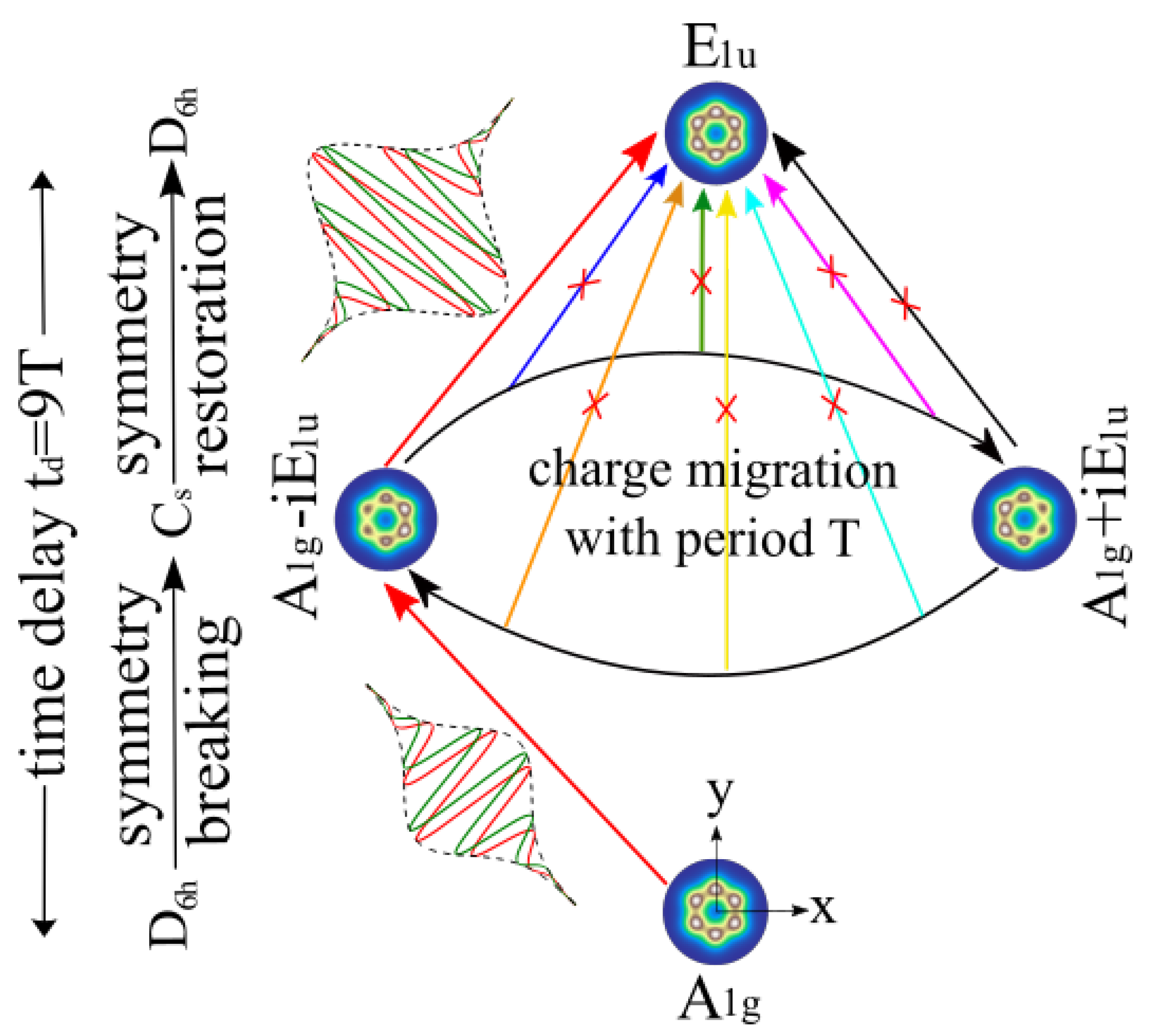
Figure 1. The concept for symmetry breaking of the electronic ground state and symmetry restoration in an electronic excited state by two laser pulses according to the new strategy. (Bottom) One-electron density of the oriented benzene molecule in the ground state labeled A 1 g (symmetry D 6 h , irreducible representation I R R E P g = A 1 g ). The first circularly-polarized laser pulse is centered at time t b = 4.5 T . It breaks symmetry by exciting the ground state to the superposition labeled “ A 1 g i E 1 u ” of the ground state and an excited state with I R R E P e = E 1 u . This laser excitation is symbolized by the first red arrow. The superposition state has symmetry C s . (Middle) Periodic charge migration from “ A 1 g i E 1 u ” via “ A 1 g + i E 1 u ” back to “ A 1 g i E 1 u ”, with period T = 504 as. This is symbolized by the two curved arrows, with snapshots of the one-electron densities for state “ A 1 g i E 1 u ” (left) at central time t = t c = 0 (and also at t = T , 2 T , etc.) and for state “ A 1 g + i E 1 u ” (right) at time t = T / 2 (and also at 3 T / 2 , 5 T / 2 , etc.) The second laser pulse centered at t r = 4.5 T restores D 6 h symmetry by transferring the superposition state to the excited state with I R R E P e = E 1 u . This laser excitation is symbolized by the second red arrow. (Top) One-electron density of the excited target state labeled E 1 u . The time delay t d = t r t b = N T between the centers of the laser pulses must be equal to an integer number N of periods T of charge migration, with precision of few attoseconds. Here, N = 9 . Any attempts to restore electronic structure symmetry at delay times that correspond to incomplete cycles of charge migration are useless—this is indicated by the crossed-out arrows. The Gaussian shape functions (dashed lines) and the x- and y-components of the electric field (red and green continuous lines) of the circularly-polarized laser pulses are also sketched. All densities were created using detCI@ORBKIT [43,44,45] and plotted using Matplotlib [46].
Applsci 09 00953 g001
Figure 2. (Left) Electronic energy levels of the lowest states of benzene, with assignment of the IRREPs. The present circularly polarized laser pulses yield exclusive population transfer from the electronic ground state A 1 g to the excited target state E 1 u + , illustrated by the vertical arrow. All other transitions to excited states that are within the spectral width of the laser pulses with different IRREPs are dipole forbidden, symbolized by vertical arrows that are crossed out. The two-photon process at 16.42 eV is also found to be off-resonance. (Right) Spectral profile of the laser pulses of duration 0.47 fs (red line), including a potential two-photon contribution at Δ E = 2 ω = 16.42 eV (grey line).
Applsci 09 00953 g002
Figure 3. Symmetry breaking of the electronic ground state of benzene labeled A 1 g (symmetry D 6 h , irreducible representation I R R E P g = A 1 g ) and symmetry restoration in an electronic excited labeled E 1 u (symmetry D 6 h , irreducible representation I R R E P e = E 1 u ) by two laser pulses according to the new strategy. (a) Gaussian envelopes (dashed lines) and the x- and y-components (red and green continuous lines) of the circularly right (+) polarized laser pulses centered at t b = 4.5 T and t r = + 4.5 T with period T = 504 as of charge migration. The parameter of the circularly right (+) polarized laser pulses (Equation (40)) are ϵ b = 4.207 × 10 7 V / cm , ϵ r = 7.192 × 10 7 V / cm , ω = 2 π / T , T = 504 as , τ b = τ r = 0.47 fs , t b = 4.5 T , t r = + 4.5 T . (b) Time evolution of the population of the excited state due to the first and second laser pulses shown in (a) for the case t r = + 4.5 T = 2.267 fs . The results for sixteen different times t r = t r + t where t = k T / 16 , k = 1 , 2 , , 16 are also shown. (c) Numerical results (continuous blue line) and analytical result (dotted red line, Equation (62)) for the final populations P e ( t f ) of the excited state at time t f = t f + t versus delay time t d = t r t b , in units of the period T (top abscissa) or fs (bottom abscissa, as in (d)). The results coincide within graphical resolution. (d) Phase difference Δ η ( t c ) = η e ( t c ) η g ( t c ) of the wave functions in electronic excited and ground states at the central time t c = ( t r + t b ) / 2 . (e) One-electron density of the electronic ground state of benzene labeled A 1 g . (f) Five snapshots of the one-electron density during periodic charge migration of the superposition of the ground state labeled A 1 g and the excited state labeled E 1 u during one period, from t = t c = 0 to T. (g) One-electron density of the excited target state labeled E 1 u . All densities were created using detCI@ORBKIT [43,44,45] and plotted using Matplotlib [46].
Applsci 09 00953 g003