Study on Low-Speed Steering Resistance Torque of Vehicles Considering Friction between Tire and Pavement


Abstract
:1. Introduction
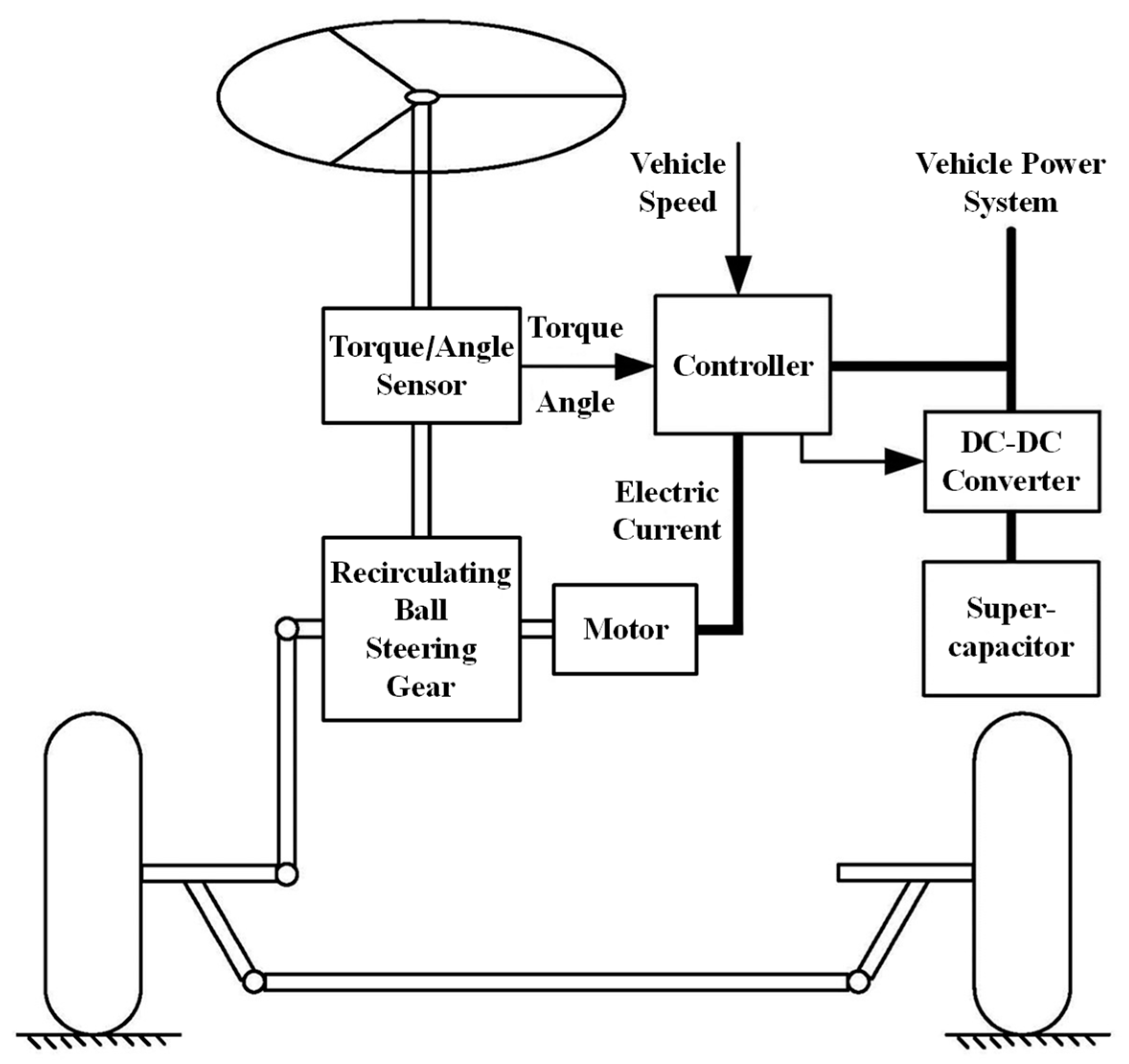
2. Structure and Working Principles of the SC-EPS System
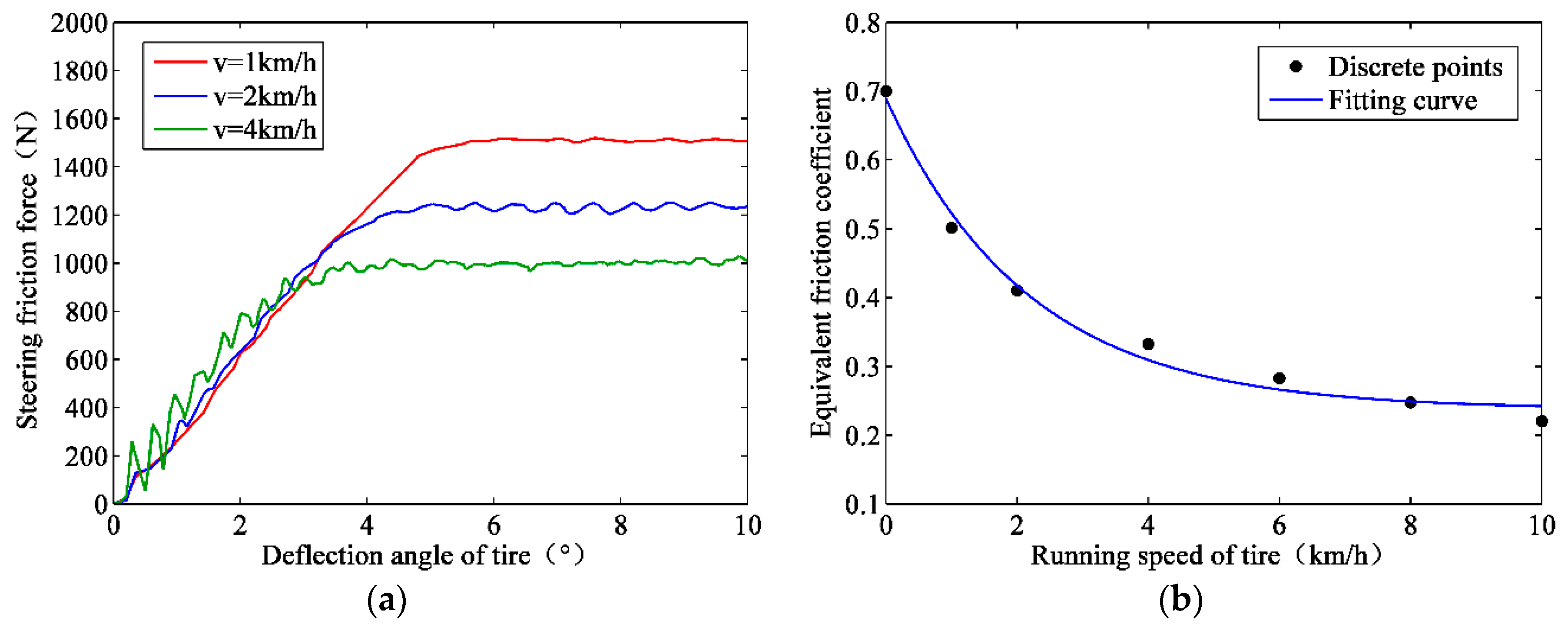
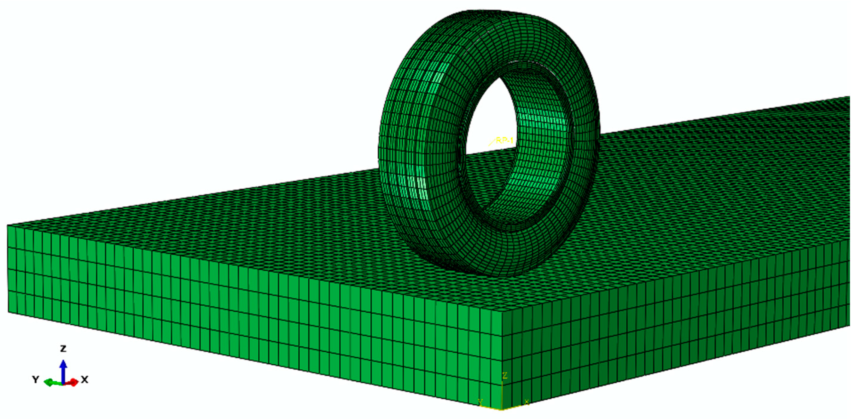
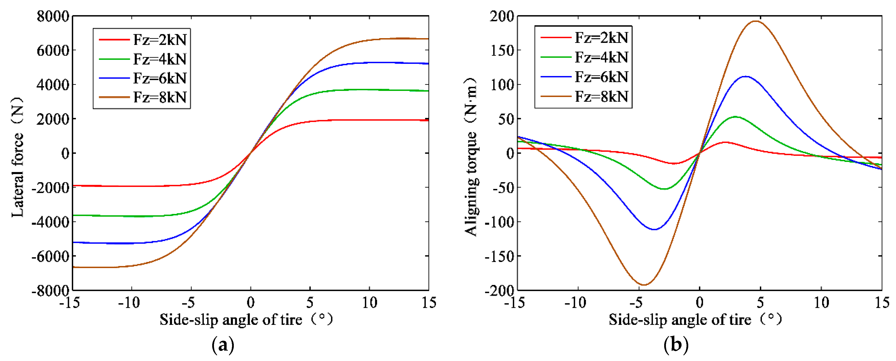
3. Simulation of Low-Speed Steering Friction Force between the Tire and Pavement
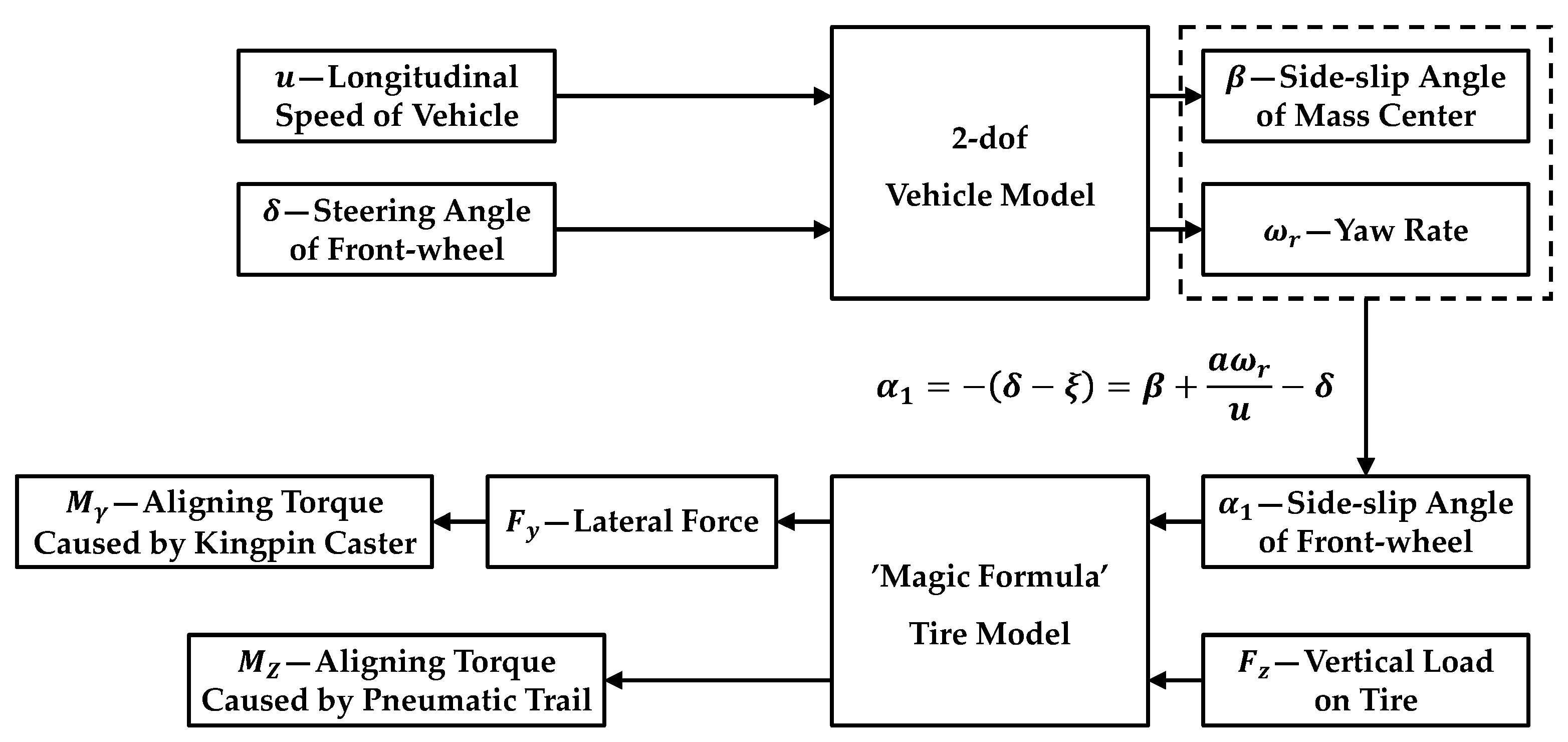
4. Modeling of Low-Speed Steering Resistance Torque Considering Tire/Pavement Friction
4.1. Low-Speed Steering Friction Torque between the Tire and Pavement
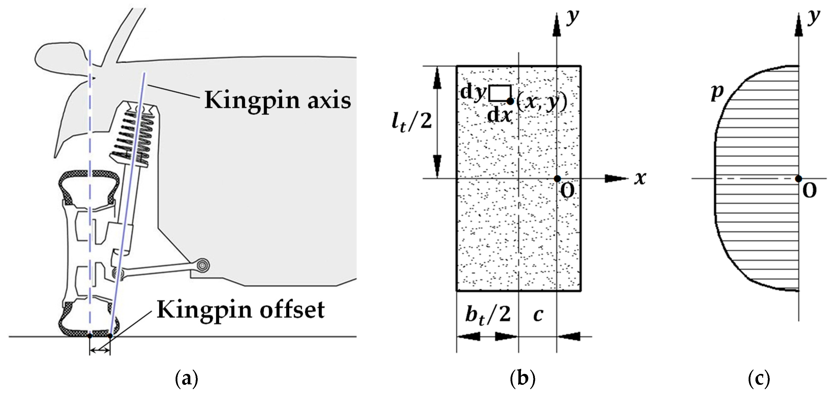
4.2. The Aligning Torque Caused by the Kingpin Inclination
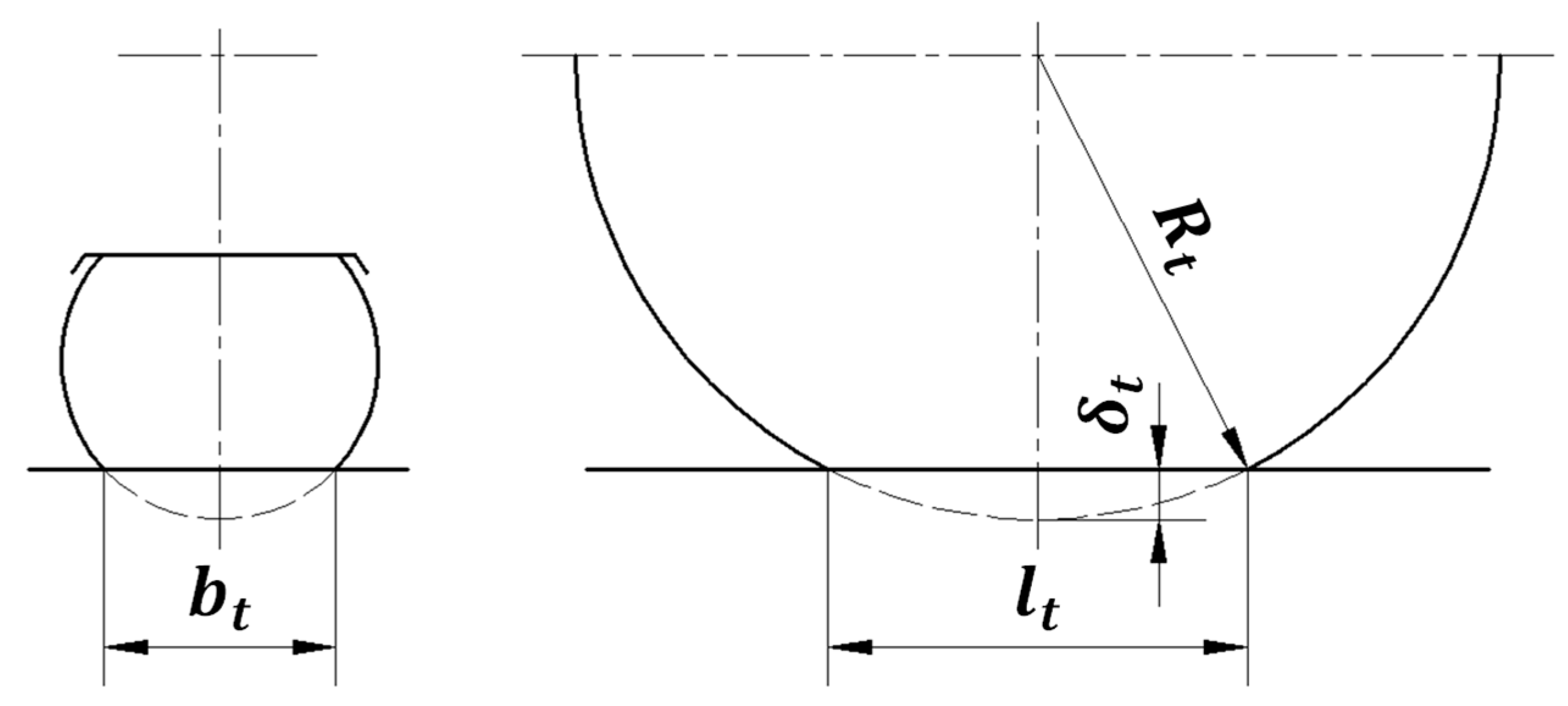
4.3. Aligning Torques Caused by the Kingpin Caster and Pneumatic Trail
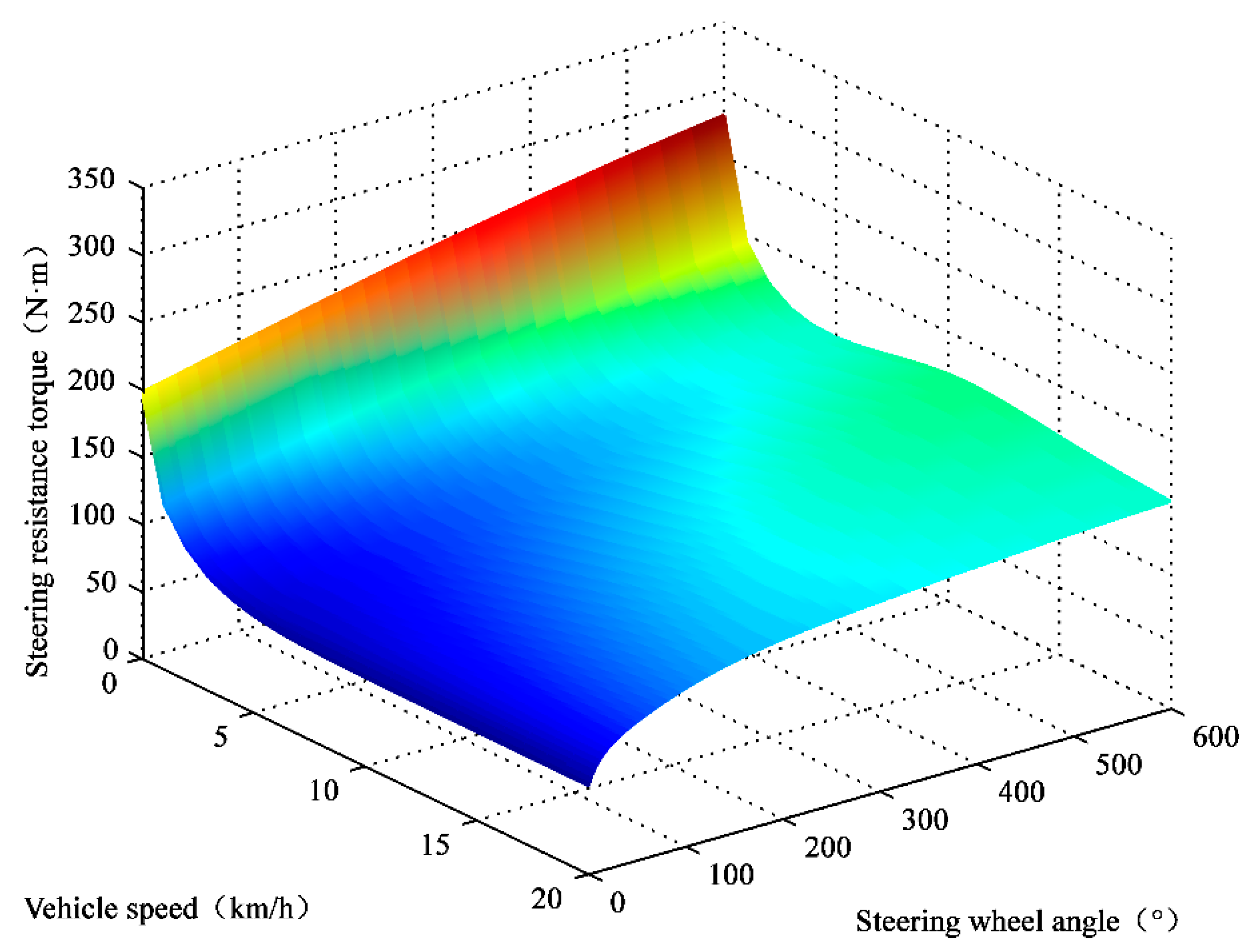
4.4. Model of the Low-Speed Steering Resistance Torque
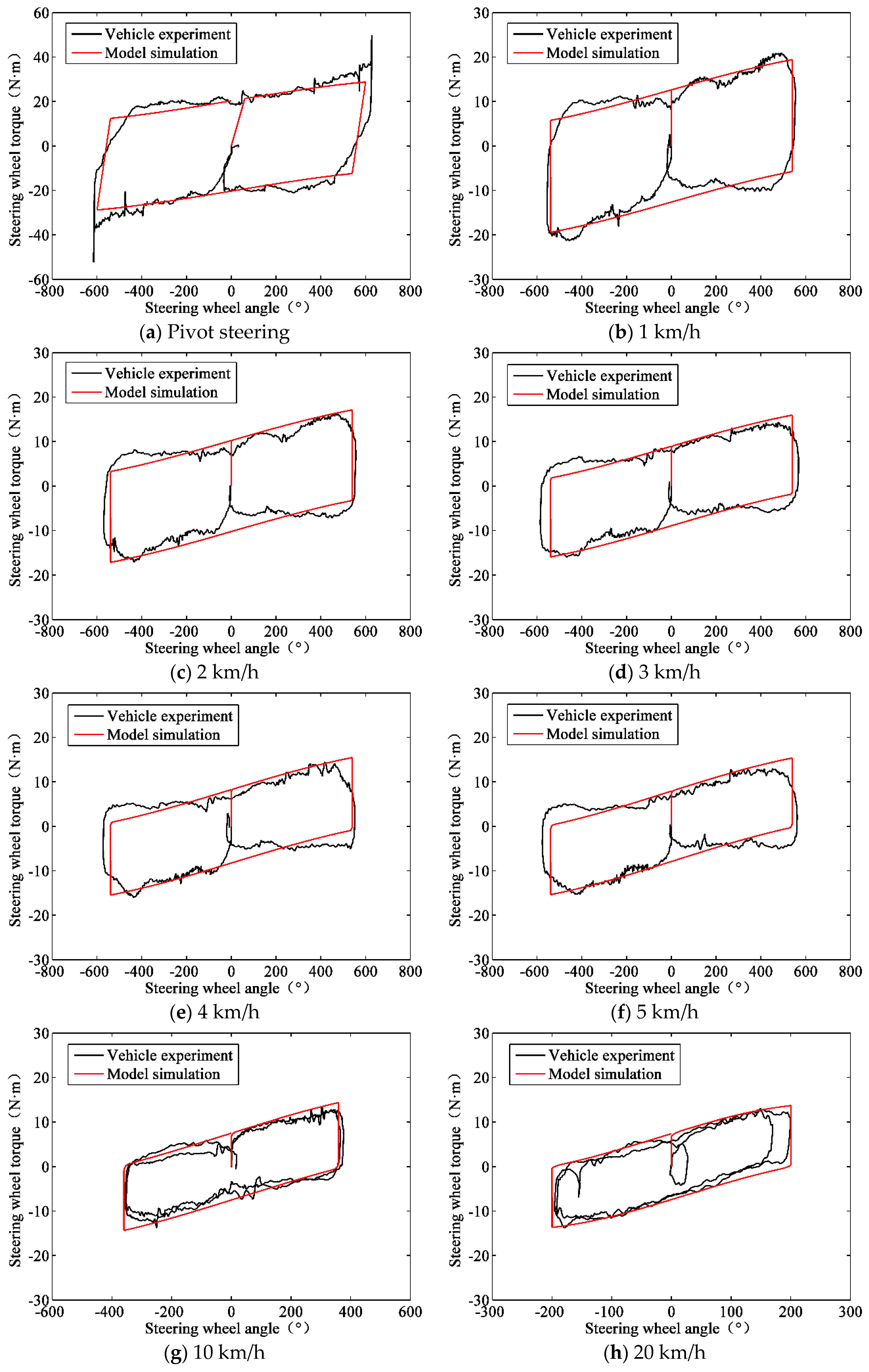
5. Model Simulation and Validation by Experiments
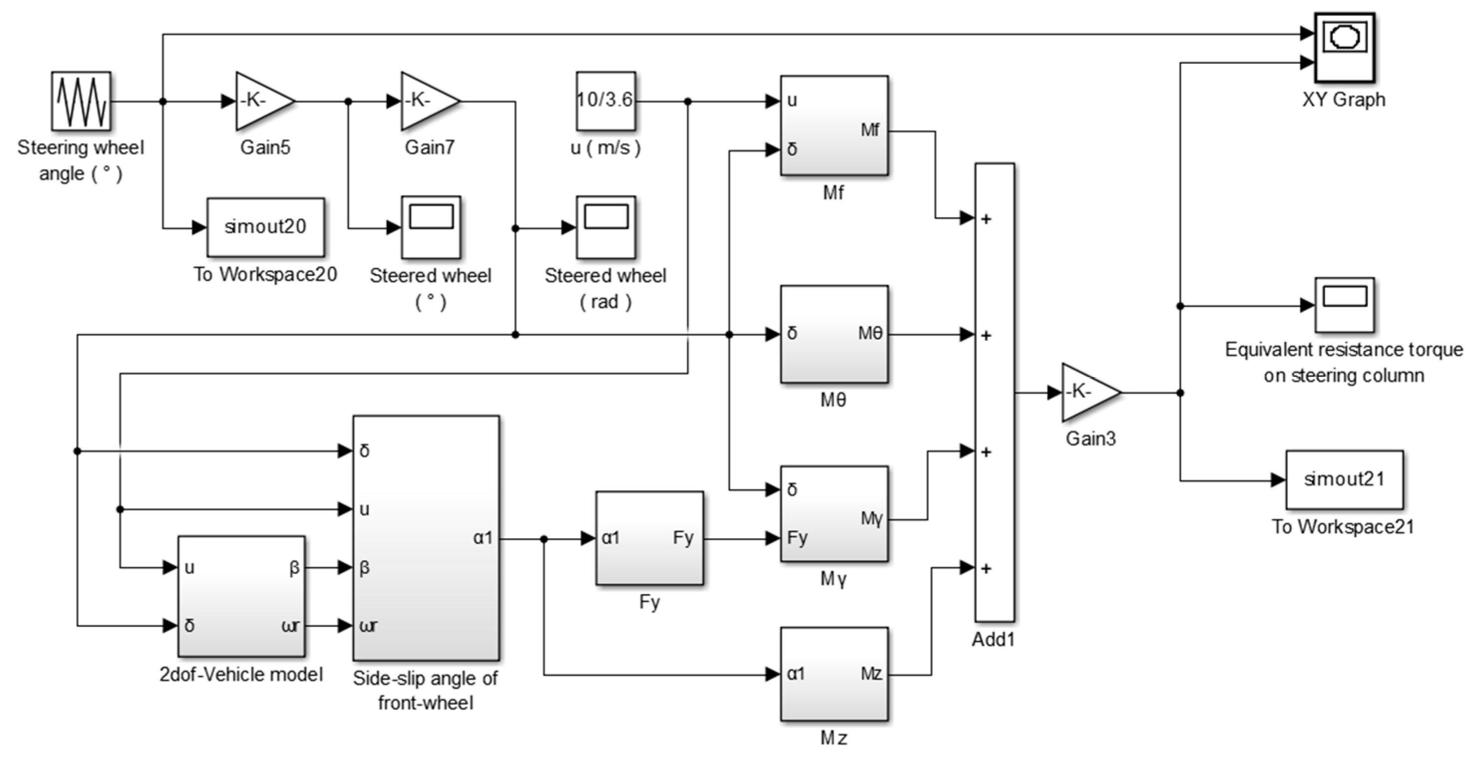
5.1. Model Simulation
5.2. Real Vehicle Experiments
5.3. Comparison of Simulation and Experiment Results
6. Conclusions
Author Contributions
Funding
Acknowledgments
Conflicts of Interest
References
- Tang, B.; Jiang, H.B.; Xu, Z.; Geng, G.; Xu, X. Dynamics of electromagnetic slip coupling for hydraulic power steering application and its energy-saving characteristics. J. Cent. South Univ. 2015, 22, 1994–2000. [Google Scholar] [CrossRef]
- Tang, B.; Jiang, H.B.; Gong, X.Q. Optimal design of variable assist characteristics of electronically controlled hydraulic power steering system based on simulated annealing particle swarm optimisation algorithm. Int. J. Veh. Des. 2017, 73, 189–207. [Google Scholar] [CrossRef]
- Hanifah, R.A.; Toha, S.F.; Ahmad, S.; Hassan, M.K. Swarm-Intelligence Tuned Current Reduction for Power-Assisted Steering Control in Electric Vehicles. IEEE Trans. Ind. Electron. 2018, 65, 7202–7210. [Google Scholar] [CrossRef] [Green Version]
- Du, P.P.; Su, H.; Tang, G.Y. Active Return-to-Center Control Based on Torque and Angle Sensors for Electric Power Steering Systems. Sensors. 2018, 18, 855. [Google Scholar] [Green Version]
- Zhao, W.Z.; Luan, Z.K.; Wang, C.Y. Parameter optimization design of vehicle E-HHPS system based on an improved MOPSO algorithm. Adv. Eng. Softw. 2018, 123, 51–61. [Google Scholar] [CrossRef]
- Ben Fathallah, M.A.; Ben Othman, A.; Besbes, M. Modeling a photovoltaic energy storage system based on super capacitor, simulation and evaluation of experimental performance. Appl. Phys. A Mater. Sci. Process. 2018, 124, 120. [Google Scholar] [CrossRef]
- Haubert, T.; Mindl, P.; Cerovsky, Z. Design of Control and Switching Frequency Optimization of DC/DC Power Converter for Super-capacitor. Automatika 2016, 57, 141–149. [Google Scholar] [CrossRef] [Green Version]
- Farhadi, M.; Mohammed, O.A. Event-Based Protection Scheme for a Multiterminal Hybrid DC Power System. IEEE Trans. Smart Grid 2015, 6, 1658–1669. [Google Scholar] [CrossRef]
- Jin, Y.; LU, Y.; Gong, J.H.; Lu, Z.; Li, W.; Wu, J. Design and Experiment of Electronic-hydraulic Loading Test-bed Based on Tractor’s Hydraulic Steering By-wire. Asian Agric. Res. 2015, 7, 86–89. [Google Scholar]
- Shiiba, T.; Murata, W. Experimental validation of steering torque feedback simulator through vehicle running test. J. Mech. Sci. Technol. 2009, 23, 954–959. [Google Scholar] [CrossRef]
- Karimi, D.; Mann, D. Torque feedback on the steering wheel of agricultural vehicles. Comput. Electron. Agric. 2009, 65, 77–84. [Google Scholar] [CrossRef]
- Park, W.; Ho, L.C.; Lee, S.; Ssung, L.K. The Effect of Ground Condition, Tire Inflation Pressure and Axle Load on Steering Torque. J. Biosyst. Eng. 2004, 29, 419–424. [Google Scholar] [CrossRef] [Green Version]
- Jiang, H.B. Variable Assist Characteristics and Control Strategies for ECHPS in Terms of Maneuverability and Energy Efficiency. J. Mech. Eng. 2015, 51, 88–97. [Google Scholar] [CrossRef]
- Sharp, R.S.; Granger, R. On car steering torques at parking speeds. Proc. Inst. Mech. Eng. Part D-J. Autom. Eng. 2003, 217, 87–96. [Google Scholar] [CrossRef] [Green Version]
- Wang, Y.C.; Gao, X.H.; Zhang, X.J. Static steering resisting moment of tire for heavy multi-axle steering vehicle. Trans. Chin. Soc. Agric. Eng. 2010, 26, 146–150. [Google Scholar]
- Wang, Y.C.; Feng, P.F.; Pang, W.J.; Zhou, M. Pivot steering resistance torque based on tire torsion deformation. J. Terramech. 2014, 52, 47–55. [Google Scholar]
- Zhuang, Y.; Guo, K.H. Tire Spot Turn Model Based on LuGre Model. Autom. Technol. 2008, 7, 1–2. [Google Scholar]
- Zhao, Y.X. The Research of Steering Characteristic Based on Steering Resistance Torque. Master’s Thesis, Chongqing University of Technology, Chongqing, China, June 2013. [Google Scholar]
- Ma, B.; Yang, Y.Y.; Liu, Y.H.; Ji, X.; Zheng, H. Analysis of vehicle static steering torque based on tire-road contact patch sliding model and variable transmission ratio. Adv. Mech. Eng. 2016, 8, 1–11. [Google Scholar] [CrossRef]
- Tamakawa, S.; Tanabe, H.; Mouri, H. Relationship between steering torque and ease of driving with bar type steering in high speed range. J. Adv. Mech. Des. Syst. Manuf. 2017, 11. [Google Scholar] [CrossRef] [Green Version]
- Kim, S.H.; Chu, C.N. A new manual Steering torque estimation model for steer-by-wire systems. Proc. Inst. Mech. Eng. Part D-J. Autom. Eng. 2016, 230, 993–1008. [Google Scholar] [CrossRef]
- Hayama, R.; Kawahara, S.; Nakano, S.; Kumamoto, H. Resistance torque control for steer-by-wire system to improve human-machine interface. Veh. Syst. Dyn. 2010, 48, 1065–1075. [Google Scholar] [CrossRef]
- Liu, Z.; Yang, J.J.; Liao, D.X. Effects of Vehicle Speed on Steering Torque. China Mech. Eng. 2005, 16, 748–751. [Google Scholar]
- Kim, S.H.; Chu, C.N. Hardware-in-the-loop simulations of an electrohydraulic power steering system for developing the motor speed map of heavy commercial vehicles. Proc. Inst. Mech. Eng. Part D J. Autom. Eng. 2015, 229, 1717–1731. [Google Scholar] [CrossRef]
- Wei, Y.T.; Oertel, C.; Liu, Y.H.; Li, X. A theoretical model of speed-dependent steering torque for rolling tyres. Veh. Syst. Dyn. 2016, 54, 463–473. [Google Scholar] [CrossRef]
- Tang, T.; Johnson, D.; Smith, R.E.; Felicellia, S.D. Numerical evaluation of the temperature field of steady-state rolling tires. Eng. Fail. Anal. 2014, 38, 1622–1637. [Google Scholar] [CrossRef]
- Li, Y.; Liu, W.Y.; Frimpong, S. Effect of ambient temperature on stress, deformation and temperature of dump truck tire. Mater. Des. 2012, 23, 55–62. [Google Scholar] [CrossRef]
- Zhuang, J.D. Vehicle Tire Science, 1st ed.; Beijing Institute of Technology Press: Beijing, China, 1996; pp. 200–209. ISBN 7-81045-067-0. [Google Scholar]
- Zhuang, J.D. Calculation of Vehicle Terramechanics, 1st ed.; China Machine Press: Beijing, China, 2002; pp. 52–60. ISBN 7-111-09417-4. [Google Scholar]
- Chen, S.A.; Qiu, F.; He, R.; Lu, S. Analysis of Self-aligning Torque from Vehicle Kingpin Inclination. Trans. Chin. Soc. Agric. Mach. 2008, 39, 32–35. [Google Scholar]
- Jiang, Z.Z.; Xiao, B.X. LQR optimal control research for four-wheel steering forklift based-on state feedback. J. Mech. Sci. Technol. 2018, 32, 2789–2801. [Google Scholar] [CrossRef]
- Tang, B.; Jiang, H.B.; Chen, L.; Geng, G.; Yao, J. Steering Stability Control of Vehicles Equipped with E-ECHPS Based on Differential Geometry. Trans. Chin. Soc. Agric. Mach. 2015, 46, 285–293. [Google Scholar]
- Shi, P.C.; Zhao, Q.; Zhang, R.Y.; Li, Y. The Simulation of Tire Dynamic Performance Based on “Magic Formula”. In Proceedings of the 2017 2nd International Conference on Automation, Mechanical Control and Computational Engineering (AMCCE 2017), Beijing, China, 25–26 March 2017; pp. 699–703. [Google Scholar]


| Part | Elasticity Modulus (MPa) | Poisson’s Ratio | Density (g/cm3) | Mooney Coefficients (MPa) | |
|---|---|---|---|---|---|
| Tread | —— | —— | 1.14 | 2.0477 | 1.1859 |
| Carcass | 794 | 0.45 | 1.39 | —— | —— |
| Belt | 55,000 | 0.3 | 7.64 | —— | —— |
| Pavement | 1400 | 0.35 | 2.4 | —— | —— |
| Running Speed (km/h) | 1 | 2 | 4 | 6 | 8 | 10 |
|---|---|---|---|---|---|---|
| Steering friction force (N) | 1504.52 | 1230.89 | 997.21 | 847.82 | 741.94 | 660.39 |
| Equivalent friction coefficient | 0.5015 | 0.4103 | 0.3324 | 0.2826 | 0.2473 | 0.2201 |
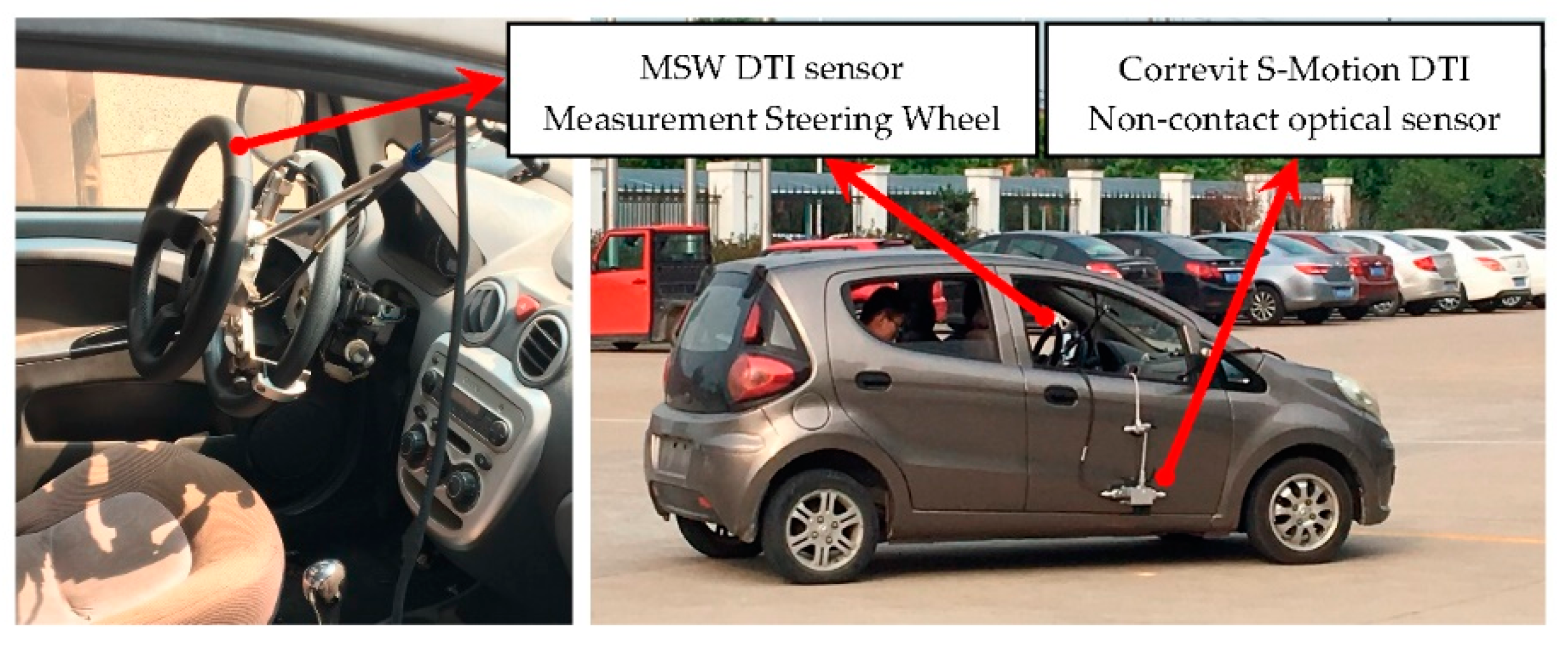
| Apparatus | Application | Type | Manufacturer |
|---|---|---|---|
| MSW DTI sensor Universal measurement steering wheel | Universal measurement steering wheel for measurement of the steering torque, steering angle and steering speed; for vehicle driving dynamics tests like ISO 4138, steady-state circular course drive. | 5612A | KISTLER |
| Correvit S-Motion DTI Non-contact optical sensor | High-precision, slip-free measurement of:
| 2055A | KISTLER |
© 2019 by the authors. Licensee MDPI, Basel, Switzerland. This article is an open access article distributed under the terms and conditions of the Creative Commons Attribution (CC BY) license (http://creativecommons.org/licenses/by/4.0/).
Share and Cite
Cao, D.; Tang, B.; Jiang, H.; Yin, C.; Zhang, D.; Huang, Y. Study on Low-Speed Steering Resistance Torque of Vehicles Considering Friction between Tire and Pavement. Appl. Sci. 2019, 9, 1015. https://doi.org/10.3390/app9051015
Cao D, Tang B, Jiang H, Yin C, Zhang D, Huang Y. Study on Low-Speed Steering Resistance Torque of Vehicles Considering Friction between Tire and Pavement. Applied Sciences. 2019; 9(5):1015. https://doi.org/10.3390/app9051015
Chicago/Turabian StyleCao, Dong, Bin Tang, Haobin Jiang, Chenhui Yin, Di Zhang, and Yingqiu Huang. 2019. "Study on Low-Speed Steering Resistance Torque of Vehicles Considering Friction between Tire and Pavement" Applied Sciences 9, no. 5: 1015. https://doi.org/10.3390/app9051015
APA StyleCao, D., Tang, B., Jiang, H., Yin, C., Zhang, D., & Huang, Y. (2019). Study on Low-Speed Steering Resistance Torque of Vehicles Considering Friction between Tire and Pavement. Applied Sciences, 9(5), 1015. https://doi.org/10.3390/app9051015