Article

Dynamic Phase Measuring Profilometry Based on Tricolor Binary Fringe Encoding Combined Time-Division Multiplexing

Department of Opto-electronics, Sichuan University, Chengdu 610064, China
*
Author to whom correspondence should be addressed.
Appl. Sci. 2019, 9(4), 813; https://doi.org/10.3390/app9040813
Submission received: 4 January 2019 / Revised: 5 February 2019 / Accepted: 16 February 2019 / Published: 25 February 2019
(This article belongs to the Special Issue High-speed Optical 3D Shape and Deformation Measurement)

Abstract

:
A dynamic phase measuring profilometry (PMP) based on tricolor binary fringe combined time-division multiplexing principle is proposed. Only one tricolor binary fringe combined by red (R), green (G), and blue (B) binary fringes with the same fringe width but without any color overlapping one another is needed and sent into the flash memory of a high-speed digital light projector (HDLP) in advance. A specialized time-division multiplexing timing sequence is designed to control the HDLP to project the tricolor binary fringe saved in the flash memory onto the measured dynamic object separately and sequentially at 234 fps, at the same time, the projected light source mode is set as monochrome mode which means that all the RGB LEDs remain lighting. Meanwhile, it also triggers a high frame rate monochrome camera synchronized with the HDLP to capture the corresponding deformed patterns in R, G and B channels. By filtering, the nearly unbroken phase-shifting sinusoidal deformed patterns for three-step PMP can be extracted from the captured deformed patterns. It is equivalent to the three-dimensional (3D) shape reconstruction of the measured dynamic object at 78 fps. Experimental results verify the feasibility and the validity of the proposed method. It is effective for measuring the dynamic object and can avoid the color cross-talk effectively.

1. Introduction

Optical three dimensional (3D) shape measurement based on fringe projection is widely used in many fields such as industry inspection [1], 3D thermal deformation measurement of electronic devices [2], 3D point cloud reconstruction [3], 3D printing [4], face recognition [5] and so on with its advantages of noncontacting measurement, full-field acquisition, high precision, and ease of information processing. The traditional static or online 3D shape measurement methods based on fringe projection may be hard to satisfy the demand of real-time or dynamic 3D shape measurement. With the rapid development of digital light projector (DLP) devices, digital imaging acquisition devices, and personal computers [6,7], many dynamic 3D shape measurement techniques have been proposed.
The existed methods for dynamic 3D shape measurement mainly contain Fourier transform profilometry (FTP) [8,9], single-one color fringe projection profilometry [10], and multiple fringes phase measuring profilometry (PMP) based on high-speed projection system [11,12]. The FTP proposed by Takeda et al. [13] can achieve dynamic 3D measurement [14] because it can reconstruct 3D shape from one deformed pattern, but its measuring accuracy is probably limited due to the filtering procedure. In order to improve the measuring accuracy, the single-one color fringe projection profilometry [15] becomes an effective method. When a color sinusoidal fringe whose red (R), green (G), and blue (B) components comprise three sinusoidal fringes with an equivalent shifting-phase of 2π/3 is projected onto the measured object [16], the corresponding color deformed pattern modulated by the profile of the measured object can be captured by a color charge coupled device (CCD) camera. The corresponding phase-shifting deformed patterns can be retrieved simply from the R, G, and B components of the captured color deformed pattern. So the 3D shape of the measured object can be reconstructed successfully with three-step PMP. However, the color cross-talk and the grayscale imbalance problems caused by the color overlapping among the R, G, and B channels one another may lead to extracting the phase-shifting deformed patterns incompletely [17]. Thus, some corresponding color decoupling compensation and grayscale imbalance correction methods are proposed [18,19,20,21]. Cao et al. proposed an improved RGB tricolor based fast phase measuring profilometry in which the chroma transfer function (CTF) was introduced to correct the color cross-talk and grayscale imbalance problems among R, G, and B channels [22]. This method can reduce the effect of these problems and improve the measuring accuracy, but it may be hard to avoid these problems completely and needs additional calibration experiments. Pan et al. proposed software-based and hardware-based methods to compensate for the color coupling and grayscale imbalance errors by designing a three-CCD camera system and three color filters detect system [20]. It worked well, the measuring system may be complicated due to the additional multiple CCD cameras and color filters. Zou et al. proposed a color fringe-projected technique based on bidimensional empirical mode decomposition to decouple to color cross-talk among color channels [19]. It did reduce the errors caused by the color cross-talk, but its computational process may be complicated and time consuming. Although the above methods can reduce the effect of color cross-talk and grayscale imbalance problems existed in color CCD camera, these methods may be hard to solve the above problems completely and more time consuming.
In order to avoid the color cross-talk problem completely, the multiple fringes PMP based on high-speed projection system [23] is proposed to realize dynamic 3D shape measurement. This method mainly utilized the high-speed digital light projector (HDLP) to project the N frames of phase-shifting sinusoidal fringes onto the measured object at N times of dynamic frame rate. The corresponding phase-shifting deformed patterns can be captured by a synchronous high frame rate monochrome camera. So the 3D shape of the measured object can be reconstructed with N-step PMP. Zhang et al. used the single-chip DLP technology for projecting three coded sinusoidal fringes rapidly and sequentially to realize dynamic 3D shape measurement by removing the color filters onto the color wheel of the projector [24]: the color cross-talk problem can be avoided. However, the operation may be inconvenient because the DLP needed to be reinstalled. With the development of the DLP technology, Zhu and Ma et al. solved the color cross-talk problem by utilizing a special DLP substituted for the ordinary commercial DLP and a high frame rate monochrome camera substituted for the color CCD camera to realize dynamic 3D shape measurement [25,26]. Although the color cross-talk problem can be avoided completely, the grayscale imbalance caused by the monochrome camera’s different sensitivity to R, G, and B light was needed additional correction. Furthermore, the sinusoidal fringe projection speed of the DLP is limited to less than 120 frames per second (fps) due to the grayscale values of the sinusoidal fringe is from 0 to 255 [27]. In order to improve the projection speed of the DLP, the dynamic 3D measurement based on defocusing binary fringe projection [26] is proposed. The binary fringe refresh rate of the DLP can be reach tens of kHz by using the recently developed digital light processing discovery technology [28] due to the binary feature of the binary fringe. The sinusoidal fringe pattern can be approximated by properly defocusing the projected binary fringe [29]. However, the binary fringe defocusing projection method needs an additional defocusing device and its measurement range may be limited by the lesser depth of field caused by defocusing, it may be difficult to calibrating the defocused projector [30,31].
In order to solve the above problems, a dynamic phase measuring profilometry based on tricolor binary fringe encoding combined time-division multiplexing (TDM) principle is proposed.

2. The Tricolor Binary Fringe Encoding Principle

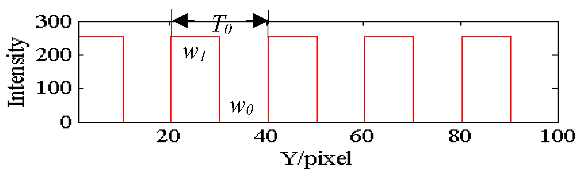
In the traditional phase measuring profilometry (PMP) based on binary fringe projection [32], the traditional binary fringe is shown in Figure 1. The width for non-zero transmittance ( w 1 ) of the binary fringe is always encoded the same as that for zero transmittance ( w 0 ) in one period ( T 0 ) as shown in Figure 1. The corresponding sinusoidal fringe pattern can be approximated by properly defocusing the binary fringe [29] or using the nonlinear error suppression of the large-step PMP based on binary fringe projection [30]. The duty cycle P d c can be expressed as
P d c = w 1 T 0
Until now, the duty cycle is always 1/2 used in PMP based on binary fringe projection. In the proposed method, this traditional barrier is broken through. A new duty cycle binary fringe is introduced that means P d c may not be 1/2 but 1/3, meaning that the w 1 can be smaller than w 0 in one period. It is found that although the duty cycle is not 1/2 in the encoded binary fringe, its fundamental frequency components of Fourier spectrum contains the sinusoidal fringe pattern information. Just by filtering operation in spatial frequency domain, the nearly unbroken sinusoidal fringe pattern can be extracted effectively.
The introduced binary fringe can be modeled as the convolution of the rectangular window function and the comb function. Its gray value g ( x , y ) can be expressed as
g ( x , y ) = A 0 r e c t ( y P d c T 0 ) * c o m b ( y T 0 )
where A 0 is a constant represented as the non-zero grayscale of the introduced binary fringe, * denotes the convolution operation. Its Fourier spectrum G ( f x , f y ) can be expressed as
G ( f x , f y ) = A 0 P d c T 0 j = j = sin c ( P d c T 0 f y ) δ ( f y j f 0 )
where f 0 = 1 / T 0 denotes the fundamental frequency of the Fourier spectrum. By introducing a proper rectangular window low-pass filter, the zero frequency component, the positive frequency component, and the negative frequency component G ( f x , f y ) can be retained as
G ( f x , f y ) = A 0 P d c T 0 { δ ( f y ) + sin c ( P d c ) [ δ ( f y + f 0 ) + δ ( f y f 0 ) ] }
By inverse Fourier transform for G ( f x , f y ) , the nearly unbroken sinusoidal fringe pattern g ( x , y ) can be extracted as
g ( x , y ) = A 0 P d c T 0 + 2 A 0 P d c T 0 sin c ( P d c ) cos ( 2 π y T 0 )
It can be simplified as the mathematic model of PMP [33] and expressed as:
g ( x , y ) = A ( x , y ) + B ( x , y ) cos ( 2 π y T 0 )
where A 0 P d c T 0 , simplified as A ( x , y ) , represents the background light intensity, and 2 A 0 P d c T 0 sin c ( P d c ) , simplified as B ( x , y ) , reflects the contrast of the fringe pattern.
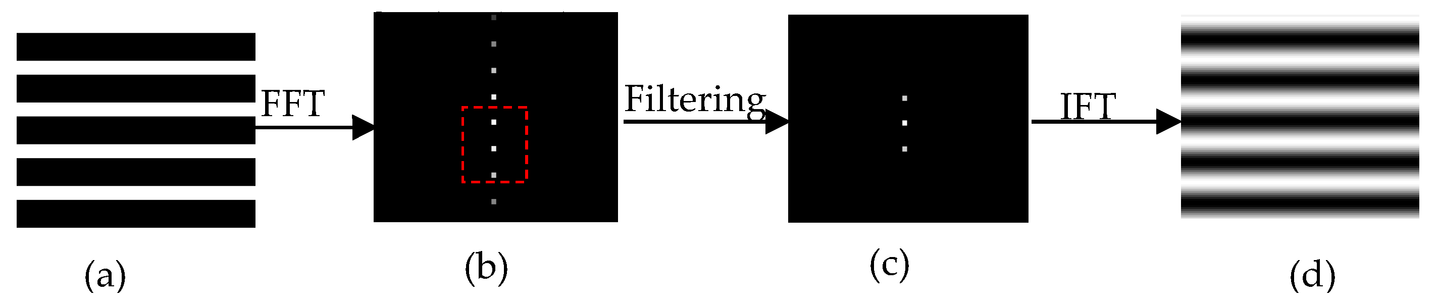
The corresponding sinusoidal fringe pattern extracting process is show in Figure 2. When the encoded binary fringe is projected onto the reference by the HDLP, the fringe pattern is captured by a high frame rate complementary metal oxide semiconductor (CMOS) monochrome camera, as shown in Figure 2a. By fast Fourier transform (FFT), its Fourier spectrum is shown in Figure 2b, it can be seen that although there many higher order harmonic frequencies existed in the frequency domain, the Fourier spectrum distribution is discrete. By introducing a proper rectangular window low-pass filter, the frequency components contained the sinusoidal fringe pattern information as shown in the dotted box in Figure 2b can be retained as shown in Figure 2c. By inverse Fourier transform (IFT), the nearly unbroken sinusoidal fringe pattern (see Figure 2d) can be extracted efficiently. In the same way, the nearly unbroken sinusoidal deformed pattern also can be extracted from the captured deformed pattern when the encoded binary fringe is projected onto the measured object.
Furthermore, the effects of the traditional binary fringe, and the introduced binary fringe on their Fourier spectrums, are analyzed. At the same time, the amplitudes of the Fourier spectrums in binary fringes are also analyzed, from Equation (4), the amplitude A max ( f 0 , P d c ) of the fundamental frequency spectrum in binary fringe can be expressed as
A max ( f 0 , P d c ) = A 0 P d c T 0 sin c ( P d c )
The traditional 1/2 duty cycle binary fringe and the 1/3 duty cycle binary fringe as shown in Figure 3a,b, respectively, are taken as an example. In this example, their image sizes are all 300 pixels × 300 pixels. By FFT for them, their corresponding Fourier spectrums are shown in Figure 3c,d, respectively; it can be seen that the second order harmonic frequency spectrum vanishes in the traditional binary fringe but exists in the 1/3 duty cycle binary fringe. Although the second order harmonic frequency spectrum exists in the 1/3 duty cycle binary fringe, its proportion is small enough. It means that the shape reconstruction error caused by the second order harmonic frequency spectrum is small enough. According to Equation (7), it can also be seen that the amplitude of the fundamental frequency spectrum in traditional binary fringe is 4700 and that of the 1/3 duty cycle binary fringe is 4000 from Figure 3c,d. But if the zero frequency spectrums and the fundamental frequency spectrums in Figure 3c,d are filtered out respectively by introducing a proper rectangular window low-pass filter as shown in the rectangle box in Figure 3c,d with the above-mentioned process, it can be seen that these retained frequency spectrum components’ distributions contained the sinusoidal fringe information are similar. Then they aligned the same amplitude of the fundamental frequency spectrum by simply multiplying the latter spectrum with 4700/4000, it is found that the aligned frequency spectrums are very similar to those shown in Figure 3e. It reveals that the 1/3 duty cycle binary fringe has the same effect as the traditional binary fringe. By IFT for the aligned frequency spectrums in Figure 3e respectively, the corresponding nearly unbroken sinusoidal fringe patterns can be efficiently extracted from the traditional binary fringe and the 1/3 duty cycle binary fringe respectively. Figure 3f show the cutaway views of the extracted sinusoidal fringe patterns in one columns, it can be seen that the transmittance function of the sinusoidal fringe pattern extracted from the 1/3 duty cycle binary fringe is much close to that of the traditional binary fringe. Furthermore, it also reveals that the reconstructed phase information of the measured object by using the 1/3 duty cycle binary fringe can be close to that of traditional binary fringe.
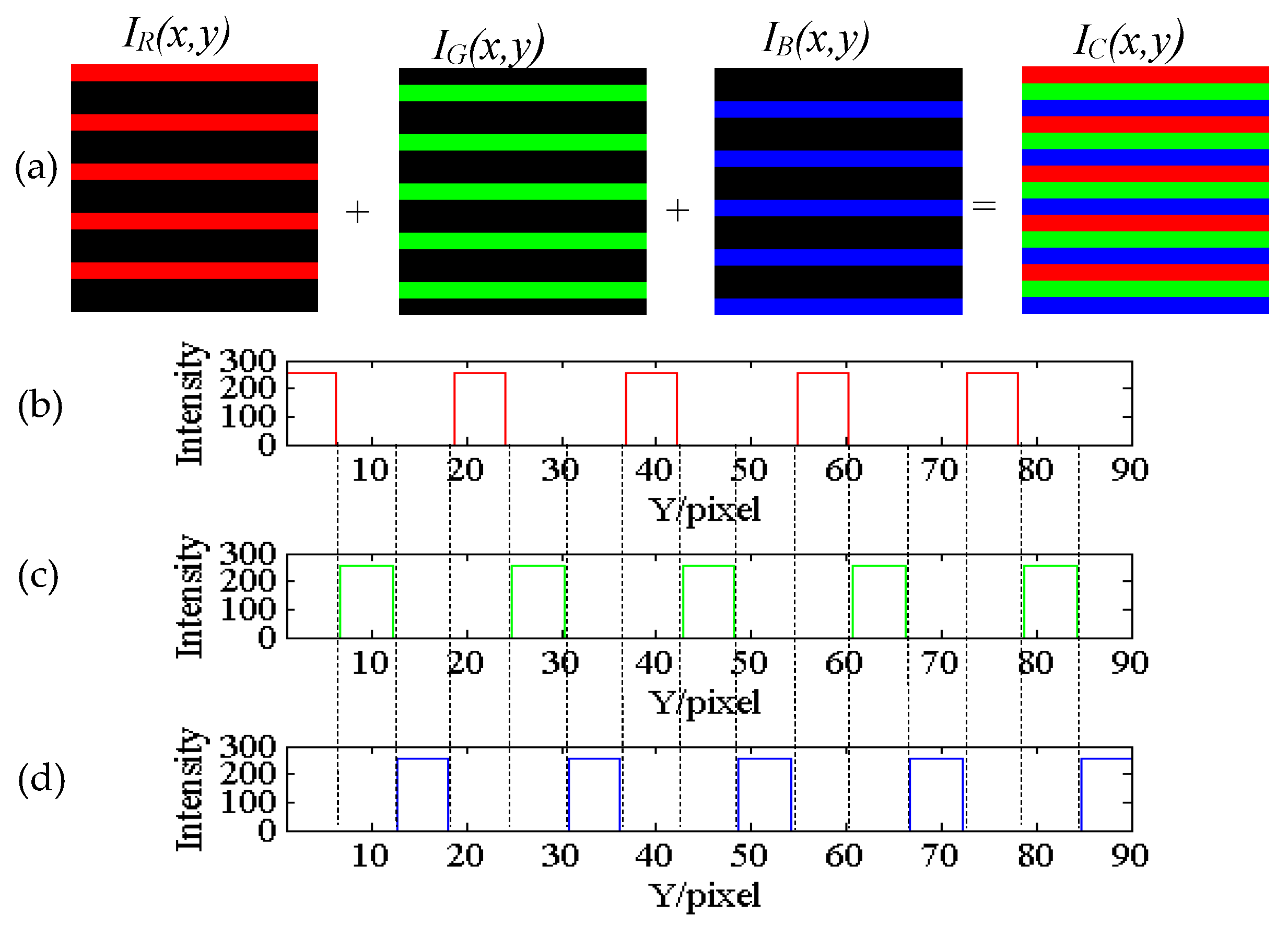
In order to realize dynamic 3D shape measurement with the introduced binary fringe, a tricolor binary fringe is designed as shown in Figure 4a in which its R, G, and B components are encoded by three monochromatic binary fringes with the same duty cycle of 1/3 but shifted 1/3 period one by one. It can be seen that R, G and B components of the encoded tricolor binary fringe share the same fringe width of 1/3 periods and are independent without any color overlapping in the non-zero regions one by one as shown in Figure 4b–d, so the encoded tricolor binary fringe can avoid the color overlapping problem in the traditional composite color sinusoidal fringe. The mathematic model of the tricolor binary fringe I C ( x , y ) can be expressed as
I C ( x , y ) = I R ( x , y ) R + I G ( x , y ) G + I B ( x , y ) B
where I R ( x , y ) , I G ( x , y ) , and I B ( x , y ) denote the grayscale distributions of the R, G, and B components in the tricolor binary fringe:
{ I R ( x , y ) = A 0 r e c t ( y P d c T 0 ) * c o m b ( y T 0 ) I G ( x , y ) = A 0 r e c t ( y P d c T 0 ) * c o m b ( y T 0 / 3 T 0 ) I B ( x , y ) = A 0 r e c t ( y P d c T 0 ) * c o m b ( y 2 T 0 / 3 T 0 )

3. The Dynamic PMP Principle Based on the Tricolor Binary Fringe

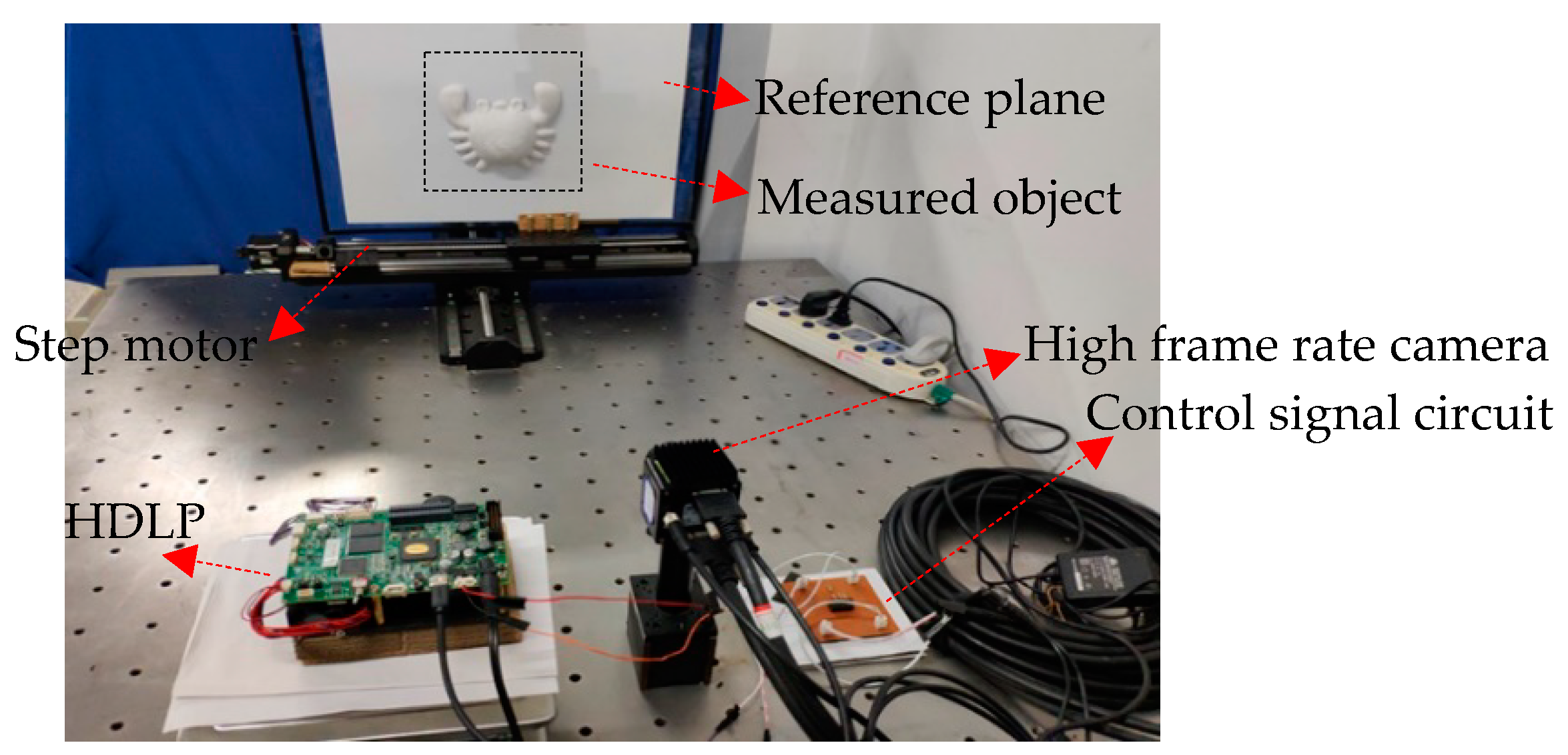
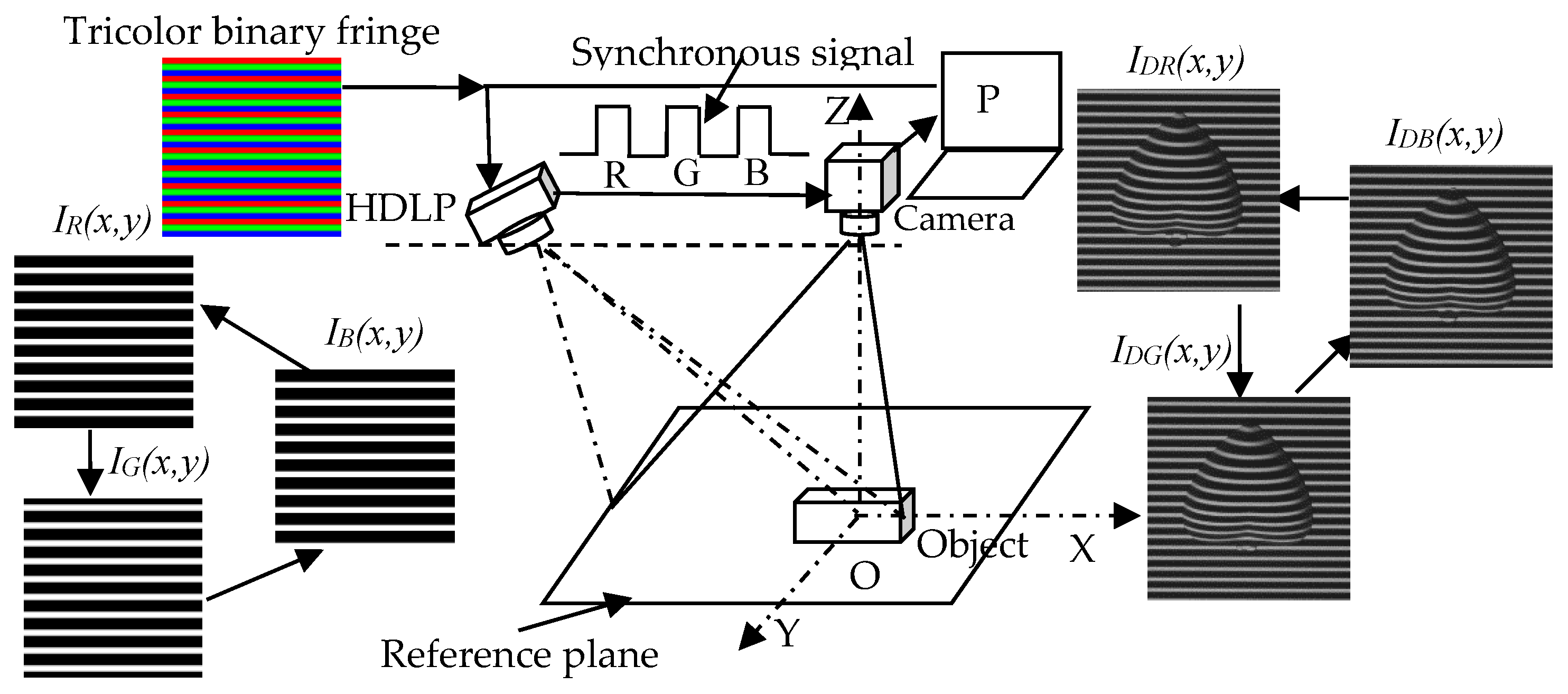
The schematic diagram of the dynamic PMP principle based on the proposed tricolor binary fringe is shown in Figure 5. Before measuring, the proposed tricolor binary fringe is encoded and saved into the flash memory of the HDLP in advance. Under the control of a special time-division multiplexing (TMD) timing sequence, the HDLP projects the encoded tricolor binary fringe saved in the flash memory with its R, G, and B channels ( I R ( x , y ) , I G ( x , y ) , and I B ( x , y ) 
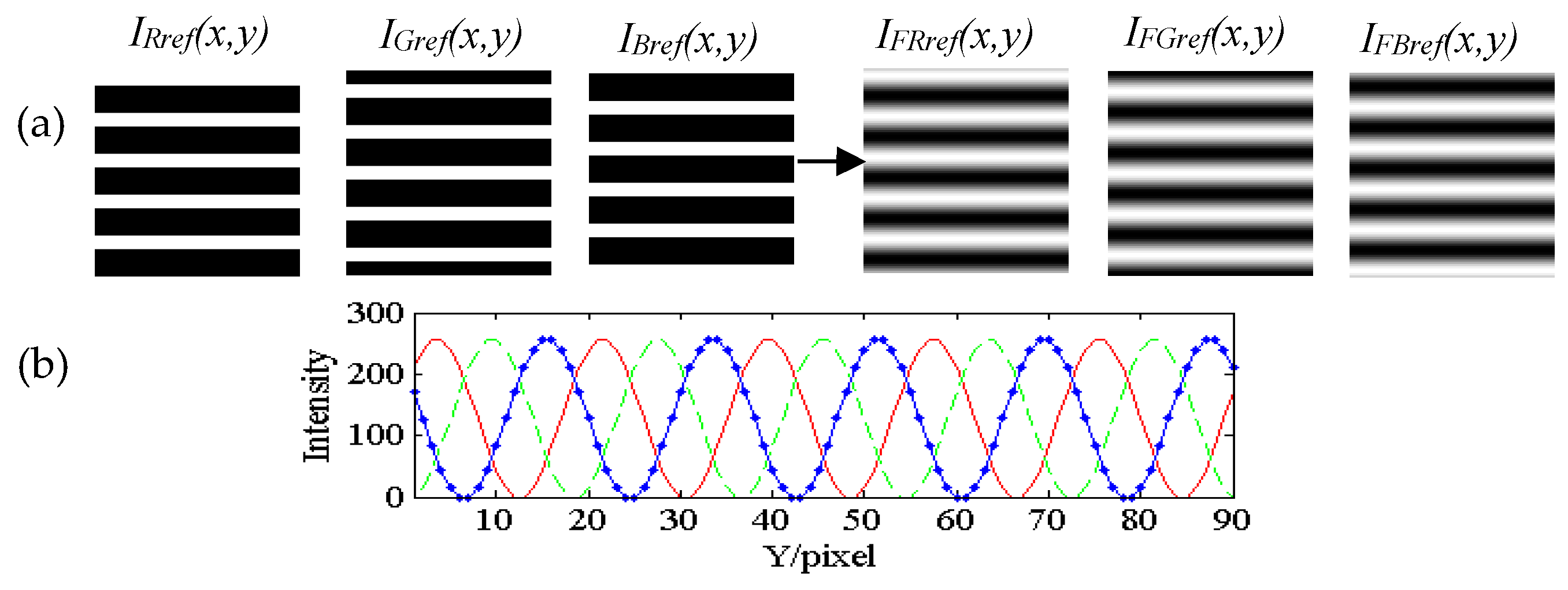
) onto the reference plane separately and sequentially. At the same time, the projected light source mode was set as monochrome mode which means that all the RGB LEDs remain lighting mode, so that every frame binary fringe could be projected as a grayscale fringe, effectively avoiding the grayscale imbalance problem caused by the monochrome camera’s different sensitivity to the R, G, and B light. Meanwhile, a high frame rate monochrome CMOS camera synchronized with the HDLP was used to capture the corresponding three fringe patterns I R r e f ( x , y ) , I G r e f ( x , y ) , and I B r e f ( x , y ) from R, G, and B channels, as shown in Figure 6a. The filtering operation is as discussed in Section 2, the corresponding extracted three nearly unbroken sinusoidal fringe patterns— I F R r e f ( x , y ) , I F G r e f ( x , y ) , and I F B r e f ( x , y ) —can be obtained as shown in Figure 6a. Their cutaway views of the three extracted sinusoidal fringe patterns are shown in Figure 6b, it can be seen that the three extracted sinusoidal fringe patterns have an equivalent shifting-phase of 2π/3 one another. According to the calculation process of Equations (2)–(6), they can be expressed as
{ I F R r e f ( x , y ) = A ( x , y ) + B ( x , y ) cos [ 2 π y T + φ 0 ( x , y ) ] I F G r e f ( x , y ) = A ( x , y ) + B ( x , y ) cos [ 2 π y T + φ 0 ( x , y ) + 2 π 3 ] I F B r e f ( x , y ) = A ( x , y ) + B ( x , y ) cos [ 2 π y T + φ 0 ( x , y ) + 4 π 3 ]
where T denotes the period of the captured fringe pattern. φ 0 ( x , y ) denotes the phase caused by the reference plane, it can be expressed as
φ 0 ( x , y ) = arctan [ 3 ( I F R r e f ( x , y ) I F B r e f ( x , y ) ) 2 I F G r e f ( x , y ) I F R r e f ( x , y ) I F B r e f ( x , y ) ]
As φ 0 ( x , y ) is wrapped in ( π , π ] due to the arctan function it should be unwrapped to be Φ 0 ( x , y ) by a phase unwrapping algorithm [34] and saved in the computer in advance.
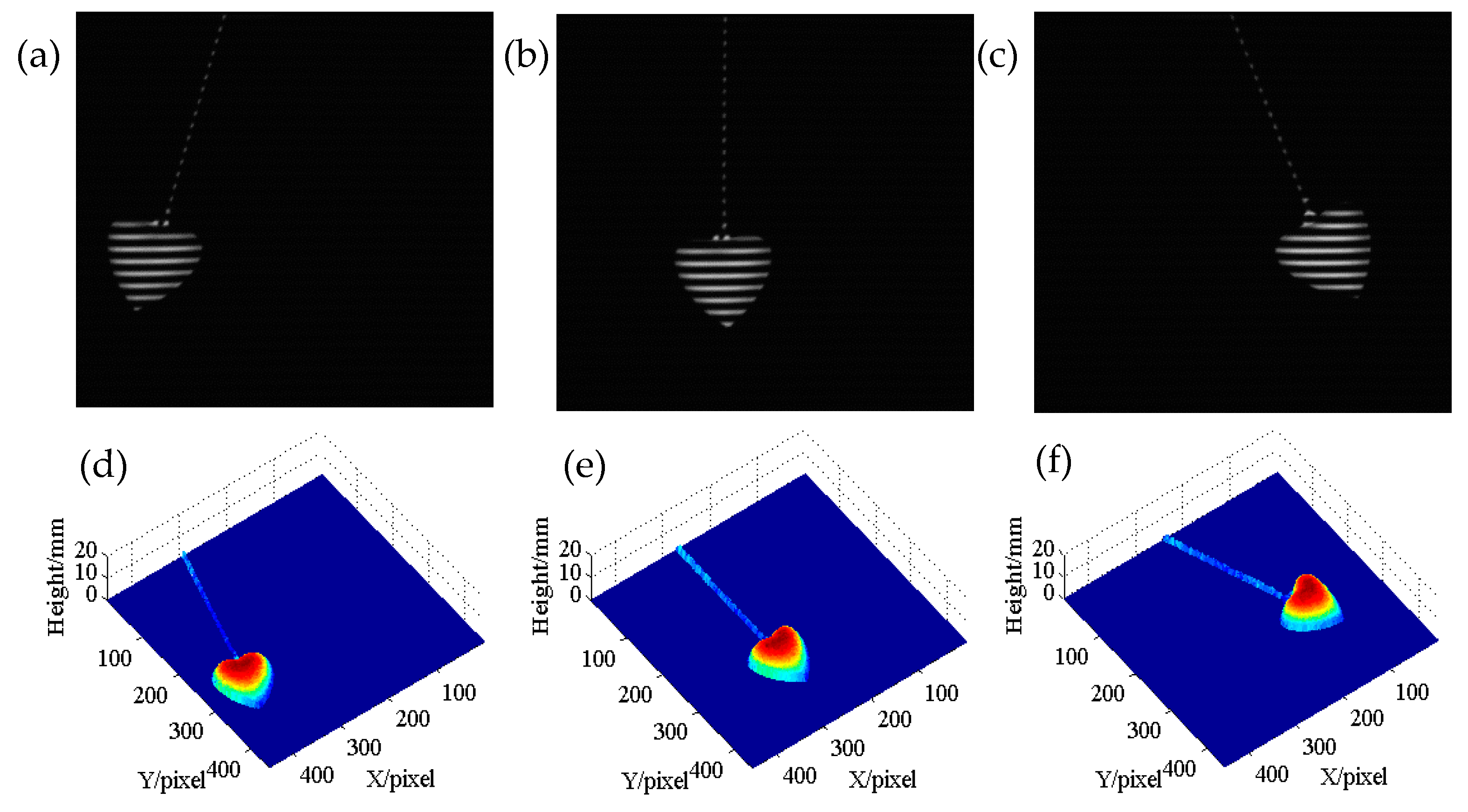
While measuring, under the same condition above-mentioned, the HDLP projects the encoded tricolor binary fringe in R, G, and B channels ( I R ( x , y ) , I G ( x , y ) , and I B ( x , y ) ) onto the measured object separately and sequentially at three times of dynamic frame rate, the corresponding three deformed patterns ( I D R ( x , y ) , I D G ( x , y ) , and I D B ( x , y ) ) from R, G, and B channels can be captured by the high frame rate CMOS monochrome camera synchronized with the HDLP as shown in Figure 5. In the same way as discussed in Section 2, the captured three deformed patterns— I D R ( x , y ) , I D G ( x , y ) , and I D B ( x , y ) —which were processed the corresponding extracted nearly unbroken sinusoidal deformed patterns I F D R ( x , y ) , I F D G ( x , y ) , and I F D B ( x , y ) can be expressed as
{ I F D R ( x , y ) = A ( x , y ) + B ( x , y ) cos [ 2 π y T + φ ( x , y ) ] I F D G ( x , y ) = A ( x , y ) + B ( x , y ) cos [ 2 π y T + φ ( x , y ) + 2 π 3 ] I F D B ( x , y ) = A ( x , y ) + B ( x , y ) cos [ 2 π y T + φ ( x , y ) + 4 π 3 ]
where φ ( x , y ) is the phase modulated by the measured object located the reference plane; it can also be expressed as
φ ( x , y ) = arctan [ 3 ( I F D R ( x , y ) I F D B ( x , y ) ) 2 I F D G ( x , y ) I F D R ( x , y ) I F D B ( x , y ) ]
It also should be unwrapped to Φ ( x , y ) . The phase Ψ ( x , y ) , which s modulated by the height of the measured object, is the difference Φ ( x , y ) and Φ 0 ( x , y ) . Ψ ( x , y ) can be expressed as
Ψ ( x , y ) = Φ ( x , y ) Φ 0 ( x , y )
So the 3D shape of the measured object is reconstructed by phase-to-height mapping relationship [35] as
1 h ( x , y ) = a ( x , y ) + b ( x , y ) 1 Ψ ( x , y ) + c ( x , y ) 1 Ψ 2 ( x , y )
where the system constants a ( x , y ) , b ( x , y ) , and c ( x , y ) can be calibrated by several planes with known heights. Furthermore, due to the phase of the binary fringe will be slightly changed during the FFT process, it may introduce a phase error. However, this phase error is the system phase error, it can be eliminated by the three-step PMP algorithm used in the proposed method.
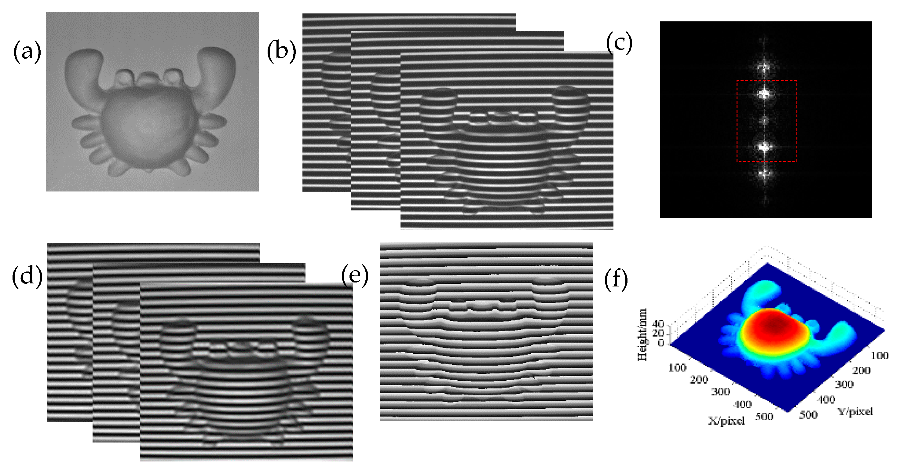
The corresponding reconstruction process of the proposed method is shown in Figure 7. The captured three deformed patterns, I D R ( x , y ) , I D G ( x , y ) , and I D B ( x , y ) , from R, G, and B channels were processed as outlined in the above-mentioned process. By FFT, their Fourier spectrums (R spectrum, G spectrum, and B spectrum) are shown in Figure 7. After proper filtering, their zero frequency components and the fundamental frequency components as shown in the dotted rectangle regions are extracted respectively. By IFT, the corresponding three nearly unbroken sinusoidal deformed patterns with an equivalent shifting-phase of 2π/3 one another can be retrieved successfully. The wrapped phase modulated by the measured object can be calculated with the three deformed patterns combined three-step PMP and the 3D shape of the measured object can be reconstructed successfully as above-mentioned method. Due to the binary feature of the encoded binary fringe, the projection fringe refresh rate of the HDLP can be improved greatly, so the proposed method can be used to reconstruct the 3D shapes of the real-time changing or dynamic object.
The specialized TDM timing sequence is designed as shown in Figure 8. It can be generated by a microcontroller signal circuit which can actively control the HDLP and the high frame rate CMOS monochrome camera synchronously [36] in our research group. The frame rate of the HDLP for a 1-bit image can be 4225 fps while that of the high frame rate CMOS monochrome camera can be reach 337 fps. When the synchronized microcontroller signal is at the rising edge of the projector trigger signal, the binary fringe data I R ( x , y ) saved in the memory of the HDLP is output and completely projected onto the real-time changing or dynamic object by the HDLP at 1/500s with its monochrome light projection mode, the corresponding high frame rate CMOS monochrome camera synchronized with the HDLP starts to integrate at the rising edge of the camera trigger signal until it completes the process of capturing the current deformed pattern from R channel and the corresponding deformed pattern was I D R ( x , y ) is effectively saved into the personal computer (PC) by the universal serial bus in one period (1/234s). Then the HDLP refreshes its digital micromirror device (DMD) and starts projecting the next two binary fringes I G ( x , y ) and I B ( x , y ) in the next two periods, respectively, with the above projection process, the corresponding two deformed patterns ( I D G ( x , y ) and I D B ( x , y ) ) from G and B channel can be captured and saved into the PC. Circularly, under the active control of the synchronized microcontroller signal, the three fringes ( I R ( x , y ) , I G ( x , y ) , and I B ( x , y ) ) of the encoded tricolor binary fringe were projected onto the measured real-time changing or dynamic object at 234 fps and the corresponding three deformed patterns ( I D R ( x , y ) , I D G ( x , y ) , and I D B ( x , y ) ) were captured synchronously. So the corresponding each group of the deformed patterns of the measured real-time changing or dynamic objects in different states can be captured at 78 fps. It is guaranteed that the sufficient 3D shape information of dynamic objects can be obtained at 78 fps with the proposed method. Furthermore, the color cross-talk problem can be avoided completely because the R, G, and B components of the encoded tricolor binary fringe are projected at different times.

4. Experiments and Analysis

The experimental system of the proposed method as shown in Figure 9 is set up by a HDLP (DLP light crafter 4500 with resolution of 912 pixel × 1140 pixel) and a high frame rate CMOS monochrome camera (HXC20 with frame rate of 234 fps for 800 pixel × 600 pixel image). The camera uses an 8 mm focal length lens (SE0813-2). Due to the DLP light crafter 4500 (DLP 4500) can control its R, G, and B LEDs on/off individually in each channel, which is independent of the image refresh timing sequence. Before projecting fringe, the R, G, and B LEDs of the DLP 4500 are set to lighting on mode in each channel and remain independent of the tricolor binary fringe projecting timing sequence. That is the projecting light source is set to be monochrome projection mode. So that the every frame binary fringe in R, G, and B channels of the tricolor binary fringe can be projected separately in sequence as a grayscale fringe combined TDM principle. Its projection frame rate can be 4225 fps for 1-bit binary fringe. In the experiment, the period of the proposed tricolor binary fringe is encoded 24 pixels, its R, G, and B components share the same duty cycle of 1/3 but shifted 1/3 periods (8 pixels). The obtained 3D shape information data is implemented on a computer with configuration of Intel(R) core (TM) i5-7500 CPU @3.40 GHz and 8 GB extendible physical memory.

4.1. Experiments for Measuring Static Object

In order to verify the effectiveness of the proposed method, many experiments were conducted. One of them is to measuring a crab model as shown in Figure 10a. Figure 10b shows the captured three deformed patterns from the R, G, and B channels of the projected tricolor binary fringe. The corresponding Fourier spectrum is shown in Figure 10c, it can be seen that the higher frequency components modulated by the measured object are hardly overlapped with the higher order harmonic components of the binary fringe. By filtering, the regions of interest (ROI) frequency components as shown in the dotted rectangle region as shown in Figure 10c can be retained. By IFT, the corresponding three nearly unbroken sinusoidal deformed patterns are extracted as shown in Figure 10d; Figure 10e,f shows the corresponding wrapped phase and the reconstructed 3D shape result of the measured crab model with the proposed method. It can be seen that the surface of the measured crab model can be well reconstructed. If the measured object is too complex to extract the effective sinusoidal deformed pattern from the captured deformed pattern due to the over spectrum overlapping between the higher frequency components modulated by the measured object and the higher order harmonic components of the binary fringe, the proposed method may be limited. Although the proposed method may be limited to measuring the overcomplex objects to some extent, it can reconstruct the 3D shapes of most objects with relative complex surfaces.

4.2. Accuracy Analysis

Due to the filtering operation used in the proposed method, in order to verify the measuring accuracy of the proposed method objectively, several compared experiments were conducted among FTP [13] based on a well-known FFT technique in which the filtering operation is used, Zhu’s method [25] (Zhu), and the proposed method (Prop). One of them is to measuring a “heart” model as shown in Figure 11a. Figure 11b shows one of the three captured deformed patterns with the proposed method and the corresponding extracted nearly unbroken sinusoidal deformed pattern is shown in Figure 11c. Figure 11d shows one of the three captured sinusoidal deformed patterns with Zhu’s method. Figure 11e shows the reconstructed 3D shape result with FTP from Figure 11c. Figure 11f shows the reconstructed 3D shape result with Zhu’s method from the three captured sinusoidal deformed patterns. Figure 11g shows the reconstructed 3D shape result with the proposed method from the extracted three deformed patterns as shown in Figure 11c. It can be seen that there some ripples on the surface of the reconstructed 3D shape with FTP, but the surface of the reconstructed 3D shape with Prop is smooth and close to that with Zhu. In order to further analyze the results in detail, the cutaway views at 140 columns from 1 to 255 rows of Figure 11e–g are shown in Figure 11h, the corresponding zoom in of “ear” part (the dotted circle region, A) and the smooth slope part (the dotted rectangle region, B) are shown in Figure 11i–j, respectively; it can be seen that the “ear” part with FTP is lost but well reconstructed with the proposed method and close to that of Zhu. It can be seen that if we directly used one of the three extracted nearly unbroken sinusoidal deformed patterns to reconstruct the 3D shape of the measured object with well-known FTP, it may lead to some measuring errors caused by filtering operation. However, in our proposed method, all the three extracted nearly unbroken sinusoidal deformed patterns are used to reconstruct the 3D shape of the measured object. The measuring errors can be improved by the constraint of multiple frames deformed patterns and the complementarity of the three extracted phase-shifting deformed patterns. It also can be seen that even though in the smooth region, the reconstructed surface of the proposed method is more close to that of Zhu than that of FTP. So the measuring accuracy of the proposed method is higher than that of FTP and close to that of Zhu.
In order to further analyze the measuring accuracy of the proposed method, lots of planes with known heights are measured. Table 1 shows the measuring results of six planes with known heights of 3.00 mm, 5.00 mm, 9.00 mm, 14.00 mm, 25.00 mm, and 35.00 mm. h 0 denotes the measured plane with known height and h a v g denotes the mean measuring height. The MAE denotes the mean absolute error and the RMS denotes the root of mean square error. It can be seen that the MAE is less than 0.082 mm and the RMS is less than 0.045 mm, so the proposed method has higher measuring accuracy.
At the same time, in order to show the details of the above measured planes used for calibration, the reconstructed result for measuring the plane with height of 5.00 mm is shown in Figure 12a, it can be seen that the reconstructed 5.00 mm plane’s surface is relatively much smooth with the proposed method. In order to show the accuracy of the reconstructed 5.00 mm plane in detail, the corresponding cutaway view at 150 column from 1 to 300 rows in Figure 12a is shown in Figure 12b, it can be seen that the height of the reconstructed 5.00 mm plane is between 4.925 mm and 5.077 mm which is consistent with the measuring result of 5.00 mm plane in Table 1: it effectively verified that the proposed method has higher measuring accuracy.

4.3. The Experiments for Measuring Dynamic Object

In order to verify the effectiveness and the practicality of the proposed method for measuring the 3D shapes of dynamic object, several experiments are conducted. One of them is to measuring the swinging “heart” model. The deformed patterns of the swinging “heart” model, in different states, are captured at 78 fps. The corresponding reconstructed 3D shapes of the swinging “heart” model are reconstructed with the proposed method. Figure 13a–c show three states (state 1, state 2, and state 3) of the captured deformed patterns from R channel. The corresponding reconstructed 3D shapes at above three states are shown in Figure 13d–f. It can be seen that the 3D shapes of the measured swinging “heart” model at different states can be also well reconstructed with the proposed method. Therefore, the proposed method is effective for measuring the dynamic objects. If the higher frame rate camera and HDLP are used, the deformed patterns contained the 3D shape information of the measured dynamic object will be obtained at higher speed, the proposed method has potential application in superfast, dynamic 3D shape measurement. Although, with the additional Fourier transform, low-pass filtering, and inverse Fourier transform used in the proposed method, which may be for more time consuming, the proposed method can realize dynamic 3D shape information acquisition. If the graphic processing unit (GPU) acceleration calculation technique [37] is used in the proposed method, it will make the proposed method realize the real-time dynamic 3D shape reconstruction which is into our further research.

5. Conclusions

A dynamic PMP based on the tricolor binary fringe combined time-division multiplexing (TDM) principle is proposed. In the proposed method, only one tricolor binary fringe, designed by three monochromatic binary fringes with the same fringe width but shifted 1/3 periods one another in R, G, and B channels, is needed; no defocusing projection is needed. The tricolor binary fringe is easy to be designed and encoded. Under the control of a special TMD timing sequence, the HDLP projects the tricolor binary fringe as three grayscale fringes onto the measured dynamic object separately and sequentially at 234 fps with the monochrome light projection mode, the high frame rate monochrome camera synchronized with the HDLP to capture the corresponding deformed patterns in R, G, and B channels. It guaranteed that sufficient 3D shape information of measured real-time changing or dynamic object in different states can be obtained at 78 fps. Just by FFT, filtering and IFT operations, the three nearly unbroken sinusoidal deformed patterns with an equivalent shifting-phase of 2π/3 extracted from the captured deformed patterns can be used to reconstruct the 3D shape of dynamic object with three-step PMP. The experimental results proved the effectiveness and the practicability of the proposed method for measuring real-time changing or dynamic object. The proposed method can effectively avoid the color cross-talk problem and the grayscale imbalance problem completely. It can also greatly improve the refresh frame rate of the HDLP. We must admit that the proposed method may be limited to measure objects with sharp edges.

Supplementary Files

Supplementary File 1

Author Contributions

Conceptualization, Y.C. and G.F.; Methodology, Y.C.; Validation, G.F., Y.W., and L.W.; Investigation, Y.W. and C.L.; Resources, Y.C.; Writing—Original Draft Preparation, G.F.; Writing—Review and Editing, Y.C. and G.F.; Visualization, G.F.; Project Administration, Y.C.

Funding

This research was supported by the Special Grand National Project of China under Grant No. 2009ZX02204-008.

Acknowledgments

The authors would like to thank the colleagues made contributions to this research work in our research lab.

Conflicts of Interest

The authors declare no conflicts of interest.

References

  1. Xu, J.; Xi, N.; Zhang, C.; Zhao, J.G.; Gao, B.T.; Shi, Q. Rapid 3D surface profile measurement of industrial parts using two-level structured light patterns. Opt. Laser Eng. 2011, 49, 907–914. [Google Scholar] [CrossRef]
  2. Xia, P.; Ri, S.; Wang, Q.H.; Tsuda, H. Nanometer-order thermal deformation measurement by a calibrated phase-shifting digital holography system. Opt. Express 2018, 26, 12594–12604. [Google Scholar] [CrossRef] [PubMed]
  3. Liu, J.; Bai, D.; Chen, L. 3-D Point Cloud Registration Algorithm Based on Greedy Projection Triangulation. Appl. Sci. 2018, 8, 1776. [Google Scholar] [CrossRef]
  4. Zhang, Z.H.; Huang, S.J.; Xu, Y.J.; Chen, C.; Zhao, Y.; Gao, N.; Xiao, Y.J. 3D palmprint and hand imaging system based on full-field composite color sinusoidal fringe projection technique. Appl. Opt. 2013, 52, 6138–6145. [Google Scholar] [CrossRef] [PubMed]
  5. Vázquez, M.A.; Cuevas, F.J.; Cuevas, F.J. A 3D Facial Recognition System Using Structured Light Projection. In Hybrid Artificial Intelligence Systems; Lecture Notes in Computer Science; Springer: Cham, Switzerland, 2014; pp. 241–253. [Google Scholar]
  6. Jiang, C.F.; Bell, T.; Zhang, S. High dynamic range real-time 3D shape measurement. Opt. Express 2016, 24, 7337–7346. [Google Scholar] [CrossRef] [PubMed]
  7. Ri, S.; Matsunaga, Y.; Fujigaki, M.; Matui, T.; Morimoto, Y. Development of DMD reflection-type CCD camera for phase analysis and shape measurement. Proc. SPIE 2005, 6049, 604901. [Google Scholar]
  8. Su, X.Y.; Zhang, Q.C. Dynamic 3-D shape measurement method: A review. Opt. Laser Eng. 2010, 48, 191–204. [Google Scholar] [CrossRef]
  9. Cao, S.P.; Cao, Y.P.; Zhang, Q.C. Fourier transform profilometry of a single-field fringe for dynamic objects using an interlaced scanning camera. Opt. Commun. 2016, 367, 130–136. [Google Scholar] [CrossRef]
  10. Zhang, Z.H.; Towers, D.P.; Towers, C.E. Snapshot color fringe projection for absolute three-dimensional metrology of video sequences. Appl. Opt. 2001, 49, 5947–5953. [Google Scholar] [CrossRef]
  11. Tao, T.Y.; Chen, Q.; Da, J.; Feng, S.J.; Hu, Y.; Zuo, C. Real-time 3-D shape measurement with composite phase-shifting fringes and multi-view system. Opt. Express 2016, 24, 20253–20269. [Google Scholar] [CrossRef] [PubMed]
  12. Fujigaki, M.; Oura, Y.; Asai, D.; Murata, Y. High-speed height measurement by a light-source-stepping method using a linear LED array. Opt. Express 2013, 21, 23169–23180. [Google Scholar] [CrossRef] [PubMed]
  13. Takeda, M.; Mutoh, K. Fourier transform profilometry for the automatic measurement of 3-D object shapes. Appl. Opt. 1983, 22, 3977–3982. [Google Scholar] [CrossRef] [PubMed]
  14. Li, B.W.; An, Y.T.; Zhang, S. Single-shot absolute 3D shape measurement with Fourier transform profilometry. Appl. Opt. 2016, 55, 5219–5225. [Google Scholar] [CrossRef] [PubMed]
  15. Wan, Y.Y.; Cao, Y.P.; Chen, C. Single-shot real-time three dimensional measurement based on hue-height mapping. Opt. Commun. 2018, 416, 10–18. [Google Scholar] [CrossRef]
  16. Huang, P.S.; Hu, Q.Y.; Jin, F.; Chiang, F.P. Color-encoded digital fringe projection technique for high-speed three-dimensional surface contouring. Opt. Eng. 1999, 38, 1065–1071. [Google Scholar] [CrossRef]
  17. Pan, J.H.; Huang, P.S.; Chiang, F.P. Color-encoded digital fringe projection technique for high-speed 3D shape measurement: color coupling and imbalance compensation. Proc. SPIE-Int. Soc. Opt. Eng. 2004, 5265, 43–51. [Google Scholar]
  18. Zhang, Z.H.; Towers, C.E.; Towers, D.P. Time efficient color fringe projection system for 3D shape and color using optimum 3-frequency selection. Opt. Express 2006, 14, 6444–6455. [Google Scholar] [CrossRef] [PubMed]
  19. Zou, H.H.; Zhou, X.; Zhao, H.; Yang, T.; Du, H.B.; Gu, F.F.; Zhao, Z.X. Color fringe-projected technique for measuring dynamic objects based on bidimensional empirical mode decomposition. Appl. Opt. 2012, 51, 3622–3630. [Google Scholar] [CrossRef] [PubMed]
  20. Pan, J.H.; Huang, P.S.; Chiang, F.P. Color phase-shifting technique for three-dimensional shape measurement. Opt. Eng. 2006, 45, 013602. [Google Scholar]
  21. Zhang, Z.H.; Towers, C.E.; Towers, D.P. Robust color and shape measurement of full color artifacts by RGB fringe projection. Opt. Eng. 2012, 51, 021109. [Google Scholar] [CrossRef]
  22. Cao, Y.P.; Su, X.Y. RGB tricolor based fast phase measuring profilometry. Proc. SPIE Adv. Mater. Sens. Devices Imaging 2002, 4919, 528–535. [Google Scholar]
  23. Zhang, S. Recent progresses on real-time 3D shape measurement using digital fringe projection techniques. Opt. Laser Eng. 2010, 48, 149–158. [Google Scholar] [CrossRef]
  24. Zhang, S.; Huang, P.S. High-resolution, real-time three-dimensional shape measurement. Opt. Eng. 2006, 45, 123601. [Google Scholar]
  25. Zhu, L.; Cao, Y.P.; He, D.W. Grayscale imbalance correction in real-time phase measuring profilometry. Opt. Commun. 2016, 376, 72–80. [Google Scholar] [CrossRef]
  26. Ma, M.X.; Cao, Y.P.; He, D.W. Grayscale imbalance correcting method based on fringe normalization in RGB tricolor real-time three-dimensional measurement. Opt. Eng. 2016, 55, 034102. [Google Scholar] [CrossRef]
  27. Zhang, S.; Weide, D.V.D.; Oliver, J. Superfast phase-shifting method for 3-D shape measurement. Opt. Express 2010, 18, 9684–9689. [Google Scholar] [CrossRef] [PubMed]
  28. Höfling, R.; Aswendt, P. Real time 3D Shape Recording by DLP-based All-digital Surface Encoding. Proc. SPIE 2009, 7210, 72100E. [Google Scholar]
  29. Li, B.; Fu, Y.; Wang, Z.; Zhang, J. High-speed, high-accuracy 3D shape measurement based on binary color fringe defocused projection. J. Eur. Opt. Soc.-Rapid 2015, 10. [Google Scholar] [CrossRef]
  30. Ekstrand, L.; Zhang, S. Three-dimentional profilometry with nearly focused binary phase-shifting algorithms. Opt. Lett. 2011, 36, 4518–4520. [Google Scholar] [CrossRef] [PubMed]
  31. Zhang, S. High-speed 3D shape measurement with structured light methods: A review. Opt. Laser Eng. 2018, 106, 119–131. [Google Scholar] [CrossRef]
  32. Lei, S.Y.; Zhang, S. Flexible 3-D shape measurement using projector defocusing. Opt. Lett. 2009, 34, 3080–3082. [Google Scholar] [CrossRef] [PubMed]
  33. Srinivasan, V.; Liu, H.C.; Halioua, M. Automated phase-measuring profilometry of 3-D diffuse objects. Appl. Opt. 1984, 23, 3105–3108. [Google Scholar] [CrossRef] [PubMed]
  34. Chen, K.; Xi, J.T.; Yu, Y.G. Quality-guided spatial phase unwrapping algorithm for fast three-dimensional measurement. Opt. Commun. 2013, 294, 139–147. [Google Scholar] [CrossRef]
  35. Su, X.Y.; Song, W.Z.; Cao, Y.P.; Xiang, L.Q. Both phase height mapping and coordinates calibration in PMP. Proc. SPIE-Int. Soc. Opt. Eng. 2002, 4829, 874–875. [Google Scholar]
  36. Zhu, L.; Cao, Y.P.; He, D.W. Real-time tricolor phase measuring profiometry based on CCD sensitivity calibration. J. Mod. Opt. 2017, 64, 379–387. [Google Scholar] [CrossRef]
  37. Karpinsky, N.; Hoke, M.; Chen, V.; Zhang, S. High-resolution, real-time three-dimensional shape measurement on graphics processing unit. Opt. Eng. 2014, 53, 024105. [Google Scholar] [CrossRef]
Figure 1. Traditional binary fringe.
Applsci 09 00813 g001
Figure 2. Sinusoidal fringe pattern extracting process: (a) Captured fringe pattern, (b) Fourier spectrum, (c) remained spectrum, and (d) extracted fringe pattern.
Applsci 09 00813 g002
Figure 3. Fourier spectrum analysis in different duty cycle binary fringes: (a) Traditional 1/2 duty cycle binary fringe, (b) introduced 1/3 duty cycle binary fringe, (cd) corresponding Fourier spectrums in (ab), (e) retained Fourier spectrum components, and (f) cutaway views of extracted sinusoidal fringe patterns.
Applsci 09 00813 g003
Figure 4. The feature of the encoded tricolor binary fringe: (a) Encoded tricolor binary fringe and (bd) cutaway views of its R, G, and B components.
Applsci 09 00813 g004
Figure 5. The schematic diagram of the proposed method.
Applsci 09 00813 g005
Figure 6. The phase measuring profilometry (PMP) principle of the proposed method: (a) Captured fringe patterns from R, G, and B channels and corresponding extracted sinusoidal fringe patterns and (b) cutaway views of the three extracted sinusoidal fringe patterns.
Applsci 09 00813 g006
Figure 7. The reconstruction process of the proposed method.
Applsci 09 00813 g007
Figure 8. The special TDM timing sequences of the whole acquisition process.
Applsci 09 00813 g008
Figure 9. The experimental system of the proposed method.
Applsci 09 00813 g009
Figure 10. Experiment for measuring crab model: (a) Measured crab model, (b) captured three deformed patterns, (c) corresponding Fourier spectrum, (d) extracted three deformed patterns, and (e,f) wrapped phase and reconstructed result.
Applsci 09 00813 g010
Figure 11. Compared experiments: (a) Measured “heart” model, (b) captured deformed pattern with Prop, (c) corresponding extracted deformed pattern, (d) captured deformed pattern with Zhu, (e) Reconstructed result with FTP, (f) reconstructed result with Zhu, (g) reconstructed result with Prop, and (hj) correspond to cutaway views in 140 columns in (eg).
Applsci 09 00813 g011
Figure 12. Experiment result for measuring 5.00 mm plane: (a) Reconstructed result and (b) cutaway view at 150 column in (a).
Applsci 09 00813 g012
Figure 13. (ac) Captured deformed patterns of swinging “heart” model at state 1, state 2, and state 3 from Video 1, respectively. (df) Corresponding reconstructed 3D shape results at the above three states from Video 2. Video 1 shows the captured deformed patterns of the swinging “heart” model in different states. Video 2 shows the corresponding reconstructed 3D shape.
Applsci 09 00813 g013
Table 1. Measuring results for different planes with known heights (mm).
h03.005.009.0014.0025.0035.00
havg2.9455.0608.96513.95024.94334.926
MAE0.0650.0700.0740.0600.0780.082
RMS0.0340.0410.0370.0330.0420.045

