Abstract
The concept of network slicing (NS) has been proposed for flexible resource provisioning where a physical resource is partitioned into logically independent networks on demand. The NS resource allocation implies the definition of a feasible path in the infrastructure network with adequate resource availability. However, due to complex structural characteristics of the backhaul transport network, a number of issues arise when fast deploying the end-to-end (E2E) slices onto network infrastructures. In this paper, a pair-decision resource allocation model is firstly formulated to construct the mapping relationship between logical networks and substrate networks in a coordinated way. In order to improve extreme quality of service (QoS) and user experiment, latency-optimal virtual resource allocation problem is defined, subject to the backhaul capacity and bandwidth constraints. The problem is formulated as an integer linear programming (ILP) and solved with the branch-and-bound scheme, whose resolution yields an optimal virtual network function (VNF) placement and traffic routing policy. Numerical results reveal that the proposed scheme can enable the transport network latency optimization with a reduction of up to 30% and 41.6% compared to the Network Slice Design Problem (NSDP) and Random Fit Placement Algorithm (RFPA) schemes respectively. In the meanwhile, the network load balance and serviceability have been improved efficiently with better resource utilization as well.
1. Introduction
The fifth-generation (5G) communications systems are facing the challenge to support a wide range of industrial applications [1] such as mobile broadband and massive machine type communications, mission-critical applications as well as traditional voice and data. Table 1 summarizes typical examples and performance requirements for 5G use cases ranging from general broadband access with global coverage or ultra-low latency services to dedicated networks for the Internet of things (IoT) or extreme mobility [2]. Obviously, a single network structure cannot afford the differentiated requirements among these applications simultaneously. To handle such diversity, building a service-specific network infrastructure for each case is a straightforward solution [3]. However, the significant operational and capital expenditures and maintenance complexity are unaffordable for telecom operators.

Table 1.
Key 5G use cases and their requirements.
The concept of network slicing (NS) [1] is considered as an efficient solution to address the diverse requirements of applications in 5G networks. By slicing a single physical substrate network, multiple end-to-end (E2E) logical networks are tailored for operators to provide corresponding services in parallel, where the NS is mutually isolated, managed independently and created on demand. Each logical slice corresponds to an abstraction of a subset of physical substrate network resources, aiming to logically separate the set of virtual network functions (VNFs) within the physical infrastructure. For example, one network slice is dedicated to augmented reality applications with ultra-reliable and low-latency communications, whereas another slice is designated for extremely high throughput video-on-demand services.
With the powerful software-defined networking (SDN) and network function virtualization (NFV) technologies available, NS can be centrally managed and fast deployed with better resource utilization and cost efficiency according to the requirement of each use case [4]. With NFV, it would be possible to flexibly tailor the slice for a specific scenario, while SDN controller is acknowledged as an enabler to remotely configure the physical network. Although the topic of enabling technologies, SDN and NFV, are well investigated for many slice realization models, the extension to the characteristics of NS (i.e., the topology, required virtual functions and interconnections) is not straightforward [5,6]. In order to provide efficient and practical deployment policies for E2E slices in the backhaul transport network, it is of major significance to construct the logical NS model, substrate network model, and resource mapping relationships. In the logical network, each NS can be interpreted as an E2E traffic flow with multiple communication service instances to support specific and extreme performances in terms of latency, throughput, capacity and availability. Each communication service instance is composed of a sequence of virtual network units (VNUs) and virtual links, which can be illustrated as a service chain (SC). VNUs which carry dedicated VNFs (e.g., BBUs (Building Baseband Units), GWs (Gateways) or MMEs (Mobility Management Entities)) can be deployed onto network data centers (DCs) and run on the general-purpose hardware. A virtual link between VNUs can be realized as a multi-hop physical path. Hence, the NS resource allocation can be defined as a feasible path that slice traffic should follow in infrastructure networks with adequate resource availability. In other words, the realization of NS, in essence, is to deploy VNUs and virtual links into physical communications infrastructures. There are plentiful related researches on VNFs deployment and virtual network embedding [7,8], bringing constructiveness in evolving NS resource allocation schemes. However, little work has been done on allocating substrate resources to virtual networks “on demand” within the backhaul. The “on demand” implies that VNUs are mapped into the appropriate DCs according to the amount of slice traffic and desired performance requirements to avoid poor quality of service (QoS) and user experience, load imbalance of physical network, and low-cost efficiency of operators.
Since ultra-low latency is a critical performance of some 5G services in data transmission, networks with extreme QoS demands become the beneficiaries of network slicing [9]. In critical applications, including autonomous driving and mechanical arms, the requirements for latency could be extremely stringent. Meanwhile, both Huawei and Vodafone have pointed out that low latency is also a key metric to improve the user experience of mobile wide-band services, e.g., VR of 5G eMBB. On the other hand, for instance, E2E latency reduction may promote reliability as well, as the service’s traffic can be steered through additional redundant VNFs [10]. Furthermore, the network state and requested traffic are time-varying, whose future information is hard to learn in advance. Reducing the transport network latency is necessary for preventing the extreme QoS from deteriorating due to the poor network state and unexpected traffic. The optimal-latency resource allocation in backhaul transport networks deserves more attention; however, the related research of NS is still nascent. Although the deployment of E2E NS has been studied in several institutions, little work in the existing literature has been done on the latency-optimal slicing, whose studies on latency are merely subject to latency constraints, as highlighted in [11]. Actually, the latency can be heavily deteriorated due to many factors. The efficient deployment policy for E2E slices is difficult to determine, which should assess allocation priorities of network infrastructures according to service requirements and network features. For example, the DC in core layer network owns more powerful capability, which should be assigned a high priority to deal with the mass of HD video services rather than latency-sensitive ones, due to the farther physical location.
The aforementioned problems motivate us to address the latency-optimal VNF resource allocation problem in the backhaul transport network. According to the small-world and scale-free topological properties of many real-life communications networks [12,13], our model analyzes NS topological characteristics, physical network features, and mapping relationships. We then formulate the problem as an integer linear programming (ILP), jointly taking into account slice requirements and network structural characteristics. The problem is solved with the branch-and-bound algorithm to yield the optimal physical path that the slice traffic follows on demand. Numerical results verify that our proposed model can find out the latency-optimal VNUs and virtual links mapping. With comparison to Robust Network Slice Design Problem (NSDP) [14] and Random Fit Placement Algorithm (RFPA) [15], our scheme can optimize the transport network latency and improve load-balance and serviceability. The contributions of this work can be concluded as follows:
- To optimize the transport network latency and improve load-balance, a pair-decision resource allocation model for backhaul transport NS is introduced on account of mapping virtual nodes and links in a coordinated way. Here, the mapping objects are substrate network resources and SCs of E2E slices (i.e., including VNUs and their interconnections), and the problem model encloses the formulation of ILP, whose resolution yields the optimal path for VNFs and virtual links mapping and traffic routing.
- For further improving extreme QoS (such as 5G ultra-reliable low-latency communications (URLLC)), the above resource allocation problem is formulated to minimize the transport network latency with considering the transmission time and propagation time, subject to the network capacity and link bandwidth constraints. In addition, in order to improve the network resource utilization and load balance, a node importance metric is employed to analyze the DCs’ availability and priority in the substrate network.
This paper is structured as follows. In Section 2, we present relevant related work, outlining an overview of existing contributions and shortcomings in regard to enabling technologies, VNF placement and virtual network embedding algorithms, and NS and resource allocation. In Section 3, we formally introduce the transport network latency and pair-decision resource allocation model over slices with substrate networks and logical networks. Section 4 formulates the optimal-latency model and describes the solution framework in Section 4. Section 5 evaluates the proposed model and analyzes results. Finally, we conclude the paper and summarize our findings in Section 6.
2. Related Work
Currently, NS has captured much attention. In this section, we review recent works and briefly introduce studies on enabling technologies (i.e., SDN and NFV), VNF placement and virtual network embedding algorithms, showing their contributions to slice deployment. In addition, we give a short summary on existing studies of E2E NS and resource allocation for 5G networks.
2.1. NFV and SDN
Although the concept of NS is still nascent, NFV and SDN paradigms for achieving NS have been maturely researched on concrete solutions and readily available platforms [16,17,18]. By logically partitioning physical network resources in an efficient manner, NFV resolves many problems facing NS. For example, NFV can tailor the slice for a specific scenario and assign specific network functions to each slice flexibly [19], constructing dynamic and service-aware networks with lower operating and capital expenses [20]. As for SDN, Sherwood et al. [21] design a slicing tool, FlowVisor, which is used to achieve slicing and flow isolation. Jin et al. [22] propose the use of the SDN paradigm at the tenant sets with common switches and tackle particular problems of this kind of networks, such as scalability and high bandwidth requirements. Flexible and efficient slicing is well supported by NFV and SDN; however, less research has been done on optimizing latency. As highlighted in [11], existing SDN systems can reason only about bandwidth and/or the number of hops in the network, without the possibility to build routing strategies with regard to latency parameters.
2.2. VNF Placement and Virtual Network Embedding
Slices are chains of VNFs running on logical/physical resources to meet the service requirements [23]. The essence of NS resource allocation is to determine a feasible path for the deployment of VNUs and virtual links onto network infrastructures. There are significant efforts in VNF placement and virtual network embedding [24,25], which can be instructive and helpful in NS deployment.
Virtual resources allocation can be divided into two sub-problems: virtual node mapping and virtual link mapping, which can be solved in an isolated way or a coordinated way [5]. By employing a graph neural network-based algorithm, Mijumbi et al. [26] propose a topology-aware VNF embedding method aiming at minimizing the resource consumption. To deal with the objective of jointly minimizing mapping cost and maximizing utilization of physical links, Khebbache et al. [27] introduce scalable algorithms for VNF chaining and placement. Ghaznavi et al. [28] study dynamic VNF placement algorithms and introduce an Elastic Virtual Network Function Placement (EVNFP) problem aiming at minimizing operational costs in providing VNF services. Although the topic of VNF placement and virtual network embedding algorithms are well-investigated in the context of SC deployment, the extension to improve diverse QoS of tenants in terms of throughput, latency or reliability is not explicit. The problem statement must not be limited to the optimization of traditional connectivity, resource utilization or provision cost of infrastructure resources.
In this regard, Alleg et al. [29] consider the latency as a constraint and convert VNF placement and chaining model into a multi-constrained routing problem. Bari et al. [30] guarantee the link propagation delay for the placement problem of VNF instances and optimize operating expense (node and link resource utilization level). Targeting to achieve network-level requirements as well, such as resource consumption, the consideration of services requirements in these works merely is limited to the constraint level, rather than determining the optimal-latency path for embedding VNFs.
2.3. Network Slicing and Resource Allocation
Because of the novelty of NS, many challenges in aspects, e.g., wireless slicing, slice resource allocation with guaranteed extreme QoS and isolation in multi-domain networks remain to be addressed. In the context of wireless networks, resource allocation has captured much attention due to significant challenges in energy efficiency (EE) [31], bandwidth allocation, power control and so on. There are significant efforts in the network EE optimization under the QoS constraints and a transmit power budget [32,33]. Nguyen [34] tackles the resource allocation for the critical EE in 5G wireless networks, which considers the EE in small cells, massive multiple-input multiple-output (MIMO) [35,36] and cell-free networks [37]. In order to dynamically allocate wireless resources [19] such as cell slices and virtual base stations, Kwak et al. [38] study bandwidth slicing and resource allocation problems for supporting the mixture of IoT and video streaming services. However, most of them do not consider the ultra-low latency services especially.
On the other hand, lots of research introduces realization models for the management and orchestration of network functions and mapping of services. Since NS allows operators to customize networks according to various service demands, both industry and academia introduce many realization models of NS. Baumgartner et al. [14] illustrate the slice as an E2E traffic flow set, outline a model for Network Slice Design Problem (NSDP), and present two model extensions for traffic robustness and survivability requirements. However, the problem statement for NS has to encompass the characterization of the NS itself (i.e., including required VNUs and their interconnections). To this end, Wen et al. [39] describe the slice deployment model between the slice request and substrate network and formulate the failure recovery problem. Although these two models give helpful studies in slice resource allocation, solution schemes still lack the ability to provide very high data rates (typically of Gbps order) and extremely low latency simultaneously. In multi-domain wireless communications networks, Taleb et al. [40] introduce a slice orchestration system and Guan et al. [41] propose an isolated way for service-oriented deployment policy of E2E NS based on a coordinated virtual network embedding method. However, the algorithm is more suitable for evaluating the adaptability of substrate nodes according to service requirements, rather than directly determining mapping relationships. Furthermore, targeting to balance three typical slices with the ultimate goal (i.e., taking advantage of infrastructure resources efficiently), the works do not consider the transmission latency and propagation latency with real transmission distance, and ignore the higher priority of latency-sensitive slices for occupying edge DC resources. In the backhaul transport network, Pateromichelakis et al. [3] analyze the joint path selection and backhaul link scheduling problem and formulate the latency by capturing time-slots required for a link to satisfy its target rate. However, the allocation is limited to millimeter wave backhaul between macro cells and small cells, more structural characteristics of the backhaul transport network and service requirements have not been considered.
It is worth noting that the aforementioned studies have not provided optimal-latency virtual resource allocation to support concurrent diverse NSIs (network slice instances) in the backhaul transport network, although it is necessary for the slice realization. Meanwhile, less research considers the structure features of transport networks and slice virtual networks and their mapping relationships, so the extreme QoS and user experience cannot improve significantly. In order to address the specific problems, more details about our approach will be provided in the next section.
3. System Model
The NS resource allocation can be defined as a feasible path that slice traffic should follow in infrastructure networks with adequate resource availability. In order to introduce the NS resource allocation model, we first introduce the VNF resource allocation process and then describe the substrate network and slice logical network with analyzing topological and structural characteristics. We then introduce the substrate node importance metric and construct the mapping relationship with a pair-decision variable to deploy communication service chains onto substrate network resources in a coordinated way. With the consideration of network capacity and link bandwidth, we finally define a cost function for capturing the latency.
In the resource allocation model, the same type of NSIs refer to a set of slices with similar latency threshold and traffic which is needed to be forwarded when mapping VNUs into substrate DCs. We define that each slice is a specific E2E traffic flow, consisting of a set of communication service instances steered through an ordered set of VNUs. That is to say, the VNU which carries dedicated VNFs can be instantiated as AMFs (5G Core Access and Mobility Management Functions), firewalls, service gateways, and so on. Each communication service instance is an atomic entity, which can be viewed as a service chain with function processing logic.
3.1. VNF Resources Allocation Process
In the resource allocation, the controller receives a slice request with specific service requirements and slices the substrate network to accommodate the slice request [39]. This process can be modeled as the slice deployment for VNFs and virtual links, considering network features and service requirements.
Figure 1 illustrates an example of the slice deployment with a group of NSIs. The model consists of a service-specific virtual network layer and substrate network resource layer. According to the actual network architecture, the substrate transport network is divided into three parts: access layer network composed of edge DCs, aggregation layer network composed of metro DCs, and core layer network composed of central DCs [42]. Each substrate node is implemented as standalone boxes based on dedicated hardware running in the cloud environment or general-purpose commodity servers [43]. As shown in the figure, substrate nodes A, B, C, D, and E accommodate amounts of VNU1s, VNU2s, and VNU3s respectively. For the logical network layer, multi-tenancy E2E slices are considered. For instance, as shown in Figure 1, NSI4 for auto driving consists of three communication service instances and communication service instances consist of different VNUs and virtual links. VNUs can be implemented as a set of VNFs running on general x86 hardware in DCs, while each logical slice corresponds to an abstraction of a subset of physical substrate network resources tailored to meet the specific customer QoS/resilience requirements [14]. The slice controller achieves the resource allocation by mapping NS requests into substrate network resources (e.g., BBUs, GWs, and AMFs) to implement specific network functions.
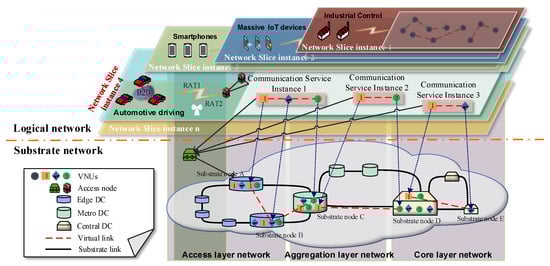
Figure 1.
Example of the VNFs resource allocation for backhaul transport network slices.
3.2. NS Resource of Substrate and Logical Network
Considering the structural characteristics of physical nodes and links, the backhaul transport network is composed of access layer network, aggregation layer network and core layer network. We model the substrate network as a weighted undirected graph , where denotes the set of substrate nodes that provide resources such as computation and storage, and denotes the set of substrate links providing bandwidth resources. Similarly, is the substrate node capacity, is the substrate link bandwidth and is the substrate link length. For example, we use to denote the substrate link between substrate nodes and . The upper bound of available network capacity of substrate node i is denoted by and the maximum bandwidth of the link is denoted by when the traffic is transformed from node i to node j. We use to denote the substrate path mapped by the communication service instance, where the source node is and the terminated node is . We use to denote the length of substrate link when is a segment link of the path that transmits the traffic to the next substrate node for processing or forwarding. Since the path consists of multiple segment links, the path propagation distance is denoted by .
As for the slice, one communication service instance is also modeled by a weighted directed graph , where denotes a set of virtual nodes (instantiated as VNUs carrying certain VNFs), denotes a set of virtual links between virtual nodes and f denotes slice traffic which needs to be forwarded. The communication service chain can be interpreted as an SC, consisting of requested VNUs and virtual links. Let S denote the set of slices and denote an NSI. denotes the slice traffic set of slice s, similarly, denotes the traffic which is needed to be forwarded when the virtual link on the slice s is waiting to map into the substrate network link. We define a binary vector to reflect the adjacency of slice s in the directed graph , i.e., . indicates that two VNUs and are adjacent and connect with a virtual link between the source and destination in the NS s, and otherwise.
3.3. Substrate Node Importance Metric
It is essential to assess the availability of physical nodes so as to select them as hosts for deploying virtual nodes. We model the substrate mode importance metric with topological characteristics of substrate nodes (including degree and betweenness centrality) and network features (including node capacity and current forwarded rate). First, the substrate node resource is typically measured with network features [44] as follows:
where denotes the current capacity of node i and denotes the current bandwidth of link which connects the node i. With combining the topological characteristics of substrate nodes to measure node importance, we weight the parameters in terms of degree and betweenness centrality based on nodes’ normalized metrics [41] and define the node important metric as:
where denotes normalization of the degree of node i, which measures the number of edges that connect to the node. denotes normalization of the betweenness centrality of node i, which quantifies the possibility a node is found between the path linking other pair of nodes.
3.4. Pair-Decision Resource Mapping Relations
In the resource allocation scheme, each substrate node can accommodate multiple VNUs. We assume that each VNU carrying certain VNFs in a slice can only be mapped into one substrate node, which cannot be instantiated to different servers [39]. The VNU is not shared by communication service instances both in the same or different slices for the slice-isolation purpose.
When mapping a communication service instance into substrate network nodes and links, we introduce a binary variable to indicate the mapping relationship between the virtual and substrate nodes. In slice s, we use to stand for that VNU k is mapped into the substrate node , and otherwise. The substrate link between the substrate nodes u and is a segment link of the path , whose resources are allocated to support adjacent VNUs for processing and forwarding, called processing link. For example, Figure 2 illustrates the process for mapping VNUs and virtual links into substrate nodes and links. The communication service chain I possesses two VNUs k and l and a virtual link . The path is the selected substrate path mapped by the communication service chain I and the substrate link , and so on are segment links of the path to transmit the traffic from the source node r to the terminated node v. In particular, u and v are processing substrate nodes that support corresponding VNUs k and l respectively, as well as is the processing link for supporting virtual link .
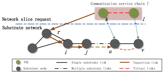
Figure 2.
Illustration of virtual link mapping.
In order to describe the aforementioned mapping relationship, we also introduce a binary variable . Let stand for the virtual link in slice s mapped into substrate link if and only if VNUs k and l are mapped to the substrate nodes u and v respectively at the same time, and otherwise. According to the assumption that one VNU can be only mapped onto one substrate node, and are independent variables. Since both of them are binary variables, can be interpreted as a pair-decision variable by (3).
To avoid the quadratic constraint, such relationship in (3) can be represented by a triangle inequality [45] as:
We can obtain the value of by summing up all the possible values [39] of in , as well as . Since both of them are independent variables, the relationship in (4) can be expressed as:
3.5. Latency Performance
We defined the potential slice traffic as , which is needed to be forwarded when virtual link on the network slice s is mapped into the substrate processing link . Each processing link has an upper-bound capacity that corresponds to the maximum rate over that link for each time instance, defined as . We use to denote the transport network latency, which can be interpreted as a cost function. In order to improve the network load balance, we consider the network characteristics to formulate the transport network latency. The latency formulation consists of two parts. The first part is the transmission time, related to the network capacity limitation of substrate DCs. We use the network capacity and forwarded traffic to capture the number of time-slots required by a substrate link to forward traffic, satisfying the slice target rate. The second part is the propagation time, related to the actual location of mapped substrate DCs and assigned link bandwidth . The transport network latency is defined as follows:
where is a weighting factor, balancing the network characteristics. In this regard, the lower network capacity or the farther location of the mapped substrate node, the higher transport network latency of NSIs.
4. Problem Statement and Algorithm Framework
4.1. Problem Formulation
We propose the resource allocation problem to minimize the backhaul transport latency by mapping all service chains of predefined slices into the appropriate substrate network resources. The problem can be formulated as an ILP with linear constraints, subject to the specific service requirements and network capacity and bandwidth. The inputs to the resource allocation phase are slice traffic, slice latency thresholds, network capacity, and substrate link bandwidth and length. The output is the optimal deployment path for concurrent slice requests that minimizes the transport network latency while meeting the structural characteristics. In this regard, the optimization of latency has two considerations. Network capacity is firstly considered for describing the maximum transmission rate that can be provided for forwarding traffic, which also plays a critical role for network load-balancing. In addition, we also take into account the propagation distance of forwarded traffic in terms of the location of substrate nodes and substrate link bandwidth.
The maximization of total backhaul throughput is equivalent to the minimization of the total number of transmission time [3]. After summarizing the transmission and propagation latency, we can find a latency-optimal mapping path for each communication service instance. The mathematical formulation of the NS resource allocation problem is as follows.
Here, and denote the number of VNUs and communication service instances in the slice s, respectively. Constraint (8) ensures that the hop count for mapping substrate network resources is equal to the number of virtual links in a slice, avoiding the closed-loop path or unnecessary extension of the physical mapping path during link mapping. In order to guarantee the user experience, constraint (9) assures the transport network latency of each NSI will not exceed the latency threshold specified by the service requirement. The threshold might be variable depending on the forwarded traffic or other performance requirements. For example, for an industrial control NSI, the latency threshold will be lower as the service is latency-sensitive, whereas a higher one is set for serving latency-tolerant applications. The amount of required VNUs can not exceed the available substrate resources, so we indicate the corresponding VNU capacity that the substrate processing link accommodates in (10). Constraint (11) ensures that the resource capacity of substrate link can afford the forwarded traffic of slice s to deploy and constraint (12) ensures flow conservation. The amount of flow goes into the substrate node v equals the amount of flow going out of it. Constraint (13) assesses whether the substrate node u and v mapped by the virtual node k and l accordingly are available based on the node importance metric, where and represent the importance of selected substrate nodes u and v respectively and represents the importance threshold.
4.2. Algorithm Framework
The problem described in the previous subsection is an ILP and can be solved by the branch-and-bound scheme [46], where the lower and upper bounds of regions/branches are obtained by solving the relaxation problem. According to the cutting plane approach [3], the relaxation can be iteratively tightened by adding valid inequalities to the formulation. Following, we briefly describe the algorithmic steps.
Relaxation: Relax the original problem and represent the relaxation problem in the standard form. In this stage, we transform the binary variable in the original ILP into a continuous variable and formulate the corresponding problem with ignoring the integer constraint (14). That is, the relaxation problem of the original ILP (RILP), as follows:
Upper bound: Using the simplex algorithm to find a solution to the objective function of RILP and store the value . Z will denote the best solution found so far, and will be used as an upper bound of the original ILP on the feasible region D. We denote the upper bound as and the optimal value of the objective function of the original ILP as , where . If is an integer, is the optimal solution for the original problem.
Branching: If the solution is not an integer, we remove the region (where is the integer part of ) that does not contain any integer solution on the feasible region D. Thus, D is divided into two disjoint parts and . According to the invariant objective function of RILP, we use and as feasible regions respectively. That is, adding two constraints and respectively in the original problem, so as to construct two sub-problems and . If the optimal solution of these two problems is still not an integer, then we continue to choose a non-integer solution and decompose the corresponding sub-problem into two sub-problems. For each sub-problem, if the solution is not a integer, as well as the optimal value of the objective function , we “prune” the corresponding feasible region.
Lower bound: If the solution of sub-problem is an integer and the optimal value of the objective function is , we can obtain a lower bound of the original ILP , denoted as .
Optimal solution: Repeat the aforementioned branching and delimiting process to update the upper and lower bounds of original ILP. Tighten iteratively and “prune” the “branch” until all sub-problems cannot be branched, then we find the optimal solution .
5. Numerical Results and Performance Analysis
In this section, we first describe evaluation scenarios followed by a discussion of numerical results to validate the theoretical analysis of the previous sections. We use the average transport network latency, transport network traffic distribution, average substrate link load [25] and serviceability to evaluate the performance of our proposed NS resource allocation scheme.
Except for minimizing the transport network latency in (P1), other performance metrics include the transport network traffic distribution as defined in (15), the average substrate link load of 5G networks as defined in (16), and the average serviceability as defined in (17) for a given set of NSIs. In our scheme, we consider a three-layer network structure for the backhaul transport network, consisting of the access layer network, aggregation layer network and core layer network. Transport network traffic distribution is the slice traffic ratio distributed over three-layer networks (i.e., the access, aggregation and core layer networks) respectively, which can explain the resource allocation principle of our proposed model. Substrate link load is defined as the slice traffic and mapped physical link capacity ratio. By the comparison with other existing policies, we can observe intuitively whether our approach has a considerable impact on the load balance of three-layer networks. Furthermore, serviceability is the ratio of the number of NSIs which have been successfully mapped and the total number, evaluating the ability of a network to serve the concurrent NS requests [47]. As only a few deployment algorithms of E2E slices can be found in current studies, our algorithms are compared with NSDP and RFPA schemes. NSDP is an ILP problem for slice resource allocation, aiming at minimizing the total bandwidth consumption. The RFPA is compared with our proposed algorithm to evaluate whether our approach has a considerable impact on the load balance, or simply deploying VNFs into the preferred substrate node is enough.
In (15), the total traffic flow of an NS s is denoted by . In (15) and (16), stands for the substrate links in different layer networks, including access layer network, aggregation layer network and core layer network. The total number of substrate network links in different layer networks is denoted by . In (17), the total number of NSIs which requires resource allocation is denoted by , and the number of NSIs that can be served is denoted by .
5.1. Simulation Setup
In evaluation scenarios, the simulation setup includes two main parts: a substrate physical network (i.e., actual communications networks) and logical networks (i.e., communication service instances of NSIs). The sample substrate network topology consists of access layer network, aggregation layer network and core layer network. The number of substrate network nodes is fixed and the substrate link is randomly drawn with specific substrate node connectivity. Each link in the substrate network graph is weighted by link length and bandwidth. As shown in Table 2, the substrate network capacities of the access, aggregation, and core layer networks are set to 40 Gbps, 80 Gbps, and 80 Gbps, respectively, according to the future planning of 5G high-capacity and highly scalable transport network [48,49]. Similarly, the setup of substrate links’ length follows the practical structure of the backhaul network, as given in [50]. The node connectivity can describe the number of physical links, for example, when it is set to 0.4, the current node will randomly connect to 40% of the remaining nodes. Common to all proposals, the average substrate node connectivity is always set to 0.4 or 0.5 for ring protection [39]. In order to test the proposed method in improving the network serviceability, we reduce the connectivity of some nodes, randomly taking values between 0.3 and 0.4. The nodes between different layer networks are randomly connected with the same connectivity. We assume that the substrate link is laid by the optical fiber so that the weight factor of the path transmission is fixed as well. An example of the communications network topology in a timestamp of the simulation is shown in Figure 3, which is a scaled-down version of the practical backhaul transport network. At each timestamp, we generate the substrate network topology randomly according to the node number and node connectivity, as well as the upper bound of network capacity and link length. The comparison value is the average of the results in multiple simulation timestamps to reduce the error. The physical nodes in infrastructure networks are divided into three sets corresponding to the three-layer networks. The access layer network deploys the largest number of nodes with small node spacing and link bandwidth capacity, which is opposite to the characteristics of nodes in the core layer network.
Table 2.
Simulation parameters.
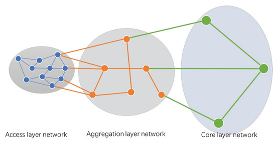
Figure 3.
Example of the backhaul transport network in a simulation timestamp.
For the parameters of NS, we consider the resource allocation over NSIs tailored for three types of services, i.e., the small-volume critical communications (s-VCC) slice, extreme real-time communications (eRTC) slice and enhanced mobile broadband access (eMBB) slice in dense areas. For each slice type, we also initialize three NSIs respectively, where NS 1, 2 and 3 represent the NSIs of s-VCC, NS A, B and C represent the ones of eRTC and NS a, b and c represents the ones of eMBB.
As slice performance requirements explicitly differentiate, the corresponding slice traffic volume and latency threshold are reasonably set according to the slice type [29,41], as shown in Table 2. The topology of traffic flow in an NSI is randomly generated with 8 VNFs weighted by the forwarded traffic demands. According to the assumption, each VNF is only used once at most in the topology of a communication service instance. Table 2 summarizes the simulation parameters.
5.2. Numerical Results
5.2.1. Transport Network Latency
We first analyze the transport network latency when allocating resources over s-VCC slices, eRTC slices and eMBB slices concurrently. There are two simulation environments, uniform and non-uniform VNU capacity in substrate nodes, as shown in Table 2. The VNU capacity indicates the number of VNUs that a substrate network node can accommodate. Under the uniform VNU capacity condition, Figure 4a compares the transport network latency among three type slices and the latency threshold which depends on the class of services. We can notice our model provides an excellent latency for all NSIs without exceeding the required latency threshold.
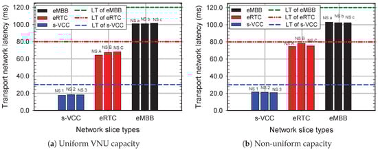
Figure 4.
Transport network latency for different network slices when the VNU capacity of DCs is uniform and non-uniform.
The assumption of uniform VNU capacity can be ideal sometimes, since the VNU availability in substrate networks is time-varying. The reasons can be, for instance, the time-varying switch port/interface failures [51]. Consequently, in Figure 4b, we evaluate the same transport network latency under the non-uniform VNU capacity, which gradually decreases in the core, aggregation and access layer networks. As expected, the ultra-low latency requirement of latency-sensitive slices, including s-VCC slices and eRTC slices, is satisfied as well, while the latency increases slightly comparing to Figure 4a. It also proved that minimizing the backhaul transport latency is necessary for preventing the extreme service requirements from deteriorating due to time-varying network and unexpected traffic.
The network capacity in three-layer networks is different: the link capacity can be lower in the access layer network, and higher as moving into the core layer network. In this regard, we change the connectivity of substrate nodes in access layer network from 5% to 60% to analyze the transport network latency over three types of service-oriented slices. Changing network node connectivity will increase/decrease network capacity in the access layer network, aiming to simulate time-varying and deteriorating network scenarios. In Figure 5, we can observe that the latency of both types of latency-sensitive slices reduce significantly with node connectivity due to increasing access layer network resources. This outcome shows that the provisioning of ultra-low latency demands largely relies on the allocating edge DCs’ resources. Or other, unnecessary latency is mainly generated by redundant path allocation if the target rate can be provided, conforming to our design principles.
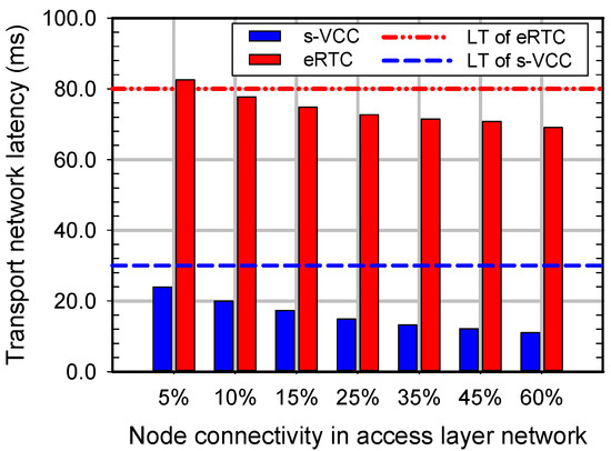
Figure 5.
Transport network latency for latency-sensitive network slices vs node connectivity in access layer network.
To obviously evaluate the latency, we use the proposed scheme, NSDP scheme and RFPA scheme to deploy three type slices concurrently. Figure 6 compares the transport network latency with the increased number of slices. We observe a latency reduction in our model of up to 30.01% and 41.63% compared to the NSDP and RFPA respectively. As a result, our model provides a minimal transport network latency, which is far lower than others and increases slowly with the amount of concurrent NSIs. Such result is that our model tries to balance the link load in access, aggregation and core layer networks, so that edge DCs’ resources are reserved to latency-sensitive NSIs as much as possible for transmission distance reduction. In addition, other approaches disregard the low transmission rate generated by poor link capacity provided to the massive traffic of eMBB.
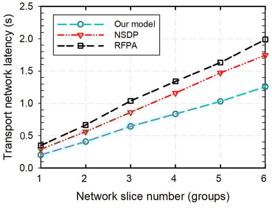
Figure 6.
Transport network latency comparison among proposed model, NSDP and RFPA.
5.2.2. Transport Network Traffic Distribution
We analyze the average traffic distribution for s-VCC slice, eRTC slice and eMBB slice respectively under the uniform and non-uniform VNU capacity conditions, presented in Figure 7. In Figure 7a, all s-VCC slice traffic deploys into access layer network resources, whereas most of the eRTC slice traffic and all eMBB slice traffic deploys into aggregation and core layer network resources. For the case with non-uniform VNU capacity, Figure 7b reveals the similar result as Figure 7a, whereas the traffic distributions of three type slices move backward, obviously. It can be proved that the s-VCC slice has a higher priority to occupy access layer network resources for ultra-lower latency in our proposed model. The detailed reason is that the shorter transmission distance can effectively reduce the latency, and has been proven in the above simulation results. Meanwhile, the eMBB slice traffic prefers to be deployed into the core layer network which owns powerful capacity and bandwidth to support the high traffic volume of such slices. Furthermore, Figure 7a depicts that the traffic of latency-tolerant NSIs, e.g., eMBB, goes into the aggregation or core layer network for computation offloading of the access layer network when the VNU capacity is limited.
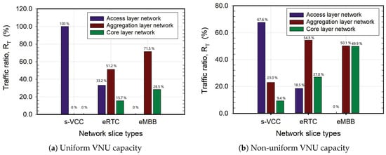
Figure 7.
Transport network traffic distribution when the VNU capacity of DCs is uniform and non-uniform.
In order to further evaluate the traffic distribution principle for three type slices, we evaluate the average traffic distribution when the node connectivity changes in the access layer network, as shown in Figure 8. In Figure 8a,b, the traffic ratios of the s-VCC slice and eRTC slice on access layer network increase continuously with increased node connectivity, whereas the ones on aggregation layer network increase first and then decrease. In contrast, the traffic ratio on core layer network continues to decrease to 0, because of the insufficient access layer network resources when the node connectivity is lower. Comparing to the eRTC slice, we can notice that the traffic ratio of the s-VCC slice on aggregation layer network drops preferentially and reaches 0 eventually. The phenomenon can be attributed to the allocation principle: a higher allocation priority is provided to the s-VCC slice for latency reduction, since its latency demand is further stricter. On the contrary, the traffic of eMBB goes into the core layer network observably as shown in Figure 8c. Because of eMBB’s massive traffic, the link capacity of access layer network cannot afford the target rate. When the node connectivity is greater than 35%, the traffic ratio on core layer network drops down visibly. The reason is that the access layer network resource is sufficient enough to accommodate more slice traffic, so more aggregation layer network resources are released for eMBB NSIs.
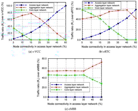
Figure 8.
Transport network traffic distribution over s-VCC, eRTC and eMBB vs node connectivity in access layer network.
5.2.3. Substrate Link Load
For evaluating the resource utilization outcomes, we compare the average substrate link load among the proposed scheme, NSDP and RFPA schemes in three-layer networks over increased node connectivity. As expected, our model presents a better performance compared to others, trying to balance resource utilization in the whole transport network. In Figure 9a, three models show similar behavior on nearly 100% allocating the access layer network resources at the beginning. However, as the connectivity of nodes increases, the resource utilization of our model drops significantly in the access layer network to avoid network overload. It can be proved that our model considers the network load, instead of over-occupied the access layer network resources for reducing transmission distance. In the aggregation and core layer networks, Figure 9b,c present that the network load in aggregation layer network is high in RFPA scheme, whereas the powerful computation resources in core layer network are disregarded. In our model and NDSP scheme, the trend of resource utilization is similar in the two-layer networks at the beginning. Nevertheless, one interesting observation is that the gap between our model and NSDP widens when we increase the node connectivity, especially in the core layer network. It reveals that our model considers network capacity and link bandwidth jointly, tries to evenly deploy three-layer network resources to balance the network load with a better allocation principle. Compared with over-deploying access layer network resources in NSDP and RFPA schemes, our model tries to reserve more edge DC resources and evenly deploy three-layer network resources.
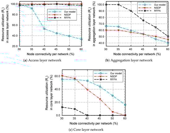
Figure 9.
Average substrate link load in three-layer networks comparing among proposed model, NSDP and RFPA.
5.2.4. Serviceability
The average serviceability of a network indicates the ratio of NSIs that substrate networks can serve simultaneously for a given set of concurrent slice requests. In Figure 10, we analyze the relationship between the latency threshold of eRTC slice and the serviceability of three models under the same simulation scenario. As expected, our model has the highest growth trend and can reach more acceptance with extreme service requirements, for example, approximately 85% acceptance when the latency threshold of eRTC slice is set to the common value, 80 ms. It reveals that our model can simultaneously serve a larger scale of concurrent NS requests or support lower latency. When relaxing the latency threshold of the eRTC slice to 110 ms, the serviceabilities of our model and NSDP scheme reach 100% acceptance. However, the QoS of eRTC will decline with poor transport network latency, as its latency threshold is set to 110 ms, which is much higher than the extreme latency requirements. Therefore, the advantages of our model are no longer obvious after increasing the certain latency threshold. The reason is that our model pays more attention to reduce the transport network latency, rather than attaining the optimal use of network resources.
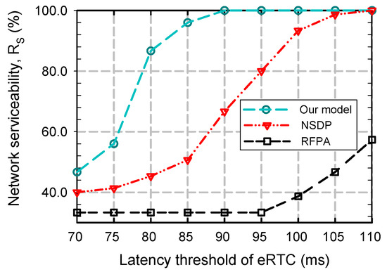
Figure 10.
Serviceability comparison among the proposed model, NSDP and RFPA.
6. Conclusions
NS offers a number of significant advantages in supporting diverse and extreme requirements for latency, throughput, capacity and availability in 5G future communications networks. By slicing a physical network into logically independent virtual networks, the characteristics of applications can be better taken into account by implementing their own resource allocation policies in each slice. In order to satisfy extreme service demands, such as ultra-low latency, high bandwidth and good user experience, how to coordinate the infrastructure network characteristics and QoS with an appropriate policy is the most important research issue when deploying the E2E slices into the backhaul transport network.
In this paper, we first consider the substrate network characteristics and topology-aware slices (i.e., including VNUs and virtual links) and model the pair-decision resource allocation to construct mapping relationships on account of mapping virtual nodes and links in a coordinated way. To further minimizing the latency, we formulate a latency-optimal VNF resource allocation problem to improve the extreme QoS (such as URLLC) and user experience (such as eMBB). By enclosing the formulation with ILP and solving the problem with the branch-and-bound scheme, an optimal deployment path is found out. Here, latency is characterized by jointly taking into account the network capacity, DCs’ locations and link bandwidth. Furthermore, a node importance metric is employed to analyze the DCs’ availability and priority in the substrate network. Simulation results show that the proposed scheme can provide lower transport network latency, with a reduction of up to 30% and 41.63% compared to the NSDP and RFPA respectively. The analysis of average traffic distribution, substrate link load and serviceability prove that our proposed scheme achieves a better network load balance and serves a larger scale of concurrent slice requests.
Author Contributions
Conceptualization, W.L., Y.Z. and L.F.; methodology, W.L., Y.Z. and L.F.; software, Y.Z.; validation, Y.Z. and L.F.; formal analysis, Y.Z. and L.F.; writing—original draft preparation, Y.Z.; writing—review and editing, Y.Z., L.F. and F.Z.; visualization, Y.Z.; supervision, W.L. and X.Q.; project administration, W.L.; funding acquisition, W.L., L.F., P.Y and X.Q.
Funding
This work has been supported by National Science and Technology Major Project (Grant No. 2018ZX030110004) and State Grid Science and Technology project “Analysis of Power Wireless Private Network Evolution and 4G/5G Technology Application.
Conflicts of Interest
The authors declare no conflict of interest.
References
- Alliance, N. 5G white paper. In Next Generation Mobile Networks, White Paper; NGMN: Frankfurt, Germany, 17 February 2015; pp. 1–125. [Google Scholar]
- Timalsina, S.K.; Bhusal, R.; Moh, S. NFC and its application to mobile payment: Overview and comparison. In Proceedings of the 2012 8th International Conference on Information Science and Digital Content Technology (ICIDT2012), Jeju, Korea, 26–28 July 2012; Volume 1, pp. 203–206. [Google Scholar]
- Pateromichelakis, E.; Samdanis, K.; Wei, Q.; Spapis, P. Slice-Tailored Joint Path Selection and Scheduling in mm-Wave Small Cell Dense Networks. In Proceedings of the GLOBECOM 2017—2017 IEEE Global Communications Conference, Singapore, 4–8 December 2017; pp. 1–6. [Google Scholar] [CrossRef]
- Zhang, H.; Liu, N.; Chu, X.; Long, K.; Aghvami, A.; Leung, V.C.M. Network Slicing Based 5G and Future Mobile Networks: Mobility, Resource Management, and Challenges. IEEE Commun. Mag. 2017, 55, 138–145. [Google Scholar] [CrossRef]
- Fischer, A.; Botero, J.F.; Beck, M.T.; de Meer, H.; Hesselbach, X. Virtual Network Embedding: A Survey. IEEE Commun. Surv. Tutor. 2013, 15, 1888–1906. [Google Scholar] [CrossRef]
- Esposito, F.; Matta, I.; Ishakian, V. Slice embedding solutions for distributed service architectures. ACM Comput. Surv. 2013, 46, 6. [Google Scholar] [CrossRef]
- Bari, F.; Chowdhury, S.R.; Ahmed, R.; Boutaba, R.; Duarte, O.C.M.B. Orchestrating Virtualized Network Functions. IEEE Trans. Netw. Serv. Manag. 2016, 13, 725–739. [Google Scholar] [CrossRef]
- Riggio, R.; Bradai, A.; Harutyunyan, D.; Rasheed, T.; Ahmed, T. Scheduling Wireless Virtual Networks Functions. IEEE Trans. Netw. Serv. Manag. 2016, 13, 240–252. [Google Scholar] [CrossRef]
- Ibrahim, A.; Tarik, T.; Konstantinos, S.; Adlen, K.; Hannu, F. Network Slicing and Softwarization: A Survey on Principles, Enabling Technologies, and Solutions. IEEE Commun. Surv. Tutor. 2018, 20, 2429–2453. [Google Scholar] [CrossRef]
- Qu, L.; Assi, C.; Shaban, K.; Khabbaz, M.J. A Reliability-Aware Network Service Chain Provisioning with Delay Guarantees in NFV-Enabled Enterprise Datacenter Networks. IEEE Trans. Netw. Serv. Manag. 2017, 14, 554–568. [Google Scholar] [CrossRef]
- Kumar, R.; Hasan, M.; Padhy, S.; Evchenko, K.; Piramanayagam, L.; Mohan, S.; Bobba, R.B. End-to-End Network Delay Guarantees for Real-Time Systems Using SDN. In Proceedings of the 2017 IEEE Real-Time Systems Symposium (RTSS), Paris, France, 5–8 December 2017; pp. 231–242. [Google Scholar] [CrossRef]
- Wu, J.; Tse, C.K.; Lau, F.C.M. Optimizing Performance of Communication Networks: An Application of Network Science. IEEE Trans. Circuits Syst. II Express Briefs 2015, 62, 95–99. [Google Scholar] [CrossRef]
- Kim, Y.; Hong, B.; Choi, W. Scale-Free Wireless Networks with Limited Degree Information. IEEE Wirel. Commun. Lett. 2012, 1, 428–431. [Google Scholar] [CrossRef]
- Baumgartner, A.; Bauschert, T.; Koster, A.M.C.A.; Reddy, V.S. Optimisation Models for Robust and Survivable Network Slice Design: A Comparative Analysis. In Proceedings of the GLOBECOM 2017—2017 IEEE Global Communications Conference, Singapore, 4–8 December 2017; pp. 1–7. [Google Scholar] [CrossRef]
- Carpio, F.; Dhahri, S.; Jukan, A. VNF placement with replication for load balancing in NFV networks. In Proceedings of the 2017 IEEE International Conference on Communications (ICC), Paris, France, 21–25 May 2017; pp. 1–6. [Google Scholar] [CrossRef]
- Chatras, B.; Kwong, U.S.T.; Bihannic, N. NFV enabling network slicing for 5G. In Proceedings of the 2017 20th Conference on Innovations in Clouds, Internet and Networks (ICIN), Paris, France, 7–9 March 2017; pp. 219–225. [Google Scholar] [CrossRef]
- Wen, R.; Feng, G.; Tan, W.; Ni, R.; Qin, S.; Wang, G. Protocol Function Block Mapping of Software Defined Protocol for 5G Mobile Networks. IEEE Trans. Mob. Comput. 2018, 17, 1651–1665. [Google Scholar] [CrossRef]
- An, X.; Zhou, C.; Trivisonno, R.; Guerzoni, R.; Kaloxylos, A.; Soldani, D.; Hecker, A. On end to end network slicing for 5G communication systems. Trans. Emerg. Telecommun. Technol. 2017, 28, e3058. [Google Scholar] [CrossRef]
- Richart, M.; Baliosian, J.; Serrat, J.; Gorricho, J. Resource Slicing in Virtual Wireless Networks: A Survey. IEEE Trans. Netw. Serv. Manag. 2016, 13, 462–476. [Google Scholar] [CrossRef]
- Mijumbi, R.; Serrat, J.; Gorricho, J.; Bouten, N.; Turck, F.D.; Boutaba, R. Network Function Virtualization: State-of-the-Art and Research Challenges. IEEE Commun. Surv. Tutor. 2016, 18, 236–262. [Google Scholar] [CrossRef]
- Sherwood, R.; Gibb, G.; Yap, K.K.; Appenzeller, G.; Casado, M.; McKeown, N.; Parulkar, G.M. Can the production network be the testbed? In Proceedings of the 9th USENIX Conference on Operating Systems Design and Implementation, Vancouver, BC, Canada, 4–6 October 2010; Volume 10, pp. 1–6. [Google Scholar]
- Jin, X.; Li, L.E.; Vanbever, L.; Rexford, J. Softcell: Scalable and flexible cellular core network architecture. In Proceedings of the Ninth ACM Conference on Emerging Networking Experiments and Technologies, Santa Barbara, CA, USA, 9–12 December 2013; pp. 163–174. [Google Scholar]
- Sama, M.R.; An, X.; Wei, Q.; Beker, S. Reshaping the mobile core network via function decomposition and network slicing for the 5G Era. In Proceedings of the 2016 IEEE Wireless Communications and Networking Conference, Doha, Qatar, 3–6 April 2016; pp. 1–7. [Google Scholar] [CrossRef]
- Ashwin, G.; Sidharth, S.; Tamal, D.; Aniruddha, K. Strategies for VNF placements in large provider networks. In Proceedings of the 2017 Optical Fiber Communications Conference and Exhibition (OFC), Los Angeles, CA, USA, 19–23 March 2017; pp. 1–3. [Google Scholar]
- Carpio, F.; Bziuk, W.; Jukan, A. Replication of Virtual Network Functions: Optimizing link utilization and resource costs. In Proceedings of the 2017 40th International Convention on Information and Communication Technology, Electronics and Microelectronics (MIPRO), Opatija, Croatia, 22–26 May 2017; pp. 521–526. [Google Scholar] [CrossRef]
- Mijumbi, R.; Hasija, S.; Davy, S.; Davy, A.; Jennings, B.; Boutaba, R. Topology-Aware Prediction of Virtual Network Function Resource Requirements. IEEE Trans. Netw. Serv. Manag. 2017, 14, 106–120. [Google Scholar] [CrossRef]
- Khebbache, S.; Hadji, M.; Zeghlache, D. Scalable and cost-efficient algorithms for VNF chaining and placement problem. In Proceedings of the 2017 20th Conference on Innovations in Clouds, Internet and Networks (ICIN), Paris, France, 7–9 March 2017; pp. 92–99. [Google Scholar] [CrossRef]
- Ghaznavi, M.; Khan, A.; Shahriar, N.; Alsubhi, K.; Ahmed, R.; Boutaba, R. Elastic virtual network function placement. In Proceedings of the 2015 IEEE 4th International Conference on Cloud Networking (CloudNet), Niagara Falls, ON, Canada, 5–7 October 2015; pp. 255–260. [Google Scholar] [CrossRef]
- Alleg, A.; Ahmed, T.; Mosbah, M.; Riggio, R.; Boutaba, R. Delay-aware VNF placement and chaining based on a flexible resource allocation approach. In Proceedings of the 2017 13th International Conference on Network and Service Management (CNSM), Tokyo, Japan, 26–30 November 2017; pp. 1–7. [Google Scholar] [CrossRef]
- Bari, M.F.; Chowdhury, S.R.; Ahmed, R.; Boutaba, R. On orchestrating virtual network functions. In Proceedings of the 2015 11th International Conference on Network and Service Management (CNSM), Barcelona, Spain, 9–13 November 2015; pp. 50–56. [Google Scholar]
- Nguyen, L.D.; Duong, T.Q.; Nguyen, D.N.; Tran, L. Energy efficiency maximization for heterogeneous networks: A joint linear precoder design and small-cell switching-off approach. In Proceedings of the 2016 IEEE Global Conference on Signal and Information Processing (GlobalSIP), Washington, DC, USA, 7–9 December 2016; pp. 718–722. [Google Scholar] [CrossRef]
- Nguyen, L.D.; Tuan, H.D.; Duong, T.Q.; Dobre, O.A.; Poor, H.V. Downlink Beamforming for Energy-Efficient Heterogeneous Networks With Massive MIMO and Small Cells. IEEE Trans. Wirel. Commun. 2018, 17, 3386–3400. [Google Scholar] [CrossRef]
- Nguyen, L.D.; Tuan, H.D.; Duong, T.Q. Energy-Efficient Signalling in QoS Constrained Heterogeneous Networks. IEEE Access 2016, 4, 7958–7966. [Google Scholar] [CrossRef]
- Nguyen, L. Resource allocation for energy efficiency in 5G wireless networks. EAI Endorsed Trans. Ind. Netw. Intell. Syst. 2018, 5, 6. [Google Scholar] [CrossRef]
- Long, D.N.; Tuan, H.D.; Duong, T.Q.; Poor, H.V. Multi-cell Massive MIMO Beamforming in Assuring QoS for Large Numbers of Users. arXiv, 2017arXiv:1712.03548.
- Long, D.N.; Tuan, H.D.; Duong, T.Q.; Poor, H.V. Beamforming and power allocation for energy-efficient massive MIMO. In Proceedings of the International Conference on Digital Signal Processing, London, UK, 23–25 August 2017. [Google Scholar]
- Nguyen, L.D.; Duong, T.Q.; Ngo, H.Q.; Tourki, K. Energy Efficiency in Cell-Free Massive MIMO with Zero-Forcing Precoding Design. IEEE Commun. Lett. 2017, 21, 1871–1874. [Google Scholar] [CrossRef]
- Kwak, J.; Moon, J.; Lee, H.; Le, L.B. Dynamic network slicing and resource allocation for heterogeneous wireless services. In Proceedings of the 2017 IEEE 28th Annual International Symposium on Personal, Indoor, and Mobile Radio Communications (PIMRC), Montreal, QC, Canada, 8–13 October 2017; pp. 1–5. [Google Scholar] [CrossRef]
- Wen, R.; Tang, J.; Quek, T.Q.S.; Feng, G.; Wang, G.; Tan, W. Robust Network Slicing in Software-Defined 5G Networks. In Proceedings of the GLOBECOM 2017—2017 IEEE Global Communications Conference, Singapore, 4–8 December 2017; pp. 1–6. [Google Scholar] [CrossRef]
- Taleb, T.; Mada, B.; Corici, M.; Nakao, A.; Flinck, H. PERMIT: Network Slicing for Personalized 5G Mobile Telecommunications. IEEE Commun. Mag. 2017, 55, 88–93. [Google Scholar] [CrossRef]
- Guan, W.; Wen, X.; Wang, L.; Lu, Z.; Shen, Y. A Service-Oriented Deployment Policy of End-to-End Network Slicing Based on Complex Network Theory. IEEE Access 2018, 6, 19691–19701. [Google Scholar] [CrossRef]
- China Mobile Communications Corporation; Huawei Technologies Co., Ltd.; Deutsche Telekom AG; Volkswagen. 5G Service-Guaranteed Network Slicing White Paper. In Proceedings of the 2017 Mobile World Conference (MWC 2017), Barcelona, Spain, 27 February–2 March 2017; Volume 1, pp. 1–26. [Google Scholar]
- Nguyen, V.; Brunstrom, A.; Grinnemo, K.; Taheri, J. SDN/NFV-Based Mobile Packet Core Network Architectures: A Survey. IEEE Commun. Surv. Tutor. 2017, 19, 1567–1602. [Google Scholar] [CrossRef]
- Chowdhury, M.; Rahman, M.R.; Boutaba, R. ViNEYard: Virtual Network Embedding Algorithms With Coordinated Node and Link Mapping. IEEE/ACM Trans. Netw. 2012, 20, 206–219. [Google Scholar] [CrossRef]
- Tversky, A.; Gati, I. Similarity, separability, and the triangle inequality. Psychol. Rev. 1982, 89, 123. [Google Scholar] [CrossRef]
- Naddef, D.; Rinaldi, G. Branch-and-cut algorithms for the capacitated VRP. In The Vehicle Routing Problem; Society for Industrial and Applied Mathematics: Philadelphia, PA, USA, 2002; pp. 53–84. [Google Scholar]
- Dao, N.; Lee, J.; Vu, D.; Paek, J.; Kim, J.; Cho, S.; Chung, K.; Keum, C. Adaptive Resource Balancing for Serviceability Maximization in Fog Radio Access Networks. IEEE Access 2017, 5, 14548–14559. [Google Scholar] [CrossRef]
- Moreolo, M.S.; Nadal, L.; Fabrega, J.M. Towards advanced high capacity and highly scalable software defined optical transmission. In Proceedings of the 2017 19th International Conference on Transparent Optical Networks (ICTON), Girona, Spain, 2–6 July 2017; pp. 1–4. [Google Scholar] [CrossRef]
- Preyss, N.; Burg, A. Experimental signal-quality characterization of a high-capacity mmWave link for backhaul applications. In Proceedings of the 2016 IEEE Sensor Array and Multichannel Signal Processing Workshop (SAM), Rio de Janerio, Brazil, 10–13 July 2016; pp. 1–5. [Google Scholar] [CrossRef]
- Wong, E.; Grigoreva, E.; Wosinska, L.; Machuca, C.M. Enhancing the survivability and power savings of 5G transport networks based on DWDM rings. IEEE/OSA J. Opt. Commun. Netw. 2017, 9, D74–D85. [Google Scholar] [CrossRef]
- Smith, W.E.; Trivedi, K.S.; Tomek, L.A.; Ackaret, J. Availability analysis of blade server systems. IBM Syst. J. 2008, 47, 621–640. [Google Scholar] [CrossRef]
© 2019 by the authors. Licensee MDPI, Basel, Switzerland. This article is an open access article distributed under the terms and conditions of the Creative Commons Attribution (CC BY) license (http://creativecommons.org/licenses/by/4.0/).