Featured Application
The proposed electromagnetic-ring active balancing actuator can be integrated into the machine tool spindles and effectively decrease the unbalance vibration of spindles in the normal working process.
Abstract
Active balancing actuators are essential components of intelligent machine tool spindles to automatically reduce the unbalance vibration and promote machining accuracy and efficiency. In this study, a novel electromagnetic-ring actuator is introduced, which can be integrated into the hollow rotor of the spindle and compensate the initial mass imbalance through step rotation of two counterweight discs driven by the magnetic field. The working principle of the actuator is described in detail and its performance is analyzed, including balancing ability, balancing accuracy and self-lock capacity. To control the normal operation of the actuator, a phase detection and control program was developed. Finally, to verify the effectiveness of the novel actuator, function experiments and active balancing experiments were carried out. The experimental results show that the novel actuator could reduce the unbalance vibration of the machine tool spindle by 87.5% at 3600 rpm.
1. Introduction
The spindle is the core functional component of a machine tool and its performance directly determines the technical level of the machine tool. With the promotion of Industry 4.0 technology, intelligent spindles integrated with actuators and sensors will be the direction of future development of machine tool spindles [1,2]. These actuators are considered as legs and arms of intelligent spindles, including chatter suppression actuators [3,4,5,6], thermal error compensation actuators [7,8], bearing preload actuators [9,10], active balancing actuators [11] and so forth.
Active balancing actuators are used to automatically reduce the unbalance vibration of machine tool spindles during the working process. Although the spindles are accurately pre-balanced by the manufacturer before delivery, due to asymmetrical installation of tools/workpieces, positioning errors between tool and spindle or even non-uniform wear of tools in cutting, the rotor system will still produce new mass imbalances, which can result in increased vibration of the machine tool and decreased machining accuracy and efficiency. Therefore, it is necessary to frequently do dynamic balancing of spindles in workshops. In general, the dynamic balancing of spindles is a manual and iterative process, requiring experienced technicians and a lot of time [12,13,14]. For intelligent spindles, the balancing process must be automatic, without human intervention, so the requirement of engineering promotes the development of active balancing actuators. In recent years, several types of active balancing actuators have been invented, including magnetic-bearing type [15,16], liquid-type [17,18,19], electromechanical type [20] and electromagnetic-ring type [21,22]. Because electromagnetic-ring actuators have the advantages of compact structure, fast response speed and high accuracy, they have great potential to integrate into the machine tool spindles and have been developed as a commercial product by several manufacturers [23,24]. However, existing electromagnetic-ring actuators can be only installed outside of the rotor, generally at the root of the extension section of the spindle and waste part of the spindle processing space. If the actuator can be installed inside the rotor, it is better for intelligent spindle integration and its scope of engineering application can be extended.
To solve the problem, this work proposes a novel electromagnetic-ring actuator for the hollow rotor of the machine tool spindle. The paper is organized as follows: Section 2 describes the working principle of the actuator, including the balancing system, the magnetic circuit, the step rotation and differences from existing actuators. Section 3 analyzes the basic performance of the actuator, such as the balancing ability, balancing accuracy and self-lock capacity. Section 4 introduces the control strategy of the actuator and develops the phase detection and control program. To verify the effectiveness of the novel actuator, function and active balancing experiments are carried out in Section 5 and conclusions are presented in Section 6.
2. Working Principle of Electromagnetic-Ring Balancing Actuator
2.1. Balancing System
As shown in Figure 1, the electromagnetic-ring active balancing system is mainly composed of four parts: the data collection unit, the control unit, the power supply unit and the actuator. The working principle of the system is as follows: The vibrations of the machine tool spindle are measured by a set of sensors, such as displacement probes or accelerometers. Through the analog input module of the data collection unit, these vibration signals are sampled to a manageable data form and then transmitted to the control unit. The control unit continuously monitors the unbalance vibration amplitude of the spindle and compares it to a set value. When the amplitude is higher than the set value, the control unit forms control commands according to the unbalance vibration parameters and sends them to the power supply unit through the I/O module of the data collection unit. The required electrical signals are supplied by the power supply unit and fed to the balancing actuator installed in the hollow rotor of the machine tool spindle. According to the electrical signals, the mass distribution of the actuator is changed, a compensation mass is produced to balance the rotor system and the unbalance vibration is decreased accordingly. When the amplitude of the unbalance vibration is lower than the set value again, the control unit stops to output the control commands and continuously monitors the vibration of the machine tool spindle.
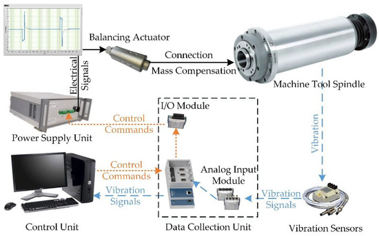
Figure 1.
Working principle of the balancing system.
2.2. Basic Structure of the Balancing Actuator
As the balancing actuator is the terminal actuator of the active balancing system, its performance determines the final effect of the system, so its design is the core content of active balancing technology research.
2.2.1. Structure Design
As shown in Figure 2, the balancing actuator comprises a rotatory part and a stationary part. The rotatory part rotates with the hollow rotor during operation and decreases the unbalance vibration through the inner mass distribution. The stationary part stays still during operation, receives electrical signals from the power supply unit and generates the magnetic field to drive the action of the rotatory part. The stationary part consists of two coils with respective coil cases, one center stator and several bolts to connect them. The central stator is machined with a through hole which is the wire channel to connect the power supply unit with the two coils. The rotatory part consists of an actuator case, two cover plates, four iron tooth rings, two counterweight discs with counterweight, two ball bearings and so forth. The actuator case is used to connect the actuator with the hollow rotor of the spindle and can be designed according to the size of the inner hole. Because the inner hole of the rotor used in the balancing experiment is conical, the case is also conical and the conical degrees are the same. The other components of the rotatory part are symmetrical in pairs and all of them are connected with the actuator case. For example, four iron tooth rings can be divided into two pairs, each pair contains an outside ring and an inside ring and their specific working principle is introduced below. The two inside rings are machined with a through hole to connect the center stator. Because they have relative movement during operation, an air gap is needed to prevent friction and two ball bearings are adopted to guarantee their long-cycle operation.
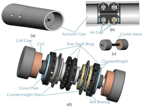
Figure 2.
Three-dimensional model of the balancing actuator: (a) Global shape; (b) Rotatory part; (c) Stationary part; (d) Exploded view.
2.2.2. Magnetic Circuit Analysis
The electromagnetic ring actuator proposed in this study is an axisymmetric structure, so one quarter structure is used to design the magnetic circuit in Figure 3. The coil case, center stator and inside and outside tooth rings are all magnetic conductive materials. When the coil is powered on, the coil case is instantly magnetized and a magnetic field is generated. The direction of the magnetic field is determined by the coil voltage. When the coil voltage is alternately changed between positive and negative, the direction of the magnetic field is alternately changed clockwise and counterclockwise. Through the air gap δ1 and δ2 between the rotatory part and stationary part, the magnetic field is transferred to the rotatory part, the inside and outside tooth rings are correspondingly magnetized and an N-pole and S-pole are produced on top of the teeth of the two tooth rings. Permanent magnets are mounted on the counterweight disc. According to the principle of "same-sex exclusion, opposite-sex attraction" of magnets, the counterweight disc is driven to step rotate based on the magnetic force between the magnetized tooth rings and permanent magnets.
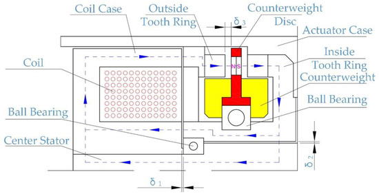
Figure 3.
Magnetic circuit of the balancing actuator.
2.2.3. Principle of Step Rotation
The action of the counterweight disc is the core of the balancing actuator, which requires not only synchronous rotation with the actuator but also step rotation relative to the tooth rings. To realize these two requirements, the magnetic force between the counterweight disc and the tooth rings should be analyzed.
As shown in Figure 4, the outer circumference of the counterweight disc is equipped with permanent magnets with equal spacing and the polarity of the adjacent permanent magnets is opposite. The tooth ring is a tooth-shaped structure with rectangular teeth; width W1 is equal to the space between two adjacent permanent magnets and width W2 is equal to the length of the permanent magnets. The counterweight block is bolted to the counterweight disc. When the counterweight disc rotates step by step, the center line of the counterweight block is correspondingly changed and the mass distribution is also changed.
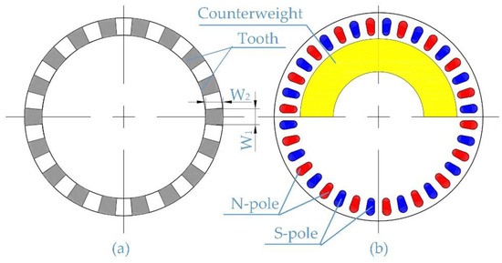
Figure 4.
Axial view of the two components: (a) Tooth ring; (b) Counterweight disc.
The normal condition of the balancing actuator is the self-lock condition, shown in Figure 5a. The self-lock force is generated by the magnetic force between the permanent magnets and the tooth rings. Under the self-lock force, the counterweight disc can synchronously rotate with the balancing actuator with no mass distribution changes. When the coil is powered on, the tooth rings are quickly magnetized. In case of counter clockwise rotation, the two tooth rings are magnetized to the N and S poles, respectively, shown in Figure 5b. The counterweight disc is driven by the total magnetic force to step rotate relative to the magnetized tooth rings. When the counterweight disc moves to the middle position of each step in Figure 5c, the angular velocity of the counterweight disc reaches the maximum, the coil is then powered off and the magnetic field disappears. Under the self-lock force, the counterweight disc slows down gradually and stops at the end of each step shown in Figure 5d. Through one step rotation, the counterweight plate rotates a fixed angle relative to the actuator. If the counterweight disc is needed to move on, a magnetic field in the opposite direction in Figure 5e is required through the opposite voltage of the coil. Assuming the magnetic field in one direction is continuously supplied, the counterweight disc will do reciprocating motion around one position and the motion should be strictly forbidden.
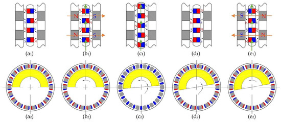
Figure 5.
Step rotary process of the balancing actuator: (a) Self-lock condition; (b) Start-up of step rotation; (c) Middle of step rotation; (d) End of step rotation; (e) Start-up of next step.
2.3. Comparisons with Existing Electromagnetic-Ring Balancing Actuator
The existing electromagnetic-ring (EM-ring) balancing actuator is widely used in the spindles of machine tools, such as grinding, turning and milling tools [23]. As shown in Figure 6, the balancing ring for the shaft assembly includes two balancing rotors (called counterweight discs in this paper) and these two rotors, fixed by magnetic forces, are actuated by the electromagnetic fields of the stator coils, which is the same as the new actuator proposed in this study. However, there are several obvious differences between these two balancing actuators: (1) the balancing ring and stator of the existing balancer are installed independently, which is difficult in field installation to adjust the small gap between these two parts, while the balancing ring and stator of the new balancer are integrated and the gap is pre-adjusted, which greatly reduces the difficulty of installation; (2) the gap between the ring and stator of the new actuator can be smaller than the existing one, so the transfer efficiency of the magnetic field is higher and the required current is lower; (3) the existing actuator can only be installed outside of the rotor, generally at the root of the extension section of the spindle, while the new actuator can be installed into the rotor, broadening its application; and (4) the magnetic circuit of the new actuator is redesigned to suit the new installation method, which is better for transferring magnetic field. Specific parameters of these two actuators are shown in Table 1. According to the comparison results, although the balancing speed of the new actuator is a little lower than the existing actuators, the new actuator has great advantages in the structural dimensions and balancing ability, which verifies the superiority of the new actuator.
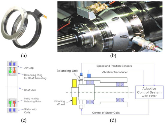
Figure 6.
Working principle of existing electromagnetic-ring balancing actuator: (a) Physical map of the balancing actuator; (b) Spindle with balancing actuator; (c) Sectional view of balancing actuator; (d) Components of balancing system.

Table 1.
Parameter comparison between the existing actuator and the new actuator.
3. Performance Analysis of the Balancing Actuator
3.1. Balancing Ability
According to the working principle of the actuator introduced in Section 2.2, the mass distribution of the actuator is mainly determined by the two counterweight discs with counterweight blocks. As shown in Figure 7, there are two symmetrical counterweight discs in the actuator and each one has a pair of counterweight blocks. Because the counterweight blocks are semicircular, they form an eccentric mass for each counterweight disc, that is, UA and UB. When the actuator is pre-installed inside the rotor, the counterweight blocks of the two discs are in opposite directions, so UA and UB offset each other and the compensation mass is zero, shown in Figure 7b. During the balancing process, the angle between UA and UB decreases through the step rotation of the two counterweight discs and the compensation mass increases gradually. When the counterweight blocks of the two discs are in the same direction, UA and UB are superimposed and the compensation mass reaches maximal value. This value can be considered as the balancing ability of the actuator and is four times that of one counterweight block.
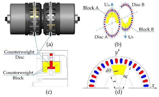
Figure 7.
Structure drawing of counterweight disc: (a) The distribution of two counterweight discs; (b) Initial state of two discs and blocks; (c) Specific view of counterweight disc; (d) Analytical diagram of counterweight block.
Taking one counterweight block as an example, it is semicircular and its mass distribution is symmetrical to the y-axis. Therefore, its center of gravity must be on the y-axis. Assuming the coordinates of the center of gravity are (0, yc), yc can be obtained by:
where R is the outer radius, r is the inner radius and θ is the center angle of the counterweight block.
The mass of the counterweight block is expressed by:
where ρ is density, B is thickness and V is volume of the counterweight block.
Because the designed counterweight block is a ladder structure, in the calculation process, it should be divided into two parts, upper and lower, with the ladder as the boundary. The specific parameters of the counterweight block are shown in Table 2. Assuming the center of gravity and mass of these two parts are yc1, yc2, mc1 and mc2, the balancing ability of the counterweight block Ub is written as:
Table 2.
Parameters of counterweight block.
Bringing these parameters into Equations (1)–(3), the balancing ability of one counterweight block is 292 g·mm. Therefore, the balancing ability of the actuator is four times that of one block, that is, 1168 g·mm. Here the counterweight block is made of brass; when the material is changed to tungsten-base alloy, the value of density can increase from 0.0085 to 0.017 and the balancing ability can be doubled to 2336 g·mm.
3.2. Balancing Accuracy
When the actuator is installed in the hollow rotor, the counterweight blocks of the two counterweight discs are in opposite directions and the compensation mass is zero. During the balancing process, through the step rotation of the two counterweight discs, the compensation mass is gradually produced. To analyze the balancing accuracy of the actuator, the step rotation procedure should be considered first.
Assuming the number of magnets on the counterweight disc is N, the center angle of each step rotation Δφ is equal to 360/N. When the compensation mass increases from 0 to the maximum value, there are three rotary methods for the two counterweight discs:
(1) The two counterweight discs approach the symmetrical axis at the same time and rotate one step every time. During the procedure, the total steps is N/4 and the compensation vector U and the variation of compensation vector ΔU can be expressed by:
where UAB is the balancing ability of each counterweight disc, φA is the initial phase of one disc and equal to 0 and φB is the initial phase of the other disc and equal to 180.
(2) The two counterweight discs approach the symmetrical axis in turn and rotate one step every time. The total steps is N/2 and these two vectors are expressed by:
where ceil and floor are two integral functions.
(3) One counterweight disc stays still while the other gradually approaches the opposite side. The total steps is also N/2 and these two vectors are expressed by:
For the actuator in the balancing experiments, the balancing ability of each counterweight disc UAB is 584 g·mm and the number of magnets N is 36; the computational results of the three rotary methods are shown in Figure 8.
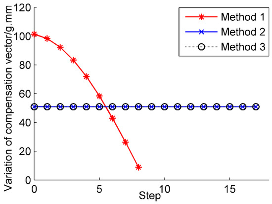
Figure 8.
Diagram of balancing accuracy analysis.
Two conclusions can be drawn from the results: (1) the variation of compensation vector for the latter two rotary methods is a fixed value, that is, ΔU for each step at any position is always 50.9 g·mm; (2) for the first rotary method, ΔU decreases from 101.4 g·mm to 8.9 g·mm, that is, when the phase difference between the two counterweight discs is larger than 900, the balancing accuracy of the first method is inferior to that of the latter two methods but when the phase difference is smaller than 900, the balancing accuracy of the first method is better. In the actual control process of the actuator, three methods should be combined and the variation range of the compensation vector is within [8.9, 50.9]. Therefore, the maximum value of ΔU can be considered as the balancing accuracy of the actuator and is equal to 50.9 g·mm.
3.3. Self-Lock Capacity
As shown in Section 2.2.3, the normal condition of the balancing actuator is the self-lock condition and the torque generated by the permanent magnets and the tooth rings is considered as self-lock torque, which keeps the counterweight disc synchronously rotating with the balancing actuator. Therefore, the self-lock torque should be checked as to whether it can prevent changes in mass distribution without control commands. Because the actuator is an axisymmetric structure and the self-lock torque is only related to the counterweight disc with permanent magnets and the tooth rings, a finite element model of these three components is established based on Maxwell software, as shown in Figure 9.
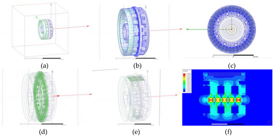
Figure 9.
Finite element analysis of self-lock torque.: (a) Finite element model; (b) Mesh generation; (c) Directional view of meshing; (d) Analysis of self-lock torque; (e)Select cross section to observe magnetic field distribution; (f) Local view of magnetic field.
After importing the 3D models of these components from SolidWorks into Maxwell, the material properties of each component were defined separately and a computational area outside the component was created. The tetrahedron element was mainly adopted during the process of meshing and the grid of counterweight disc and magnets was encrypted compared to the tooth rings. In creating parameter scan settings, the rotating angle of the counterweight disc and all permanent magnets around the central axis was defined as variable x1. Since there were 36 permanent magnets on the counterweight disc and 18 iron teeth on the tooth rings, the change period of self-locking force was about 10 degrees. Therefore, the variable x1 was chosen from 0 to 20° in order to fully display the force change of the counterweight plate and the step length was 0.5°. Before adaptive calculation, the parameters, such as maximum number of iterations and proportion of encryption cells per iteration, were respectively set and then the torque of the balancing disc and magnets relative to the central axis was calculated. To observe the distribution of magnetic field between magnets and iron teeth, a cross section was selected and the magnetic field between two pairs of magnets and iron teeth was displayed.
According to the analysis results shown in Figure 10, two conclusions can be drawn: (1) the change period of self-lock torque is equal to the central angle between two adjacent magnets and in a step-by-step process, in accordance with the sinusoidal self-lock torque changes, the maximum torque value appears at 1/4 and 3/4 step positions; and (2) with the increase of air gap δ3 between the counterweight disc and the iron teeth, the self-lock torque decreases rapidly and when the air gap is 1.0 mm, the self-lock torque is equal to 38.9 mN·m.
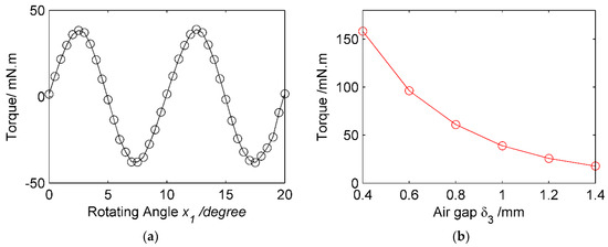
Figure 10.
Analysis results of self-lock torque. (a) Variation of torque with rotating angle x1; (b) Variation of torque with air gap δ3.
The relationship between the self-lock torque MT and the allowable acceleration α of the actuator can be written as:
where m and J are total mass and total rotary inertia of the counterweight disc respectively, R is the radius of the mass center, kSF is the designed safety factor and n is the operation speed.
From the inertia analysis of the counterweight disc and counterweight block [25], the total mass and total rotary inertia are 84.4 g and 32,000 g·mm2, respectively. The designed safety factor is set to 1.5, so the allowable acceleration of the actuator should be lower than 353 rad/s2 according to Equation (7), that is, when the operation speed of the rotor system is 4200 rpm, the starting time of the spindle should be longer than 1.25 s. If the starting time is required to be shorter, the self-lock torque can be adjusted through the decrease of the air gap δ3.
4. Control Strategy of the Balancing Actuator
4.1. Basic Principle
The initial unbalance vibration of the detected rotor system is set to with the initial unbalance vector . Because the balancing ability of two counterweight discs is equal to UAB and their initial phases are φA0 and φB0, respectively, the initial compensation vectors of two counterweight discs can be expressed by and .
After one trial step rotation, the phases of the two counterweight discs are changed to φA1 and φB1, respectively, their compensation vectors are expressed by and , and the unbalance vibration is .
Therefore, the influence coefficient vector of the detected rotor system can be written as:
and then, the initial unbalance vector is solved by:
In order to eliminate the initial unbalance vector, a compensation vector that has equal magnitude but in the opposite position compared to the initial unbalance must be generated by the balancing actuator. The compensation vector can be expressed by:
where the phase and must be within the range [0, 360).
The relationship between the two compensation vectors of the counterweight discs and the resultant compensation vector during the balancing process are shown in Figure 11. In the triangle formed by these three vectors, the magnitudes of the two compensation vectors are equal, so it is an isosceles triangle and the angles between the two compensation vectors and the resultant compensation vector are the same. According to the cosine theorem, the included angle is obtained by:
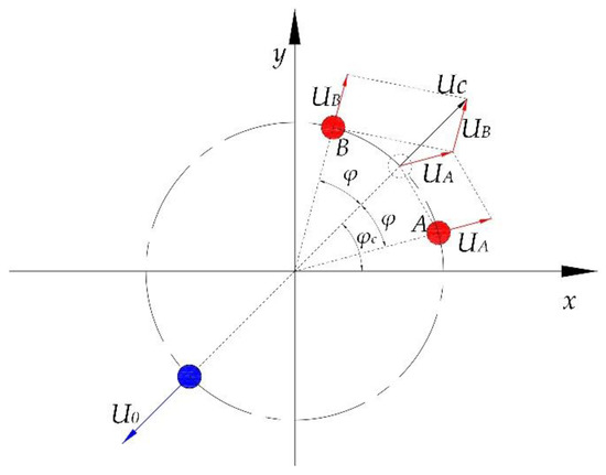
Figure 11.
Control principle of the active balancing system.
To eliminate the initial unbalance vector, the two counterweight discs should step rotate to their phases and the phase values are given by
Therefore, when the initial vibration of the detected rotor is achieved by the data collection unit, the new positions of the two counterweight discs can be solved by Equations (8)–(12).
4.2. Phase Detection of Counterweight Discs
To control the balancing actuator, the phases of the two counterweight discs should be detected and the distribution of the corresponding sensors is shown in Figure 12. Considering several factors, such as response speed and installation size, the unipolar Hall-effect sensor is chosen for phase detection. The detection principle is based on the Hall Effect, that is, each time a magnetic field passes through the sensor, the sensor outputs a pulse voltage. Therefore, three Hall sensors are needed in the stationary part of the actuator, while three permanent magnets are installed in the rotary part to generate magnetic field and a permanent magnet corresponds to the Hall sensor. Two of the permanent magnets are fixed on the counterweight blocks of the counterweight discs and the other magnet is fixed on the cover plate of the rotary part.
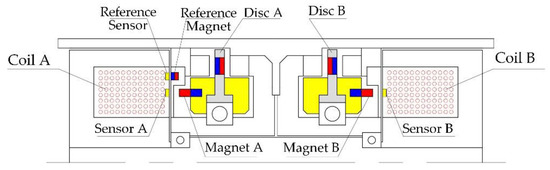
Figure 12.
Installation position of Hall sensor and permanent magnets.
When the rotary part of the actuator synchronously rotates with the rotor system, for each circle of the rotary part, the magnetic field generated by a magnet passes through its Hall sensor one time and three Hall sensors produce three pulse voltage signals. Because the magnet fixed on the cover plate is still relative to the rotor, its corresponding pulse signal is considered as the reference signal and is also the speed signal of the rotor. The other two voltage signals are considered as the position signals of the two counterweight discs. The three pulse signals are shown in Figure 13. Through the phase difference calculation between the position signals and the reference signal, the phase of the two counterweight discs can be detected by Equation (13):
where τ is the rotational period of the rotor, τ1 and τ2 are the time difference between the position signals and the reference signal and Δφ is the phase of each step rotation. Due to the interference signals and installation errors of magnets and Hall sensors, the integral function Round() is used to modify the detection results.
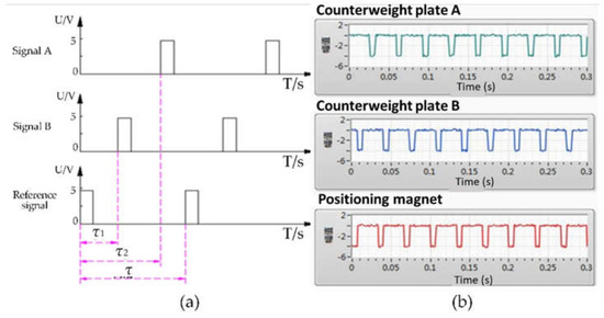
Figure 13.
Three pulse signals from Hall sensors: (a) Schematic diagram of the signals; (b) Signal collection results.
4.3. Control Program
When the control unit forms control commands according to the unbalance vibration of the machine tool spindle, the power supply unit is instructed to form the corresponding voltage signals. According to the principle of step rotation, the actuator needs a magnetic field with alternating directions during the balancing operation, so the voltage signals supplied by the power supply unit must alternate between positive and negative voltage.
To ensure normal operation of the power supply unit, four DC-DC solid state relays and an I/O module with four output channels are adopted to cooperate with the power supply unit, each state relay corresponding to an output channel of the I/O module and the four output channels control the opening and closing of the four state relays. Four output channels and corresponding state relays are divided into two groups and each group corresponds to a coil of the actuator. When commands are not required, all output channels are normally open, the control circuit is disconnected, the state relays are not working and the power supply unit has no voltage output; when the control unit requires a driving coil to operate, the two output channels corresponding to the driving coil and state relays begin to close alternately, producing positive and negative pulse voltage signals. The final voltage signal received by the driving coil is the composite voltage of the two pulse voltage signals, as shown in Figure 14. Due to the effects of coil anti-electromotive force, there is a back voltage behind each working voltage. Because the width of the back voltage is quite shorter than that of the working voltage, certain circuits are used to limit its maximum value but the effect is neglected in the control program.
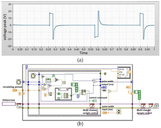
Figure 14.
Control program of the balancing actuator: (a) Voltage signal of the actuator; (b) Codes of the control program.
Based on the LabVIEW platform, a control program was developed and its codes are shown in Figure 14. Through debugging of the program, two conclusions can be drawn: (1) when the commands are sent by the I/O module, the corresponding state relays can be opened correctly and the voltage signals can be correctly generated; and (2) when the width of the pulse voltage signal increases from 30 ms to 200 ms by 10 ms steps, the program runs 1000 times at each step and the total cycle number is 18,000 times. The debugging results show that the control accuracy of the program is always within 1 ms, which can meet the control requirements of the balancing actuator.
5. Experiments
An actuator was produced to verify the principle of step rotation, as shown in Figure 15. The outer diameter and width of the rotatory part are 66 mm and 60 mm and the outer diameter and width of the coil case are 60 mm and 26 mm, respectively. So the maximum diameter of the actuator is 66 mm and the total length is 110 mm. The balancing ability of the actuator is about 1160 g·mm. To drive the actuator, 0.8 mm enameled wire is used to make driving coils and the coils are turned 400 times.
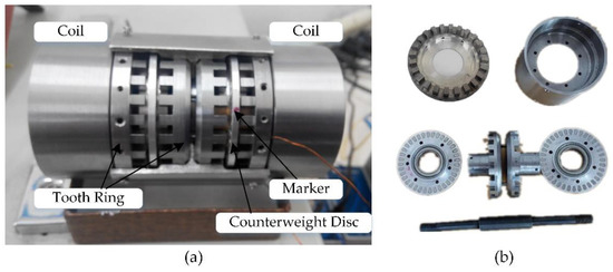
Figure 15.
Picture of electromagnetic ring actuator: (a) Overall structure; (b) component structure.
5.1. Function Experiments
5.1.1. Magnetic Circuit Measurement
The magnetic field between the rotary part and the stationary part of the actuator was measured by a digital Gauss meter with a measuring range of 0–2000 mT and resolution of 0.1 mT. In order to install the measuring probe, the air gap between the rotary part and the stationary part was extended to 2 mm and a Gauss Hall probe was adopted to measure the magnetic field intensity of the actuator with different driving voltages. Before measurement, the insertion depth of the Hall probe was changed. By observing the Gauss meter reading when the driving coil was not energized, the position of the maximum magnetic field intensity was found. At the end of each excitation operation, the Gauss meter reading had to be observed again to ensure that the Hall probe was in the position of maximum magnetic field intensity during the whole measurement process. During the experiment, the power supply voltage of the coil was adjusted from 12 V to 23 V and a change of maximum magnetic field intensity was observed, as shown in Figure 16. Two conclusions can be drawn from the experimental results: (1) when the driving voltage was adjusted in the range of 12–23 V, the relationship between the magnetic field intensity and the driving voltage was approximately linear and with the increased driving voltage, the magnetic field intensity in the actuator increased synchronously; and (2) when the supply voltage was adjusted in the range of 23 V, the magnetic field intensity increased monotonously all the time and there was no saturation of magnetic field intensity in the magnetic circuit, verifying the effectiveness of the internal magnetic circuit design of the actuator.
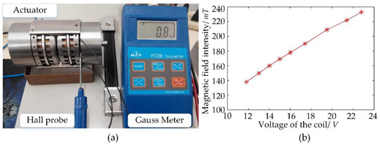
Figure 16.
Magnetic field measurement of the actuator: (a) Experimental devices; (b) Measurement results.
5.1.2. Step Rotation Experiment
Before the experiment, a marker was made on each counterweight disc as the initial position of step rotation, shown in Figure 15. Two 350 W, 15 V DC power supplies were selected to supply power for the actuator and their output voltage could be adjusted from 12 V to 18 V. Once the voltage of the power supply unit was determined, the width of the pulse voltage, the time interval between positive and negative voltages and the output sequence of positive and negative voltages could be adjusted by the control program, shown in Figure 17. From the results, we know that the actuator can work normally with 15 V–18 V and the width of the pulse voltage can range from 24 to 30 ms at 18 V.
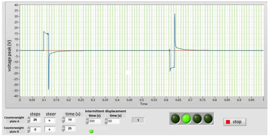
Figure 17.
Control program of Step rotation experiments.
5.2. Active Balancing Experiments
The balancing experimental devices was constructed as shown in Figure 18. A Siemens stepping motor was chosen to drive the machine tool spindle by belt connection and the maximum rotating speed was 4500 rpm. The designed balancing actuator was installed in the hollow rotor of the spindle and the displacement sensor was used to monitor the vibration of the rotor system. The data collection unit comprised a cDAQ Ethernet chassis with two data acquisition modules and a digital output module. The two data acquisition modules were used to measure the vibration signal, rotational speed signal and counterweight disc positioning signals and the digital output module was used to send out control commands. A PC was selected as the control unit to analyze the vibration signal, calculate the initial unbalance and generate control commands. The power supply unit mainly contained two 15V DC power supplies and four DC-DC solid state relays to generate positive and negative alternating voltage signals.
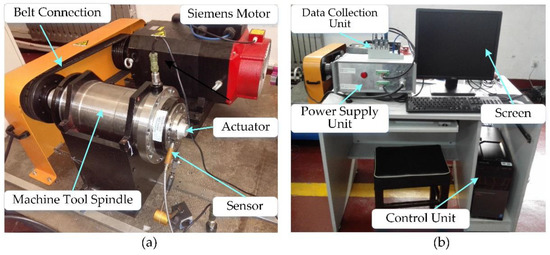
Figure 18.
Overall diagram of experimental device: (a) Balancing actuator and the rotor system; (b) Other components of the balancing system.
Restricted by the conditions of the experimental site, the balancing experiments can only be carried out at the speed of 3600 rpm or lower. Meanwhile, the difficulty of active balancing was raised with the increase of balancing speed, so the balancing results at 3600 rpm were emphatically introduced.
First, the step rotation experiment was repeated when the actuator synchronously rotated with the rotor. The results in Figure 19 show that the two counterweight discs of the balancing actuator can be stepped in the same direction and the opposite direction according to the commands of the control unit and there was no error during the step-by-step rotation of the whole cycle. The step-by-step test process was repeated for 50 cycles, that is, each counterweight disc rotated 1800 times step by step but there was still no error. Therefore, the step error of the actuator was less than 1/1000.
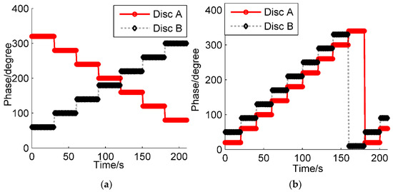
Figure 19.
Step rotation experiments of the actuator: (a) In the opposite direction; (b) In the same direction.
The change of unbalance vibration during the balancing process is shown in Figure 20, where the blue solid line and red dotted line represent the unbalance vibration amplitude and phase, respectively. The initial unbalance amplitude was about 3.2 µm and through the active balancing within 20 s, it was reduced to below 0.4 μm with an 87.5% decrease. Before the balancing process, the initial unbalance phase was stable and about 140 degree. During the balancing process, the unbalance phase was changed a little and the range was 40 degree. At the end of the balancing process, the amplitude of the unbalance vibration was so small that the vibration phase had a large range of fluctuations. Because the fluctuations of phase was mainly determined by the accuracy of the experimental device itself and had little effect on rotor system, it was ignored and the balancing process was finished.
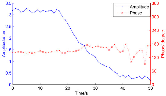
Figure 20.
Active balancing experiment results of the actuator.
6. Conclusions
This paper proposes a novel electromagnetic-ring actuator integrated into the hollow rotor of a machine tool spindle. The working principle of the actuator is described in detail and the performance of the actuator is analyzed, including the balancing ability, balancing accuracy and self-lock capacity. A phase detection and control program is developed to control the normal operation of the actuator. To confirm the effectiveness of the novel actuator, function experiments and active balancing experiments were conducted. During the function experiments, the magnetic circuit of the actuator was statically measured and the requirements for pulse voltage were determined. Then the designed actuator was installed in the hollow rotor of the spindle and the balancing experiments were conducted at 3600 rpm. The experimental results show that the counterweight disc could step rotate 1800 times with no error, the actuator could reduce the unbalance vibration of the machine tool spindle from 3.2 μm to below 0.4 µm within 20 s and the amount of vibration decreased by 87.5%. In further research, the actuator will be applied to the actual machine tool and the improvement of the balancing actuator in machining accuracy and efficiency will be studied. With the development of intelligent spindle and Industry 4.0 technology, active balancing actuators will have broader market prospects.
7. Patents
As a result of the work reported in this manuscript, the authors applied for a national invention patent (CN201610811273.3) from the Chinese Patent Office and the patent was authorized in June 2018.
Author Contributions
Conceptualization, X.P. and H.W.; Data curation, X.P. and X.H.; Formal analysis, X.H.; Methodology, X.P. and H.W.; Project administration, Z.J.; Software, K.W.; Supervision, J.G.; Writing–original draft, X.P. and K.W.; Writing–review and editing, J.G. and Z.J.
Funding
This work was supported by the National Natural Science Foundation of China (Grant No. 51875031), the Youth Backbone Personal Project of Beijing (Grant No.2017000020124G018) and the Fundamental Research Funds for Central Universities (Grant Nos. ZY1618 and JD1813).
Conflicts of Interest
The authors declare no conflict of interest.
List of Symbols
| yc | center of gravity on y axis | φc | phase of compensation vector |
| R | outer radius of counterweight block | N | number of magnets on disc |
| r | inner radius of counterweight block | x1 | rotating angle of counterweight disc |
| UAB | balancing ability of each counter-weight disc | δ3 | air gap between counterweight disc and iron teeth |
| mc | mass of counterweight block | MT | self-lock torque of counterweight disc |
| φA | phase of counterweight disc A | αn | allowable acceleration of actuator |
| φB | phase of counterweight disc B | V0 | amplitude of initial unbalance vibration |
| Δφ | center angle of each step rotation | V1 | amplitude of vibration after step rotation |
| ΔU | variation of compensation vector | k | influence coefficient of rotor system |
| Uc | amplitude of compensation vector | τ | rotational period of rotor system |
References
- Cao, H.R.; Zhang, X.W.; Chen, X.F. The concept and progress of intelligent spindles: A review. Int. J. Mach. Tools Manuf. 2017, 112, 21–52. [Google Scholar] [CrossRef]
- Lee, J.; Kao, H.A.; Yang, S. Service innovation and smart analytics for Industry 4.0 and big data environment. Procedia CIRP 2014, 16, 3–8. [Google Scholar] [CrossRef]
- Zaeh, M.F.; Kleinwort, R.; Fagerer, P.; Altintas, Y. Automatic tuning of active vibration control systems using inertial actuators. CIRP Ann. Manuf. Technol. 2017, 66, 365–368. [Google Scholar] [CrossRef]
- Kleinwort, R.; Schweizer, M.; Zaeh, M.F. Comparison of Different Control Strategies for Active Damping of Heavy Duty Milling Operations. Procedia CIRP 2016, 46, 396–399. [Google Scholar] [CrossRef]
- Lee, R.M.; Chen, T.C. Adaptive Control of Active Magnetic Bearing against Milling Dynamics. Appl. Sci. 2016, 6, 52. [Google Scholar] [CrossRef]
- Zhang, X.W.; Wang, C.X.; Gao, R.X.; Yan, R.Q.; Chen, X.F.; Wang, S.B. A Novel Hybrid Error Criterion-Based Active Control Method for on-Line Milling Vibration Suppression with Piezoelectric Actuators and Sensors. Sensors 2016, 16, 68. [Google Scholar] [CrossRef] [PubMed]
- Uhlmann, E.; Saoji, M.; Peukert, B. Utilization of Thermal Energy to Compensate Quasi-static Deformations in Modular Machine Tool Frames. Procedia CIRP 2016, 40, 1–6. [Google Scholar] [CrossRef]
- Li, Y.; Zhao, W.H.; Lan, S.H.; Ni, J.; Lu, B.H. A review on spindle thermal error compensation in machine tools. Int. J. Mach. Tools Manuf. 2015, 95, 20–38. [Google Scholar] [CrossRef]
- Hu, G.F.; Zhang, D.W.; Gao, W.G.; Chen, Y.; Tian, Y.L. Study on variable pressure/position preload spindle-bearing system by using piezoelectric actuators under close-loop control. Int. J. Mach. Tools Manuf. 2018, 125, 68–88. [Google Scholar] [CrossRef]
- Hwang, Y.K.; Lee, C.M. Development of a newly structured variable preload control device for a spindle rolling bearing by using an electromagnet. Int. J. Mach. Tools Manuf. 2010, 50, 253–259. [Google Scholar] [CrossRef]
- Pan, X.; Wu, H.Q.; Gao, J.J.; Wang, W.M. New Liquid Transfer Active Balancing System Using Compressed Air for Grinding Machine. ASME J. Vib. Acoust. 2015, 137, 011002. [Google Scholar] [CrossRef]
- Zhang, S.; Wang, Y.; Zhang, Z. Online Dynamic Balance Technology for High Speed Spindle Based on Gain Parameter Adaption and Scheduling Control. Appl. Sci. 2018, 8, 917. [Google Scholar] [CrossRef]
- Deepthikumar, M.B.; Sekhar, A.S.; Srikanthan, M.R. Modal balancing of flexible rotors with bow and distributed unbalance. J. Sound Vib. 2013, 24, 6216–6233. [Google Scholar] [CrossRef]
- Liao, Y.; Lang, G.; Wu, F.; Qu, L. An Improvement to Holospectrum based field balancing method by reselection of balancing object. J. Vib. Acoust. Trans. ASME. 2009, 131, 987–1002. [Google Scholar] [CrossRef]
- Xu, X.B.; Chen, S.; Zhang, Y. Automatic balancing of AMB systems using plural notch filter and adptive synchronous compensation. J. Sound Vib. 2016, 374, 29–42. [Google Scholar] [CrossRef]
- Ma, S.L.; Pei, S.Y.; Wang, L.; Xu, H. A Novel Active Online Electromagnetic Balancing Method—Principle and Structure Analysis. J. Vib. Acoust. Trans. ASME 2012, 134, 034503. [Google Scholar] [CrossRef]
- Zhang, Y.; Mei, X.S.; Zou, D.L.; Xu, M.X.; Wang, L. Design and Performance Analysis of Hydrojet-typed Balancing Device for High-Speed Machine Tool Spindle. J. XI’AN Jiaotong Univ. 2013, 47, 13–17. [Google Scholar] [CrossRef]
- Pan, X.; Wu, H.Q.; Gao, J.J. Rotating Machinery Targeting Self-recovery Regulation System for Imbalance Vibration Fault with Liquid-transfer Active Balancing Device. Chin. J. Mech. Eng. 2015, 51, 146–152. [Google Scholar] [CrossRef]
- Zhang, X.N.; Liu, X.; Zhao, H. New Active Online Balancing Method for Grinding Wheel Using Liquid Injection and Free Dripping. J. Vib. Acoust. Trans. ASME 2018, 140, 031001. [Google Scholar] [CrossRef]
- Hredzak, B.; Guo, G.X. New Electromechanical Balancing Device for Active Imbalance Compensation. J. Sound Vib. 2006, 294, 737–751. [Google Scholar] [CrossRef]
- Moon, J.D.; Kim, B.S. Development of the active balancing device for high-speed spindle system using influence coefficients. Int. J. Mach. Tools Manuf. 2006, 46, 978–987. [Google Scholar] [CrossRef]
- Fan, H.; Jing, M.; Wang, R.; Liu, H.; Zhi, J. New electromagnetic ring balancer for active imbalance compensation of rotating machinery. J. Sound Vib. 2014, 333, 3837–3858. [Google Scholar] [CrossRef]
- Hofmann Company. Active Balancing. Available online: http//www.hofmann-balancing.com/products/active-balancing-systems/ring-balancer-ab-9000.html (accessed on 20 June 2018).
- Schmitt Company. SBS Automatic Balancing System. Available online: http//www.schmitteurope.com/Balancers/SBS-automatic.html (accessed on 20 June 2018).
- Pan, X. Research on Priciple and Methods of Pneumatic Liquid Type and Electromagnetic Ring Type Auto-balancing Systems for High-end Machine Tools. Ph.D. Thesis, Beijing University of Chemical Technology, Beijing, China, 2015. [Google Scholar]
© 2019 by the authors. Licensee MDPI, Basel, Switzerland. This article is an open access article distributed under the terms and conditions of the Creative Commons Attribution (CC BY) license (http://creativecommons.org/licenses/by/4.0/).