Investigation of Hydrodynamic Forces for Floating Offshore Wind Turbines on Spar Buoys and Tension Leg Platforms with the Mooring Systems in Waves


Abstract
1. Introduction
2. Platform Configuration and Mooring Layout
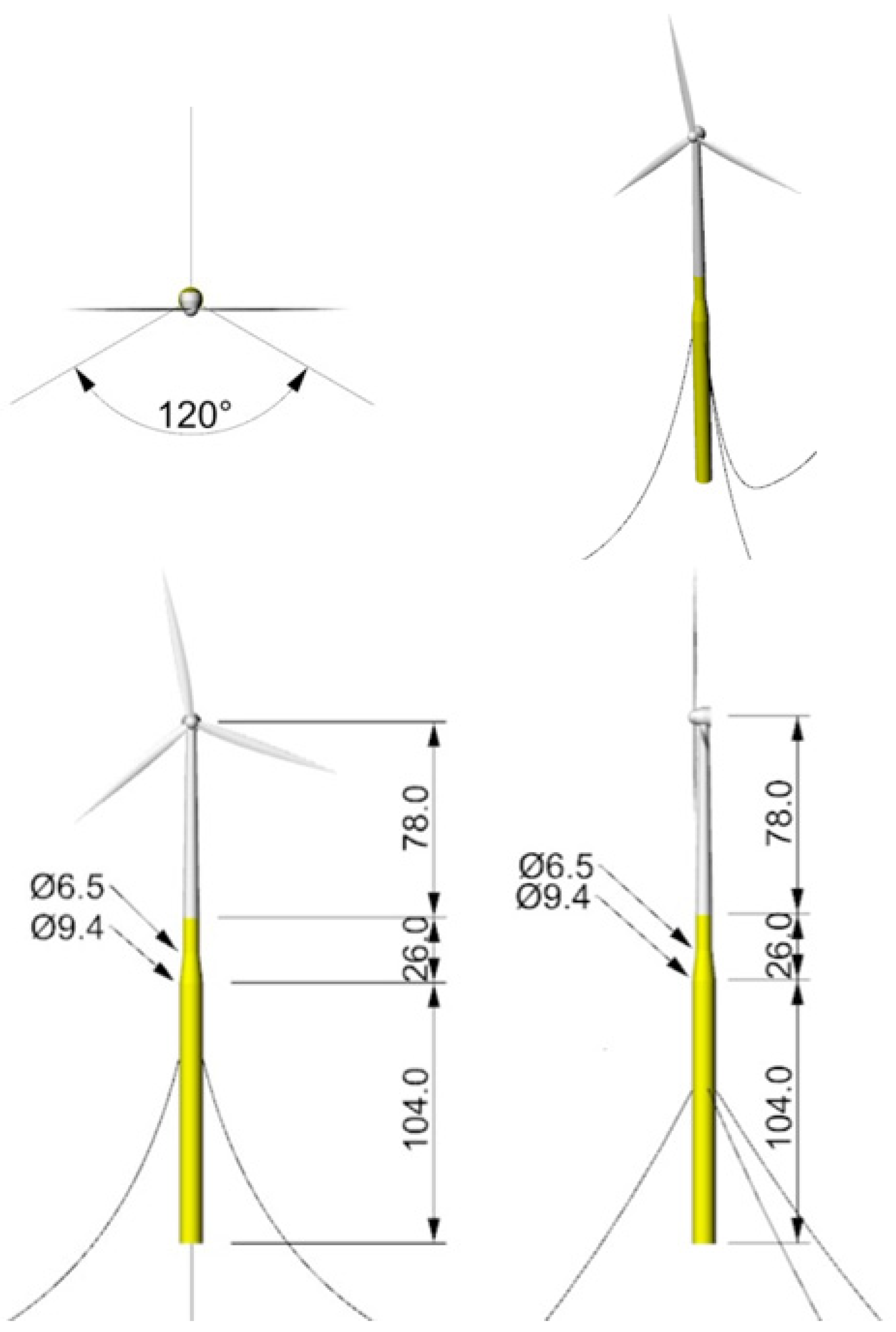
2.1. OC3-Hywind Spar/UMaine-Hywind Spar
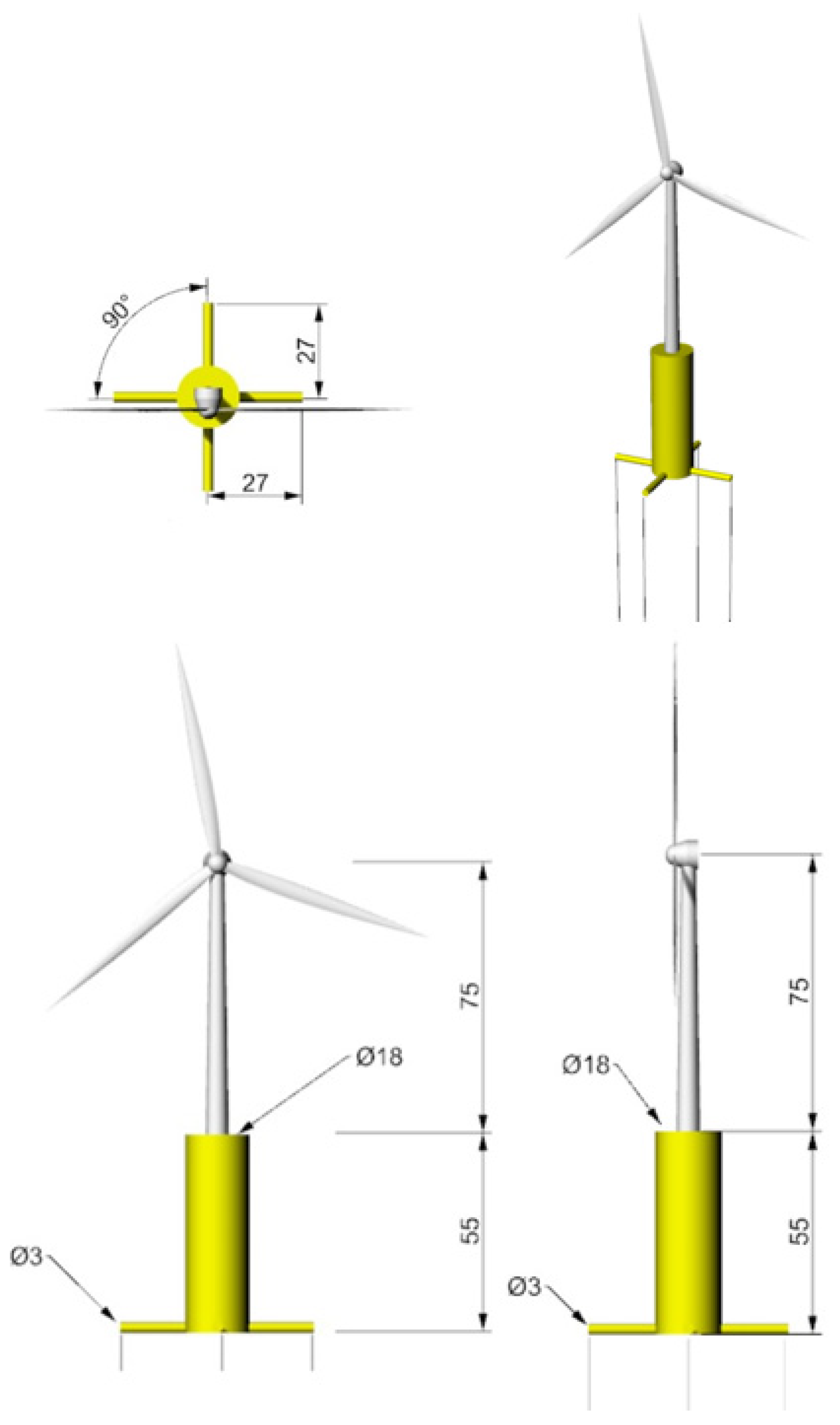
2.2. MIT/NREL TLP
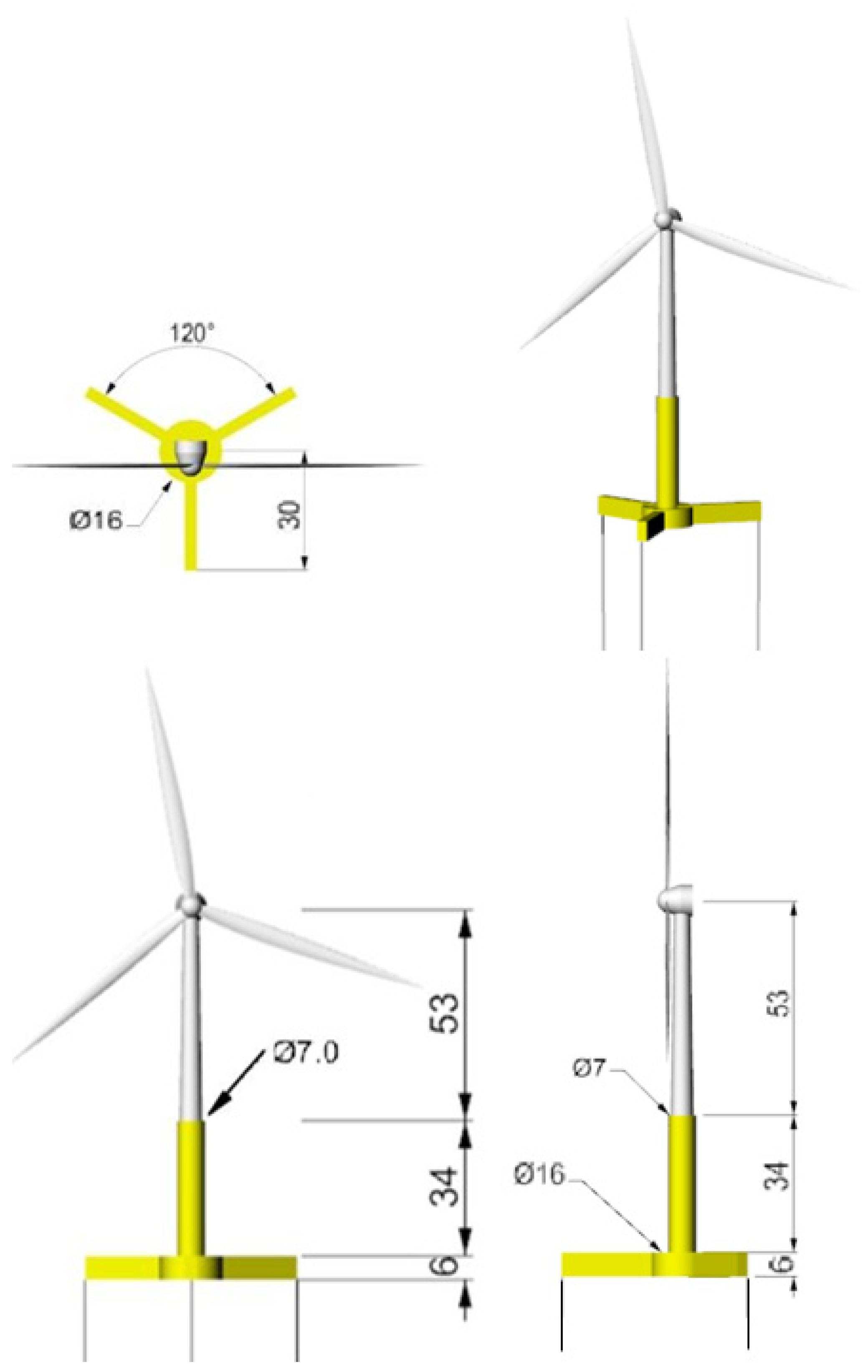
2.3. UMaine-Hywind TLP
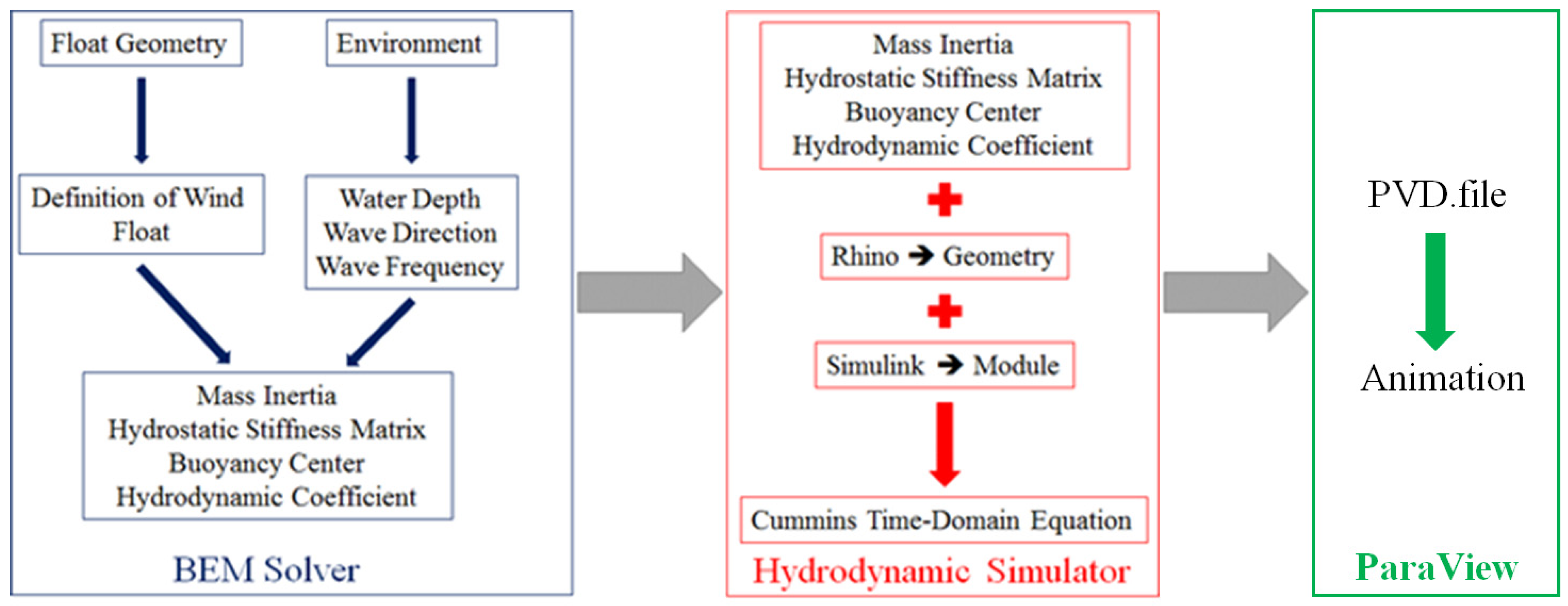
3. Structure of Modular System
4. Mathematical Model
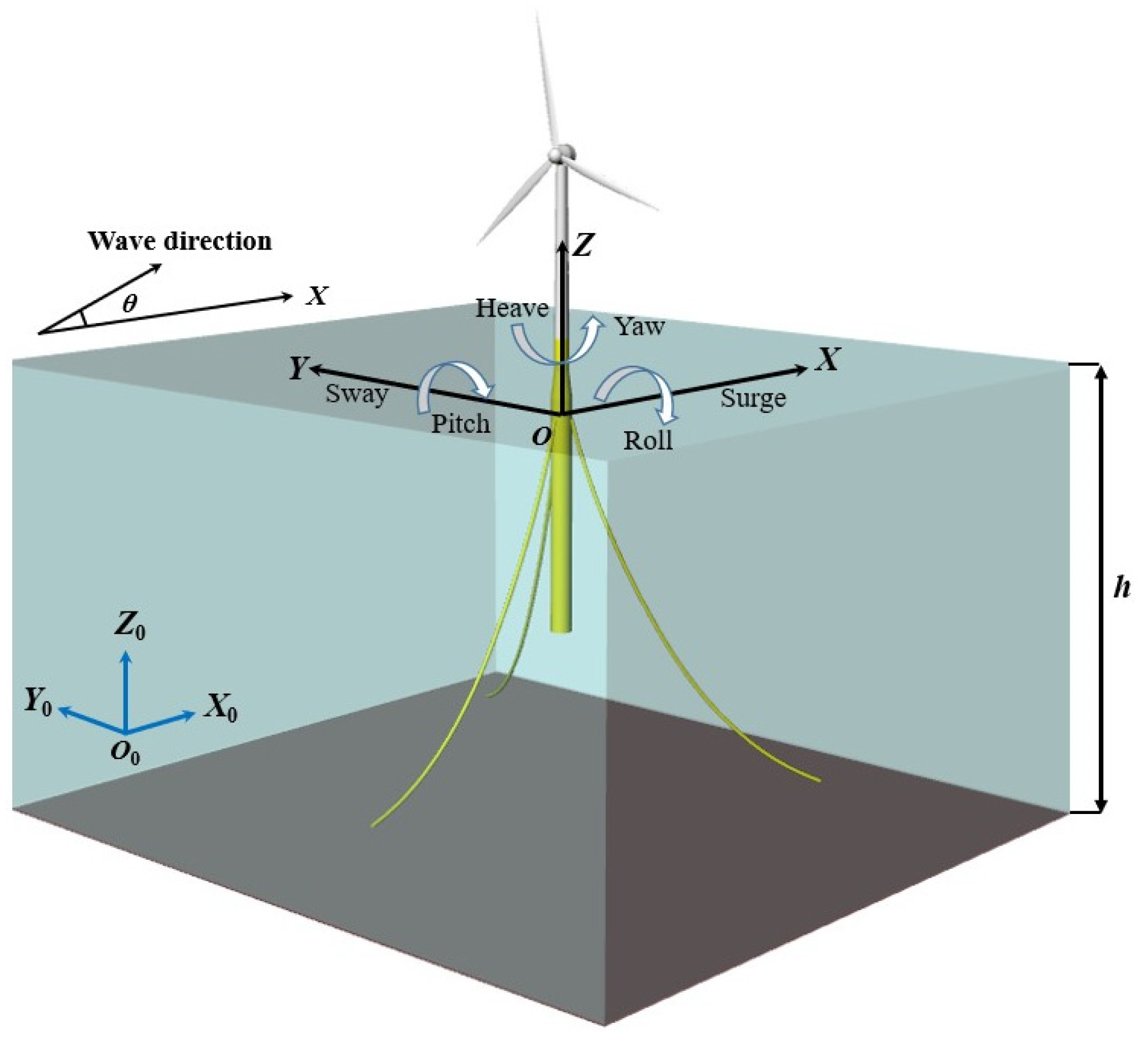
4.1. Coordinate System
4.2. Governing Equation
4.3. Cummins Time Domain Equation
4.4. Wave Spectrum
5. Analysis of Hydrodynamic Coefficients
5.1. OC3-Hywind Spar/UMaine-Hywind Spar
5.2. MIT/NREL TLP
5.3. UMaine TLP
6. Dynamic Responses of Floating OWTs
6.1. OC3-Hywind Spar
6.2. UMaine-Hywind Spar
6.3. MIT/NREL TLP
6.4. UMaine TLP
7. Conclusions
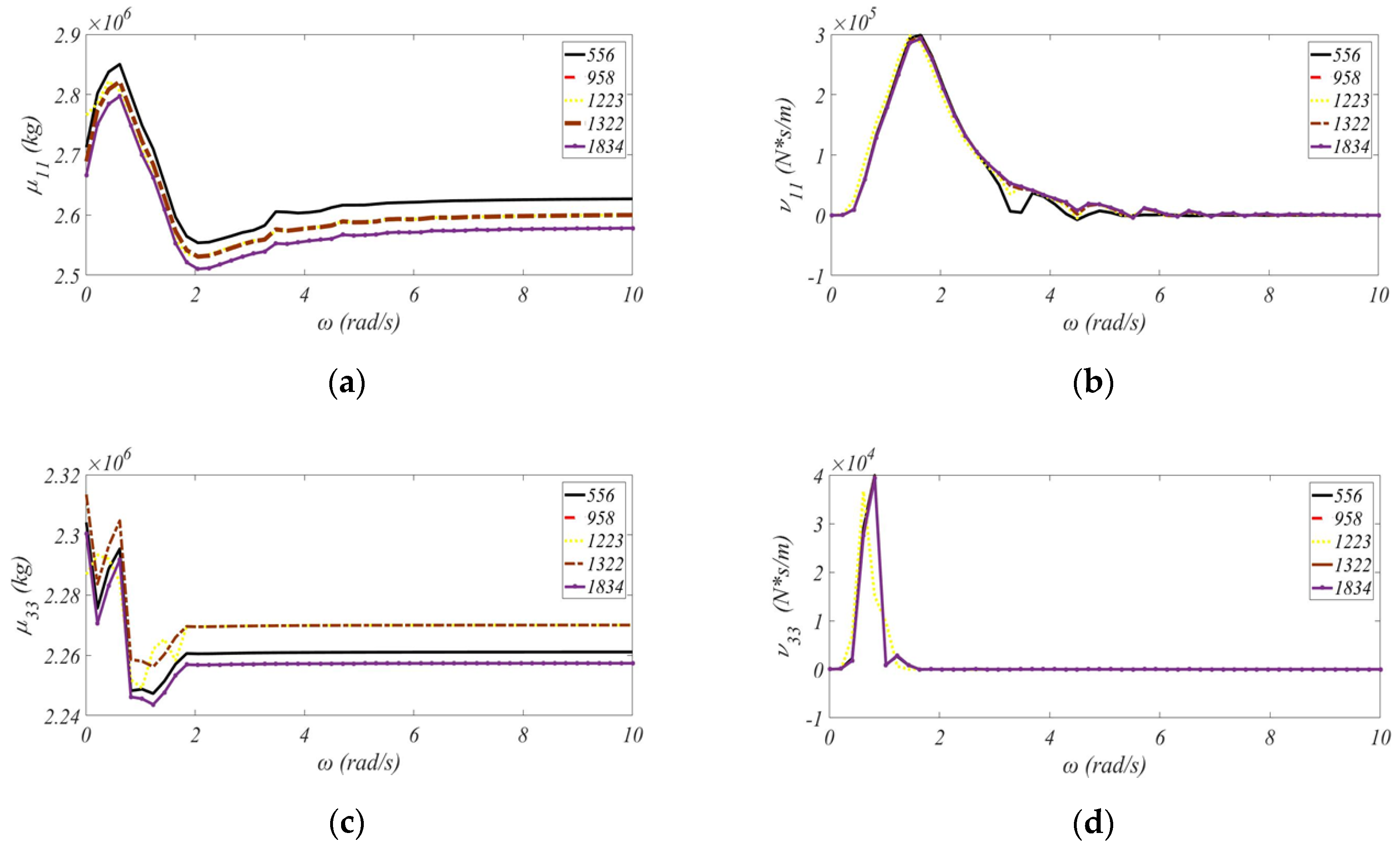
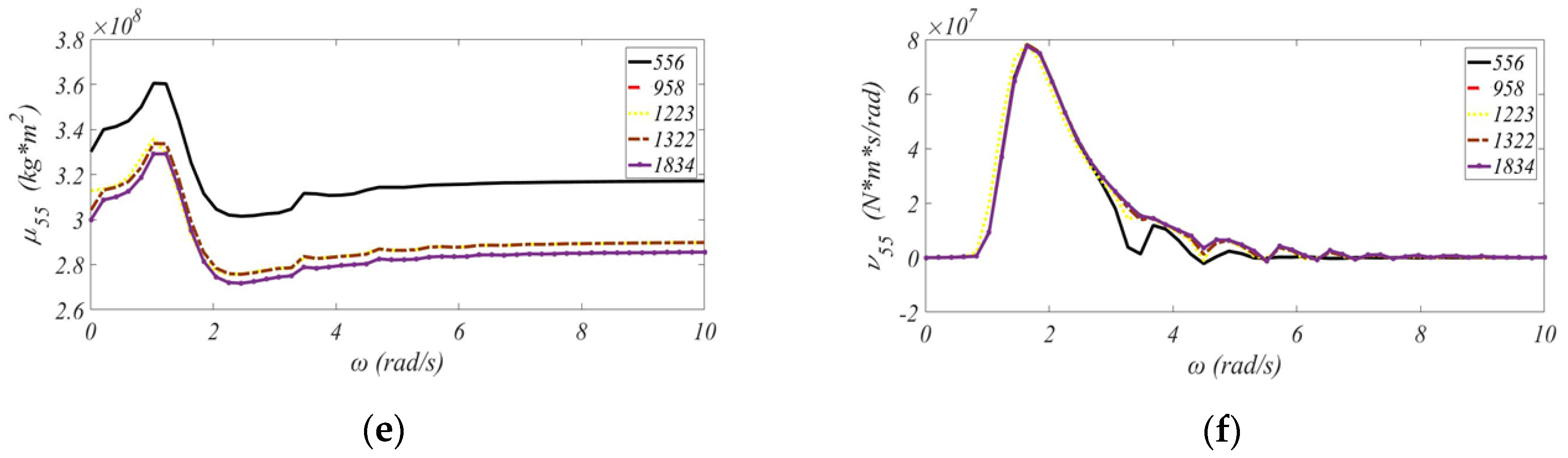
- For the spar buoy concept, the decrease in water depth results in larger added-mass coefficient in the pitch mode 𝜇55, but causes smaller radiation damping coefficient in the pitch mode 𝜈55.
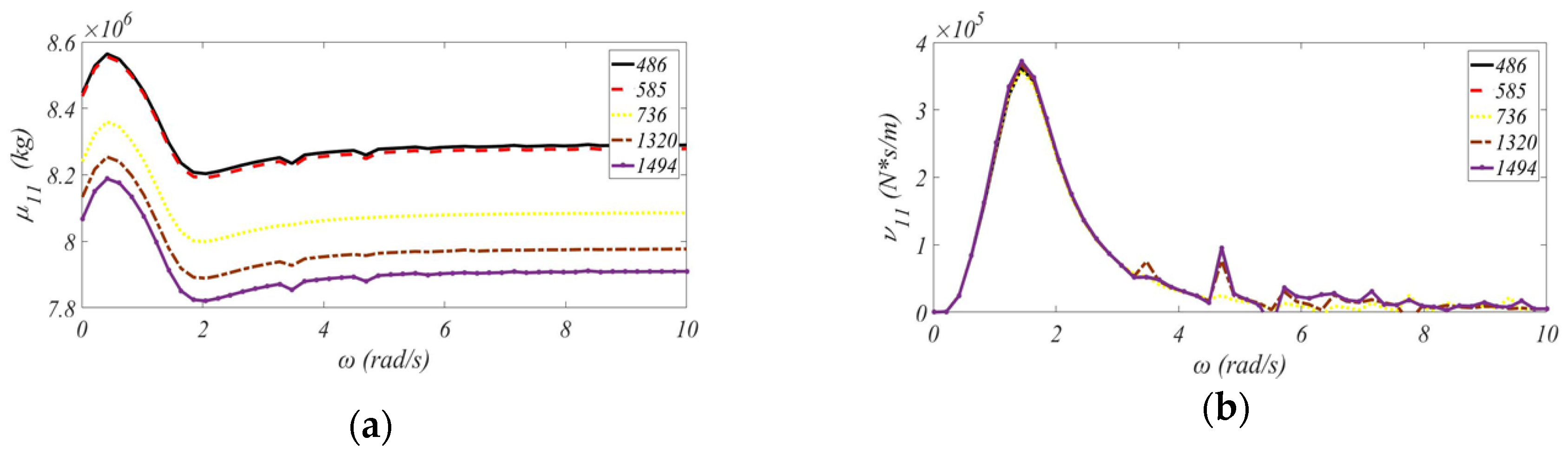
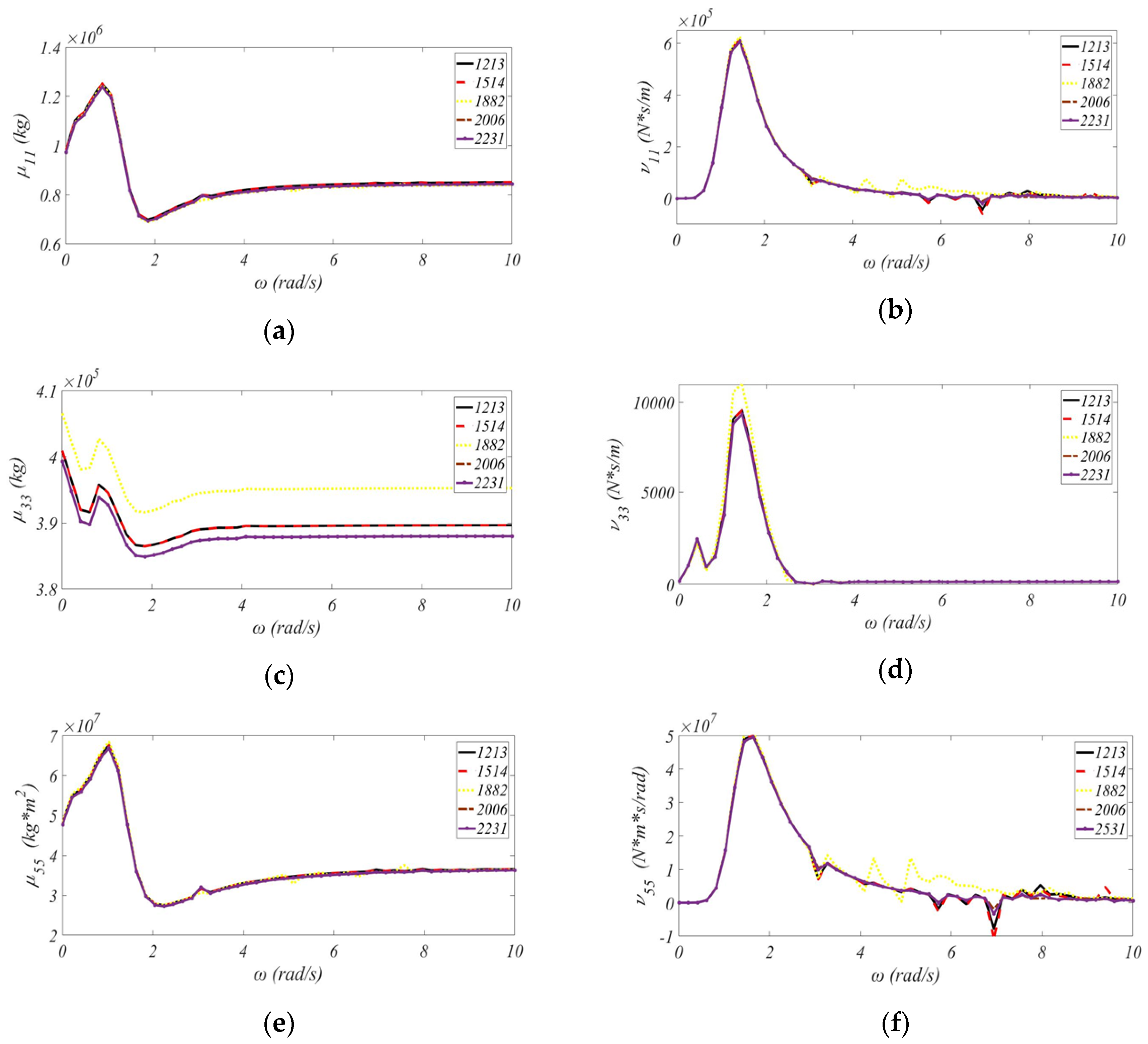
- For the design of the MIT/NREL TLP, the larger displaced water and the wetted surface in the surge and pitch modes would lead to higher added-mass coefficients 𝜇11 and 𝜇55 than the value in the heave mode 𝜇33.
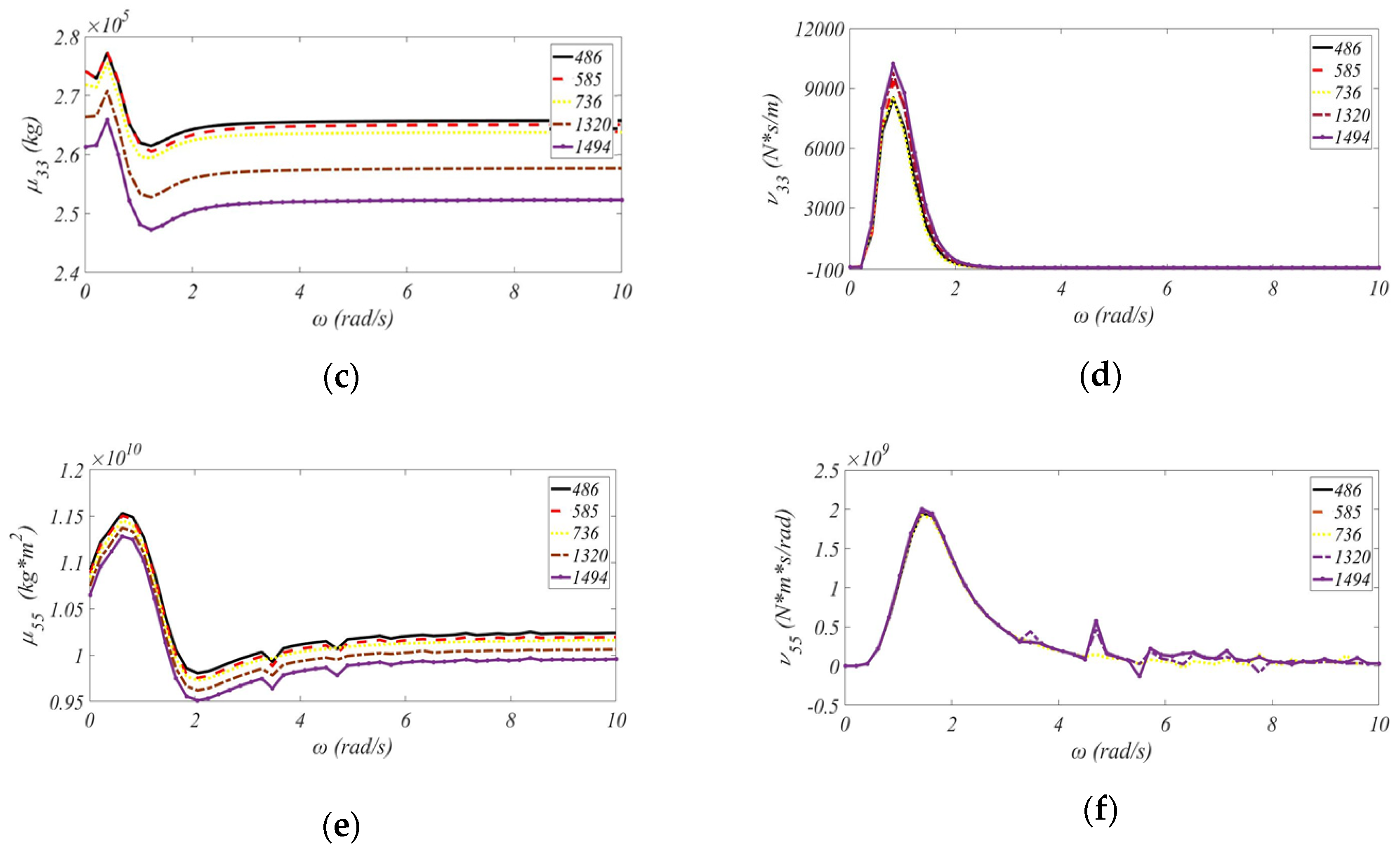
- Compared to the design of the MIT/NREL TLP, the large radius and diameter of the pontoon for the UMaine TLP would produce high value of the added-mass coefficient in the pitch mode 𝜇55. The increases in the radius and diameter of the pontoon are accompanied with low resonance frequency of the radiation damping coefficient in the surge mode, whereas the decrease in the diameter of the column is related to low resonance frequency of the heave coefficient.
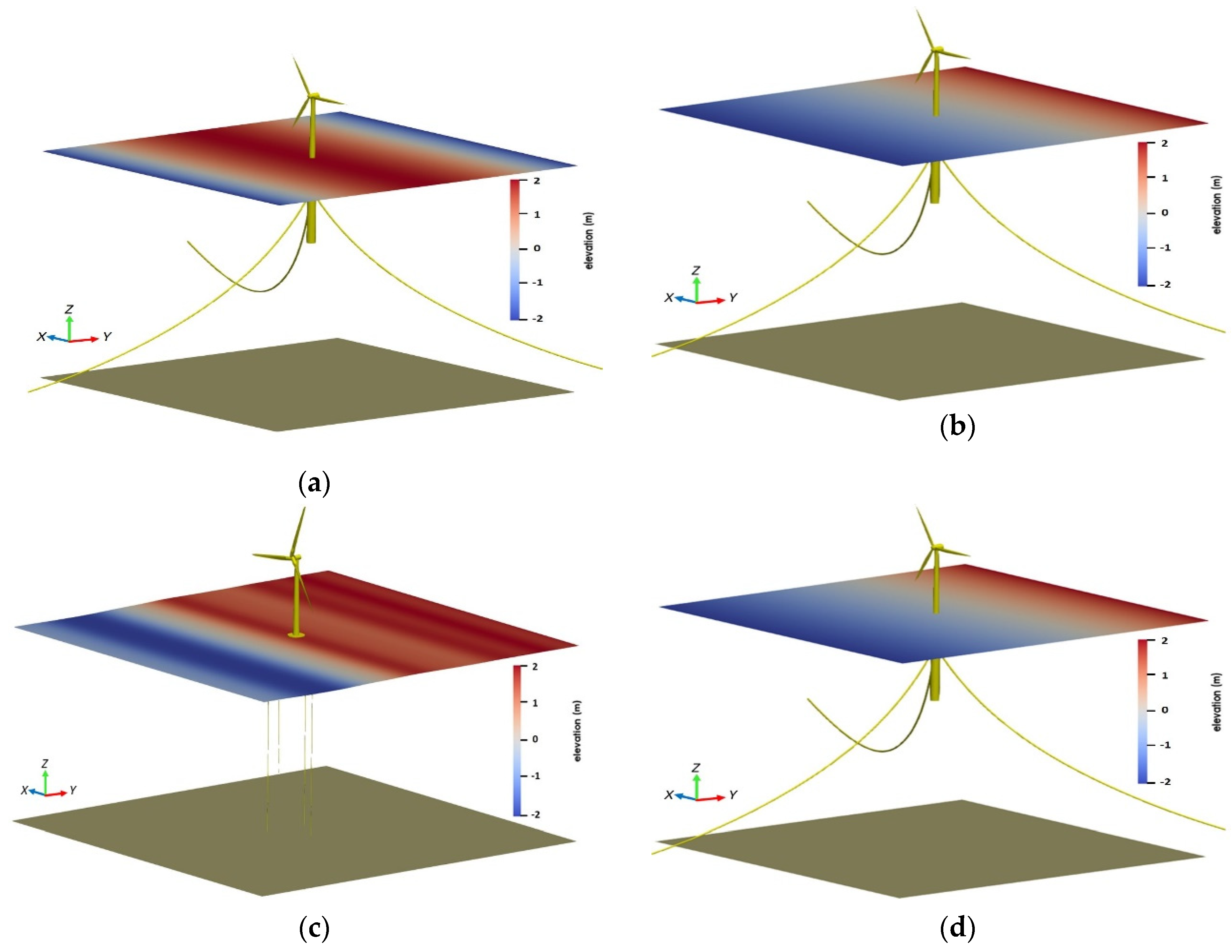
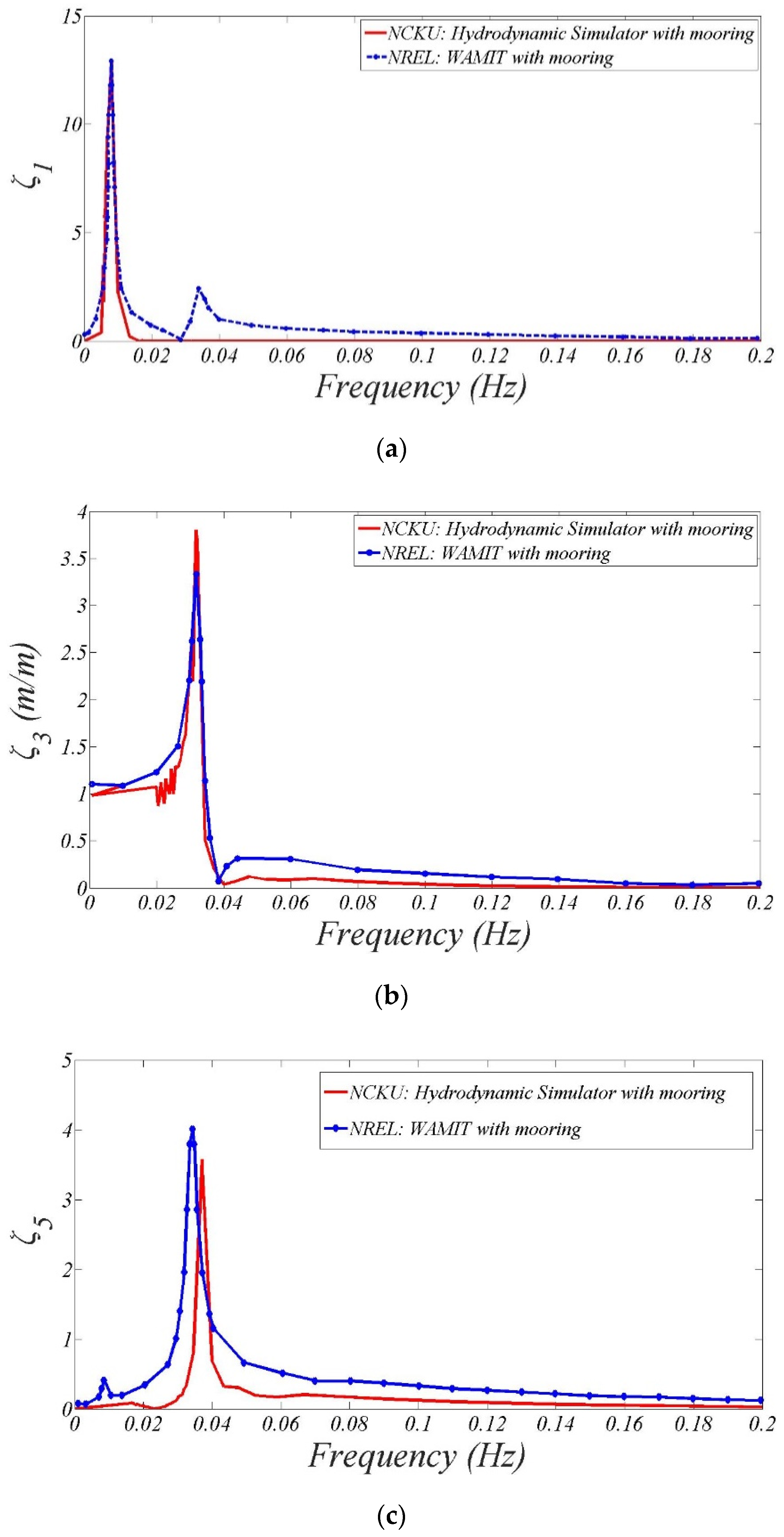
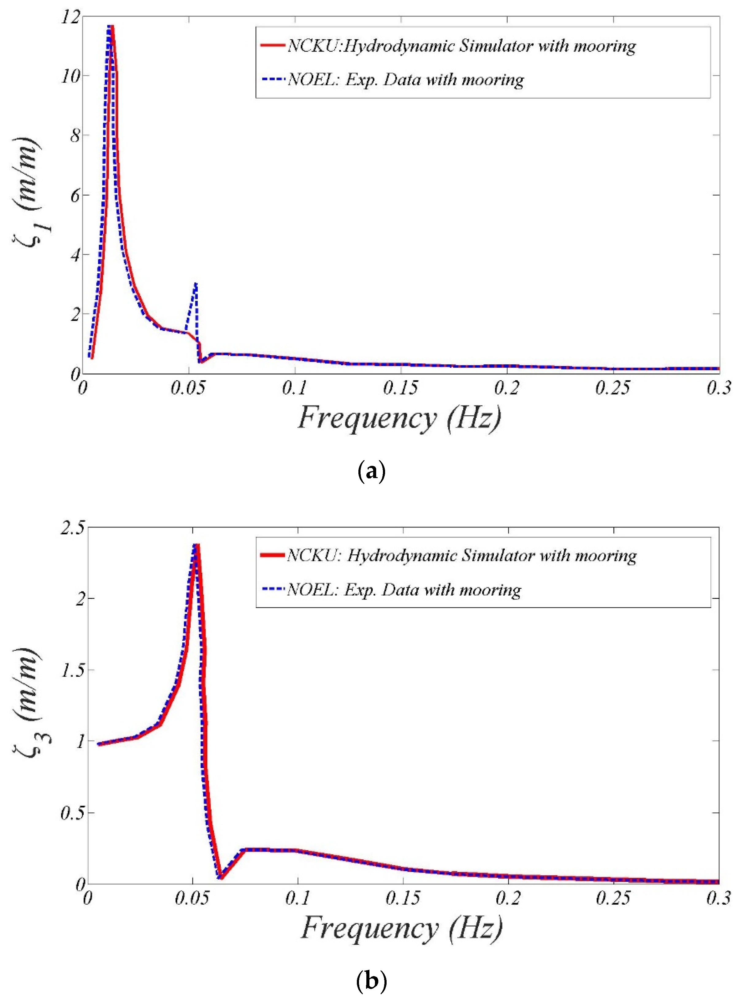
- Due to the influence of unstretched mooring lines parallel to the seabed on the OC3-Hywind spar, the catenary mooring system has considerable contribution to the surge RAO, but provides for less effect on the heave RAO.
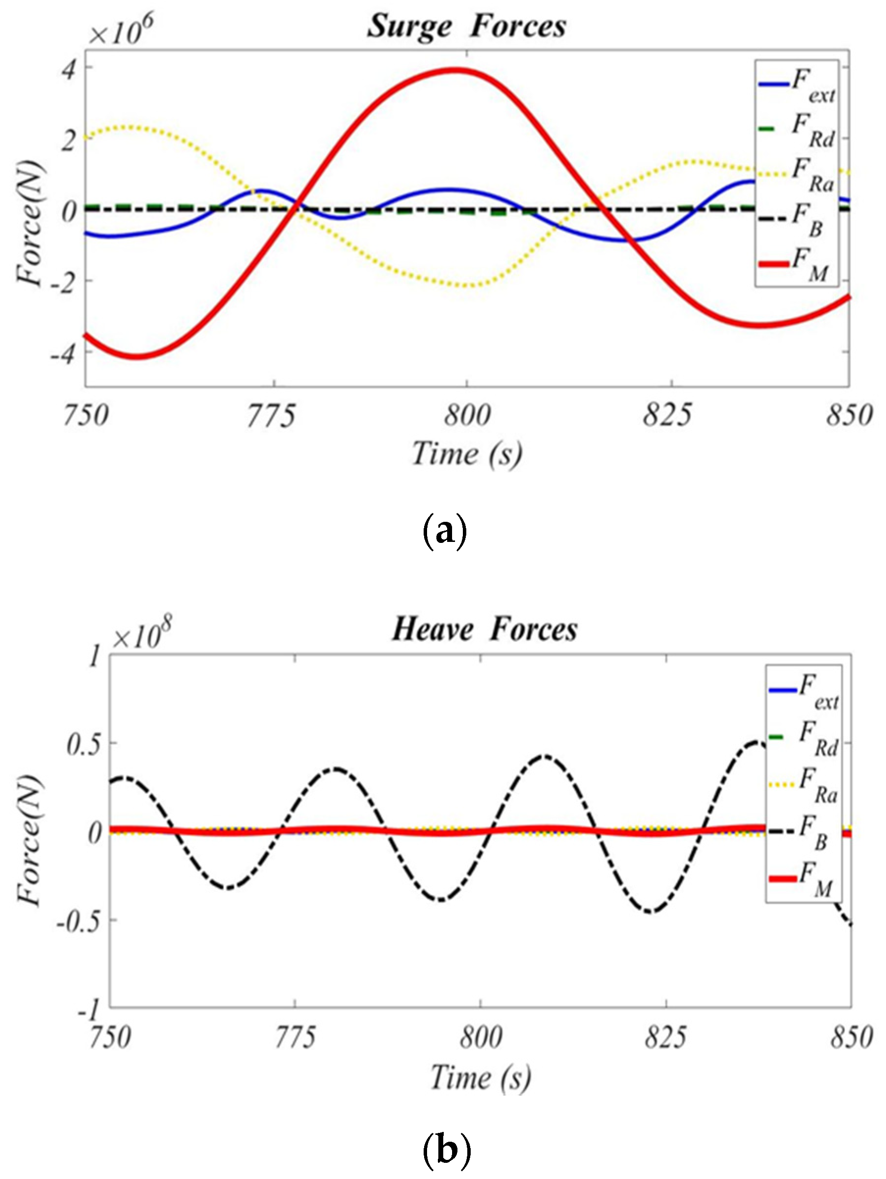
- From the computed results of UMaine-Hywind spar in irregular seas, the decrease in the water depth would lead to more prominent resonance peaks of pitch RAOs and also shift the peaks to the high-frequency region as a result of proximity to the seabed.
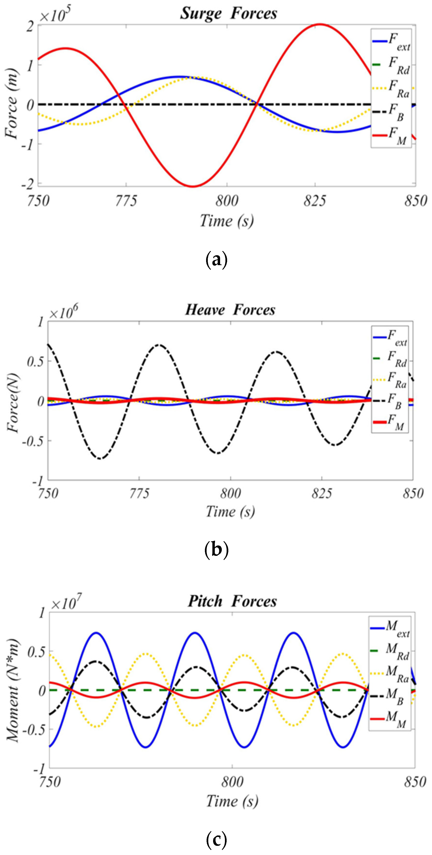
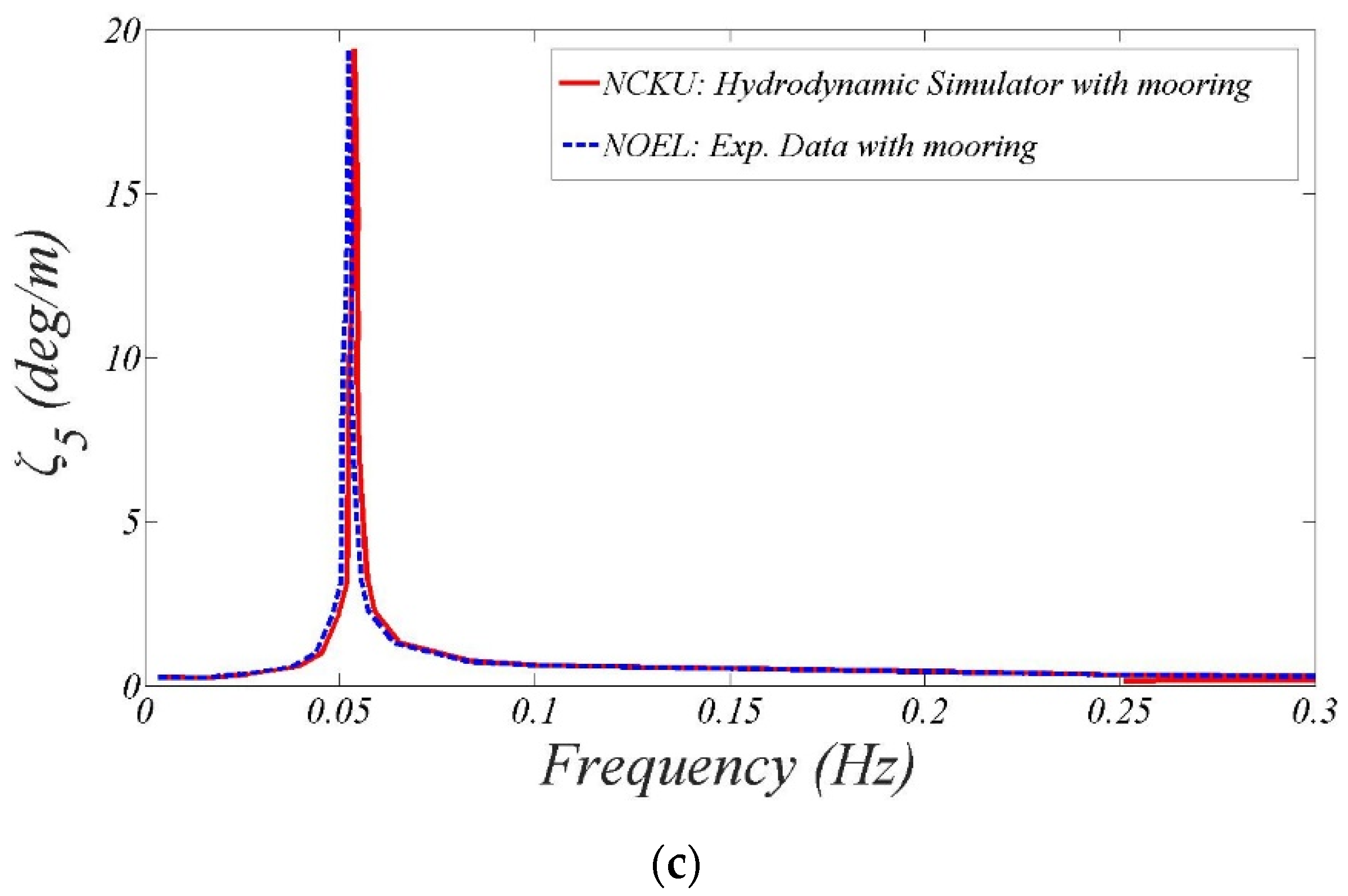
- It is demonstrated in this paper that the surge RAO is considerably larger than heave and pitch RAOs for the TLP concept due to high stiffening in the vertical plane of the taut-leg mooring system. Specifically, the large cross-sectional areas of the pontoons for the UMaine TLP would produce larger radiation added-mass force in the surge mode than in the pitch mode.
- Concerning the floater’s stability in severe sea conditions, it is much suitable to install the spar buoy in deep water area when neglecting the cost of the mooring system. For the TLP option, it is better to consider UMaine TLP rather than MIT/NREL TLP because the surge RAO can be well suppressed.
Author Contributions
Acknowledgments
Conflicts of Interest
References
- Robertson, A.N.; Jonkman, J.M. Loads analysis of several offshore floating wind turbine concepts. In Proceedings of the Twenty-First International Offshore and Polar Engineering Conference: International Society of Offshore and Polar Engineers, Maui, HI, USA, 19–24 June 2011. [Google Scholar]
- Statoil. Hywind by Statoil: The Floating Wind Turbine; Statoil: Stavanger, Norway, 2012. [Google Scholar]
- Shen, M.C.; Hu, Z.G.; Liu, G.L. Dynamic response and viscous effect analysis of a TLP-type floating wind turbine using a coupled aero-hydro-mooring dynamic code. Renew. Energy 2016, 99, 800–812. [Google Scholar] [CrossRef]
- Bachynski, E.E.; Moan, T. Design considerations for tension leg platform wind turbines. Mar. Struct. 2012, 29, 89–114. [Google Scholar] [CrossRef]
- DNV-GL. Design of floating wind turbine structures. Offshore Standard DNV-OS-J103 2013, 5, 1–124. [Google Scholar]
- Tran, T.T.; Kim, D.H. Fully coupled aero-hydrodynamic analysis of a semi-submersible FOWT using a dynamic fluid body interaction approach. Renew. Energy 2016, 92, 244–261. [Google Scholar] [CrossRef]
- Liu, Y.C.; Xiao, Q.; Incecik, A.; Peyrard, C.; Wan, D.C. Establishing a fully coupled CFD analysis tool for floating offshore wind turbines. Renew. Energy 2017, 112, 280–301. [Google Scholar] [CrossRef]
- Butterfield, S.; Musial, W.; Jonkman, J.; Sclavounos, P. Engineering Challenges for Floating Offshore Wind Turbines; National Renewable Energy Laboratory (NREL): Golden, CO, USA, 2007.
- James, R.; Ros, M.C. Floating Offshore Wind: Market and Technology Review; Carbon Trust UK: London, UK, 2015; p. 168. [Google Scholar]
- Chen, Z.-Z.; Tarp-Johansen, N.J.; Jensen, J.J. Mechanical characteristics of some deepwater floater designs for offshore wind turbines. Wind Eng. 2006, 30, 417–430. [Google Scholar] [CrossRef]
- Al-Solihat, M.K.; Nahon, M. Stiffness of slack and taut moorings. Ships Offshore Struc. 2016, 11, 890–904. [Google Scholar] [CrossRef]
- Matha, D. Model Development and Loads Analysis of an Offshore Wind Turbine on a Tension Leg Platform with a Comparison to Other Floating Turbine Concepts: April 2009; National Renewable Energy Laboratory (NREL): Golden, CO, USA, 2010.
- Karimirad, M.; Moan, T. Wave-and wind-induced dynamic response of a spar-type offshore wind turbine. J. Waterw. Port Coast. Ocean Eng. 2011, 138, 9–20. [Google Scholar] [CrossRef]
- Amo, O.M.; Fossen, T.I. Finite element modelling of moored vessels. Math Comp. Model Dyn. 2001, 7, 47–75. [Google Scholar] [CrossRef]
- Hooke, R.; Jeeves, T.A. Direct search solution of numerical and statistical problems. J. Assoc. Comput. Mach. 1961, 8, 212–229. [Google Scholar] [CrossRef]
- Korvin-Kroukovsky, B.V.; Jacobs, W.R. Pitching and Heaving Motions of a Ship in Regular Waves; Stevens Institute of Technology: Hoboken, NJ, USA, 1957. [Google Scholar]
- Fang, M.-C.; Chen, T.-Y. A parametric study of wave loads on trimaran ships traveling in waves. Ocean Eng. 2008, 35, 749–762. [Google Scholar] [CrossRef]
- Lin, Y.-H.; Hsu, C.-L.; Kao, S.-H. Hydrodynamics of the wind float OC3-Hywind with mooring loads estimated by the modular system. J. Mar. Sci. Technol. 2018, 1–12. [Google Scholar] [CrossRef]
- Hess, J.L.; Smith, A. Calculation of Non-Lifting Potential Flow about Arbitrary Three-Dimensional Bodies; Douglas Aircraft Co: Long Beach, CA, USA, 1962. [Google Scholar]
- Shen, H.-T.; Farell, C. Numerical calculation of the wave integrals in the linearized theory of water waves. J. Ship Res. 1975, 21, 1–10. [Google Scholar]
- Telste, J.; Noblesse, F. Numerical evaluation of the Green function of water-wave radiation and diffraction. J. Ship Res. 1986, 30, 69–84. [Google Scholar]
- Salvesen, N.; Tuck, E.; Faltinsen, O. Ship motions and sea loads. Trans. SNAME 1970, 78, 250–287. [Google Scholar]
- ETAP_Balkan. Wind Turbine Modeling; ETAP_Balkan: Istanbul, Turkey, 2018. [Google Scholar]
- Andersen, M.T.; Hindhede, D.; Lauridsen, J. Influence of model simplifications excitation force in surge for a floating foundation for offshore wind turbines. Energies 2015, 8, 3212–3224. [Google Scholar] [CrossRef]
- Jonkman, J.M.; Sclavounos, P.D. Development of Fully Coupled Aeroelastic and Hydrodynamic Models for Offshore Wind Turbines; Technical Report No NREL/CP-500-39066; National Renewable Energy Laboratory: Golden, CO, USA, 2006.
- Jonkman, J.; Butterfield, S.; Musial, W.; Scott, G. Definition of a 5-MW Reference Wind Turbine for Offshore System Development; Technical Report No NREL/TP-500-38060; National Renewable Energy Laboratory: Golden, CO, USA, 2009.
- Fang, M.-C.; Chen, R.-Y. Three-dimensional solution of the diffraction force on a ship in wave. In Proceedings of the Eighth International Offshore and Polar Engineering Conference: International Society of Offshore and Polar Engineers, Montreal, QC, Canada, 24–29 May 1998. [Google Scholar]
- Cummins, W. The Impulse Response Function and Ship Motions; David Taylor Model Basin: Washington, DC, USA, 1962. [Google Scholar]
- Hasselmann, K.; Barnett, T.; Bouws, E.; Carlson, H.; Cartwright, D.; Enke, K.; Ewing, J.A.; Gienapp, H.; Hasselmann, D.E.; Kruseman, P.; et al. Measurements of wind-wave growth and swell decay during the Joint North Sea Wave Project (JONSWAP). Ergänzungsheft 1973, 8–12. [Google Scholar]
- Ramachandran, G.; Robertson, A.; Jonkman, J.; Masciola, M. Investigation of response amplitude operators for floating offshore wind turbines. In Proceedings of the Twenty-third International Offshore and Polar Engineering Conference: International Society of Offshore and Polar Engineers, Alaska, AK, USA, 30 June–5 July 2013. [Google Scholar]
- Lee, C.-H. WAMIT Theory Manual; Massachusetts Institute of Technology: Cambridge, MA, USA, 1995. [Google Scholar]
- Ruzzo, C.; Fiamma, V.; Collu, M.; Failla, G.; Nava, V.; Arena, F. On intermediate-scale open-sea experiments on floating offshore structures: Feasibility and application on a spar support for offshore wind turbines. Mar. Struct. 2018, 61, 220–237. [Google Scholar] [CrossRef]
- Ruzzo, C.; Fiamma, V.; Nava, V.; Collu, M.; Failla, G.; Arena, F. Progress on the experimental set-up for the testing of a floating offshore wind turbine scaled model in a field site. Wind Eng. 2016, 40, 455–467. [Google Scholar] [CrossRef]
- Belibassakis, K. A boundary element method for the hydrodynamic analysis of floating bodies in variable bathymetry regions. Eng. Anal. Bound Elem. 2008, 32, 796–810. [Google Scholar] [CrossRef]
- Shim, S.; Kim, M. Rotor-floater-tether coupled dynamic analysis of offshore floating wind turbines. In Proceedings of the Eighteenth International Offshore and Polar Engineering Conference: International Society of Offshore and Polar Engineers, Vancouver, BC, Canada, 6–11 July 2008. [Google Scholar]
- Tracy, C.C.H. Parametric Design of Floating Wind Turbines; Massachusetts Institute of Technology: Cambridge, MA, USA, 2007. [Google Scholar]


| OC3-Hywind Spar | UMaine-Hywind Spar | MIT/NREL TLP | UMaine TLP | |
|---|---|---|---|---|
| Water Depth (m) | 320 | 200 | 200 | 200 |
| Diameter (m) | 6.5–9.4 | 6.5–9.4 | 18 | 6.5 (upper column)/15 (lower column) |
| Draft (m) | 120 | 120 | 47.89 | 24 |
| Mass, including ballast (kg) | 7.466×10⁶ | 7.466 × 10⁶ | 8.6 × 10⁶ | 7.7494 × 10⁵ |
| CM location of the platform below SWL (m) | 89.92 | 89.92 | 40.61 | 19.72 |
| Roll inertia about CM ( kg·m2) | 4.229 × 10⁹ | 4.229 × 10⁹ | 5.716 × 10⁸ | 1.5078 × 10⁸ |
| Pitch inertia about CM ( kg·m2) | 4.229 × 10⁹ | 4.229 × 10⁹ | 5.716 × 10⁸ | 1.5078 × 10⁸ |
| Yaw inertia about CM ( kg·m2) | 1.642 × 10⁸ | 1.642 × 10⁸ | 3.614 × 10⁸ | 9.885 × 10⁷ |
| Mooring System | Catenary | Catenary | Taut-Leg | Taut-Leg |
| Number of mooring lines | 3 | 3 | 8 (4 pairs) | 3 |
| Un-stretched line length (m) | 902.2 | 468 | 151.7 | 171.4 |
| Line diameter (m) | 0.09 | 0.09 | 0.127 | 0.222 |
| Line mass density (kg/m) | 77.71 | 145 | 116 | 302.89 |
| Line extensional stiffness (N) | 3.842 × 10⁸ | 3.842 × 10⁸ | 1,500,000,000 | 7,720,000,000 |
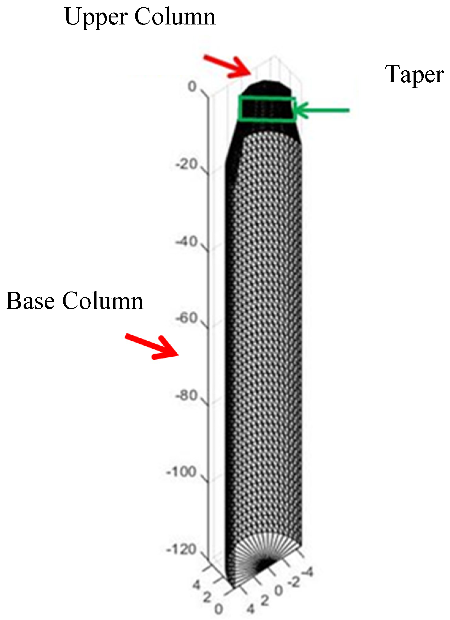
| Length/Width (m/m) | Panel Type | Panel Number | |
|---|---|---|---|
| Upper Column | 1.63/0.33 | Triangular | 642 |
| Taper | 0.86/0.5 | Triangular | 236 |
| Lower Column | 1.72/1 | Triangular | 442 |
| Length/Width (m/m) | Panel Type | Number of Panels | |
|---|---|---|---|
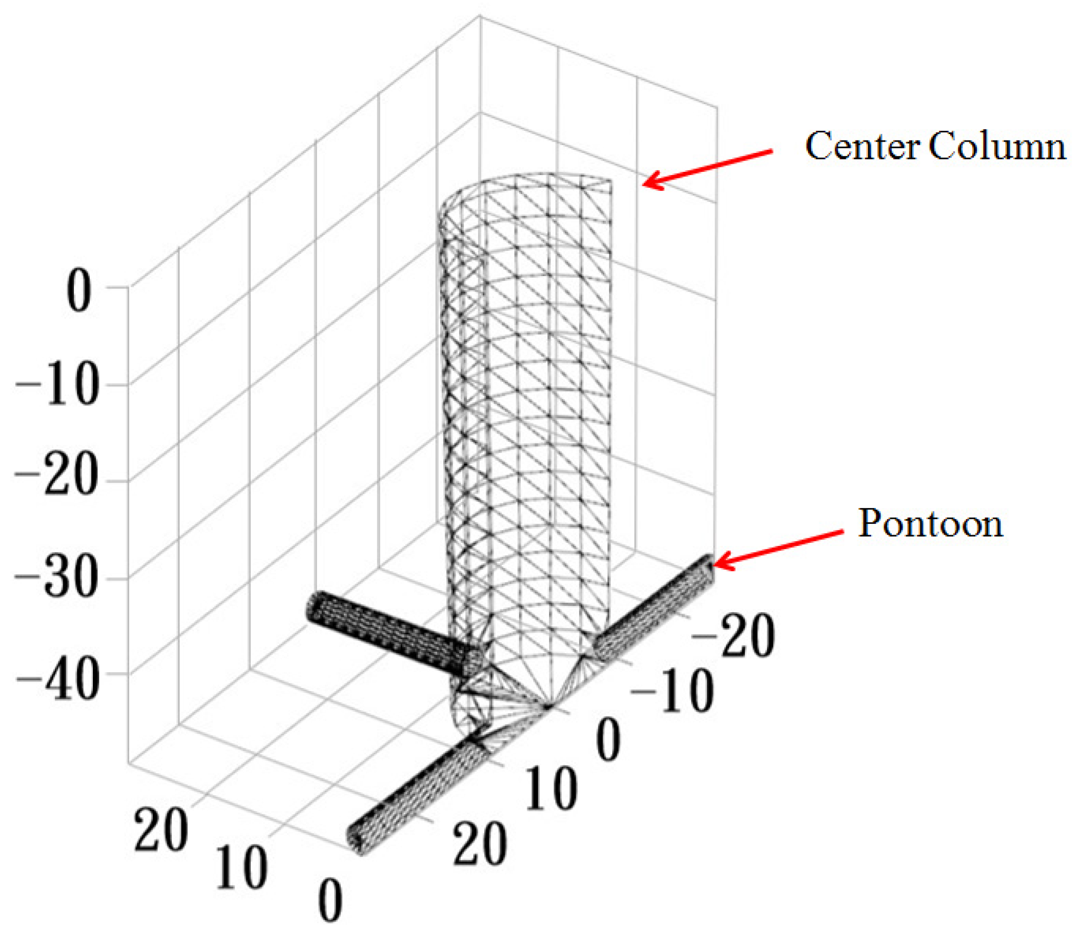
| Center Column | 2.92/2.81 | Triangular | 1163 |
| Pontoon | 2/0.54 | Triangular | 843 |
| Length/Width (m/m) | Panel Type | Panel Number | |
|---|---|---|---|
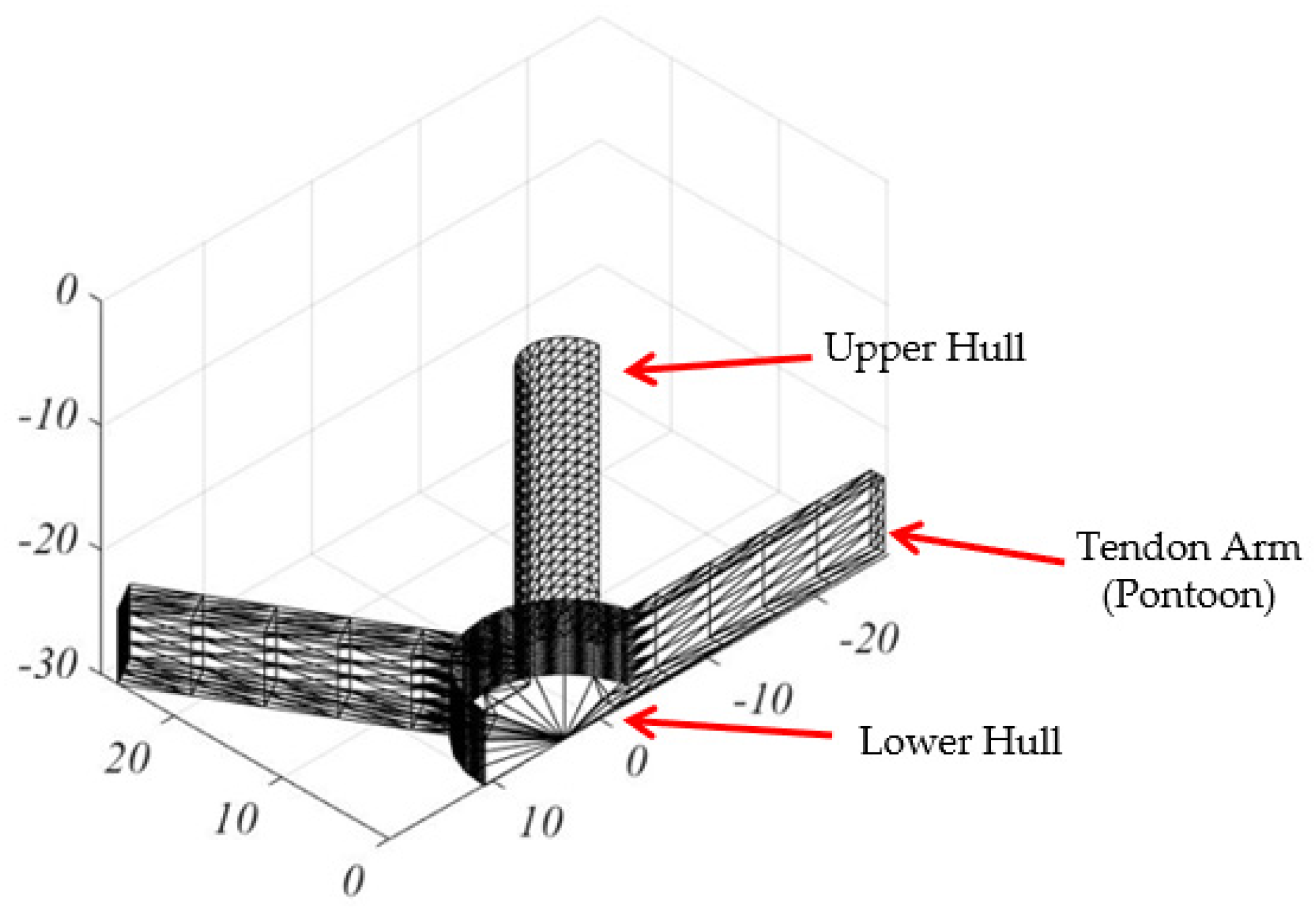
| Upper Hull | 0.79/1 | Triangular | 648 |
| Lower Hull | 2/0.25 | Triangular | 332 |
| Tendon Arm (Pontoon) | 5/0.6 | Triangular | 340 |
© 2019 by the authors. Licensee MDPI, Basel, Switzerland. This article is an open access article distributed under the terms and conditions of the Creative Commons Attribution (CC BY) license (http://creativecommons.org/licenses/by/4.0/).
Share and Cite
Lin, Y.-H.; Kao, S.-H.; Yang, C.-H. Investigation of Hydrodynamic Forces for Floating Offshore Wind Turbines on Spar Buoys and Tension Leg Platforms with the Mooring Systems in Waves. Appl. Sci. 2019, 9, 608. https://doi.org/10.3390/app9030608
Lin Y-H, Kao S-H, Yang C-H. Investigation of Hydrodynamic Forces for Floating Offshore Wind Turbines on Spar Buoys and Tension Leg Platforms with the Mooring Systems in Waves. Applied Sciences. 2019; 9(3):608. https://doi.org/10.3390/app9030608
Chicago/Turabian StyleLin, Yu-Hsien, Shin-Hung Kao, and Cheng-Hao Yang. 2019. "Investigation of Hydrodynamic Forces for Floating Offshore Wind Turbines on Spar Buoys and Tension Leg Platforms with the Mooring Systems in Waves" Applied Sciences 9, no. 3: 608. https://doi.org/10.3390/app9030608
APA StyleLin, Y.-H., Kao, S.-H., & Yang, C.-H. (2019). Investigation of Hydrodynamic Forces for Floating Offshore Wind Turbines on Spar Buoys and Tension Leg Platforms with the Mooring Systems in Waves. Applied Sciences, 9(3), 608. https://doi.org/10.3390/app9030608