Miniaturized Optical Encoder with Micro Structured Encoder Disc

 ,
,
Abstract
:1. Introduction
2. A New Approach for Optical Encoders
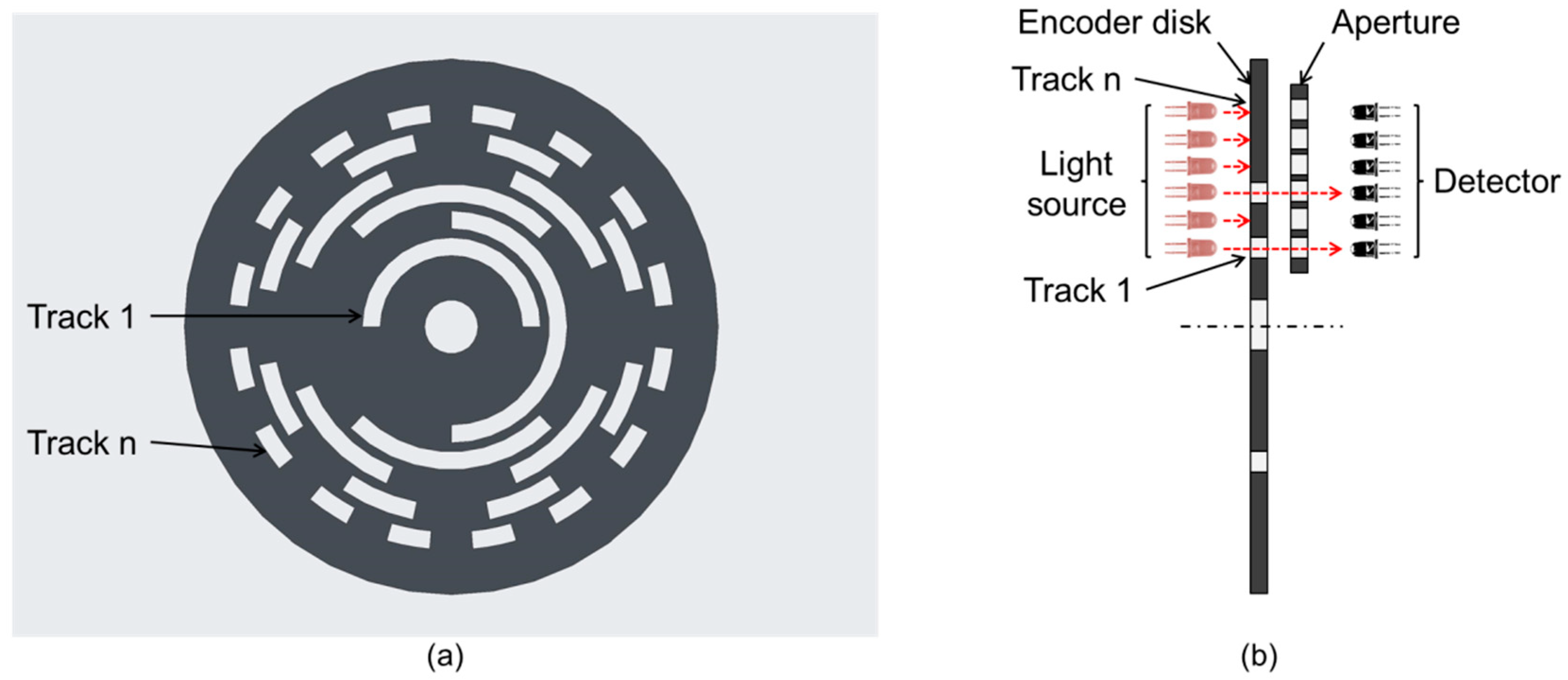
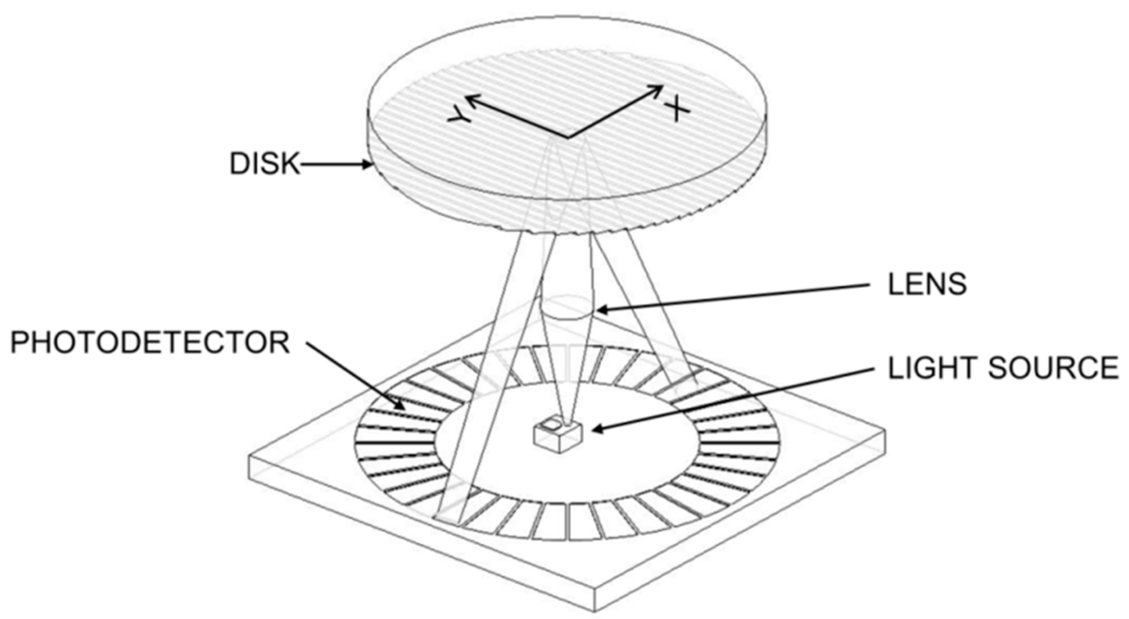
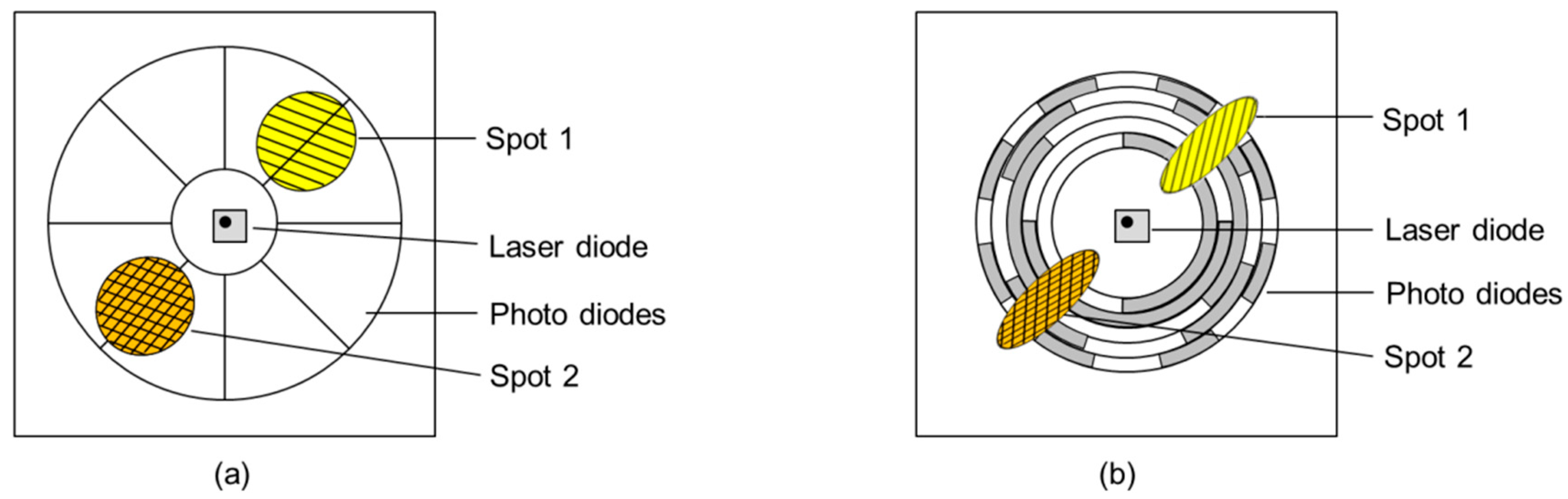
2.1. Main Principle of the Encoder
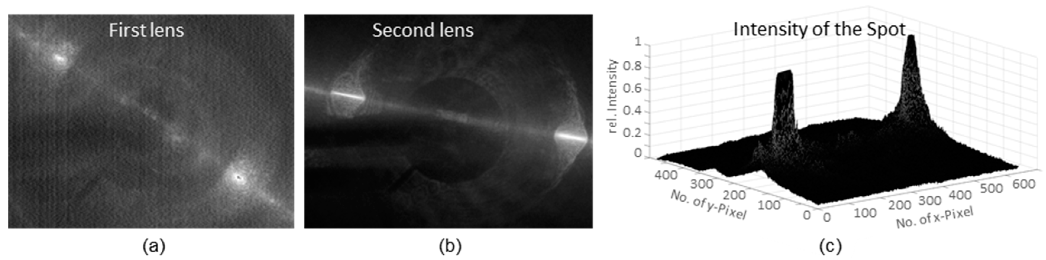
2.2. Proof of Principle
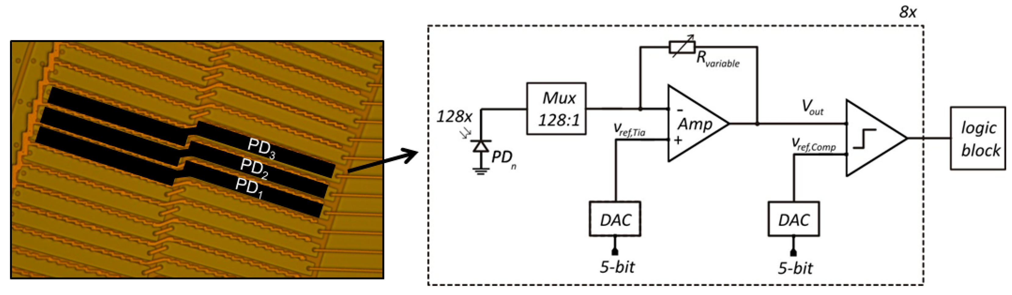
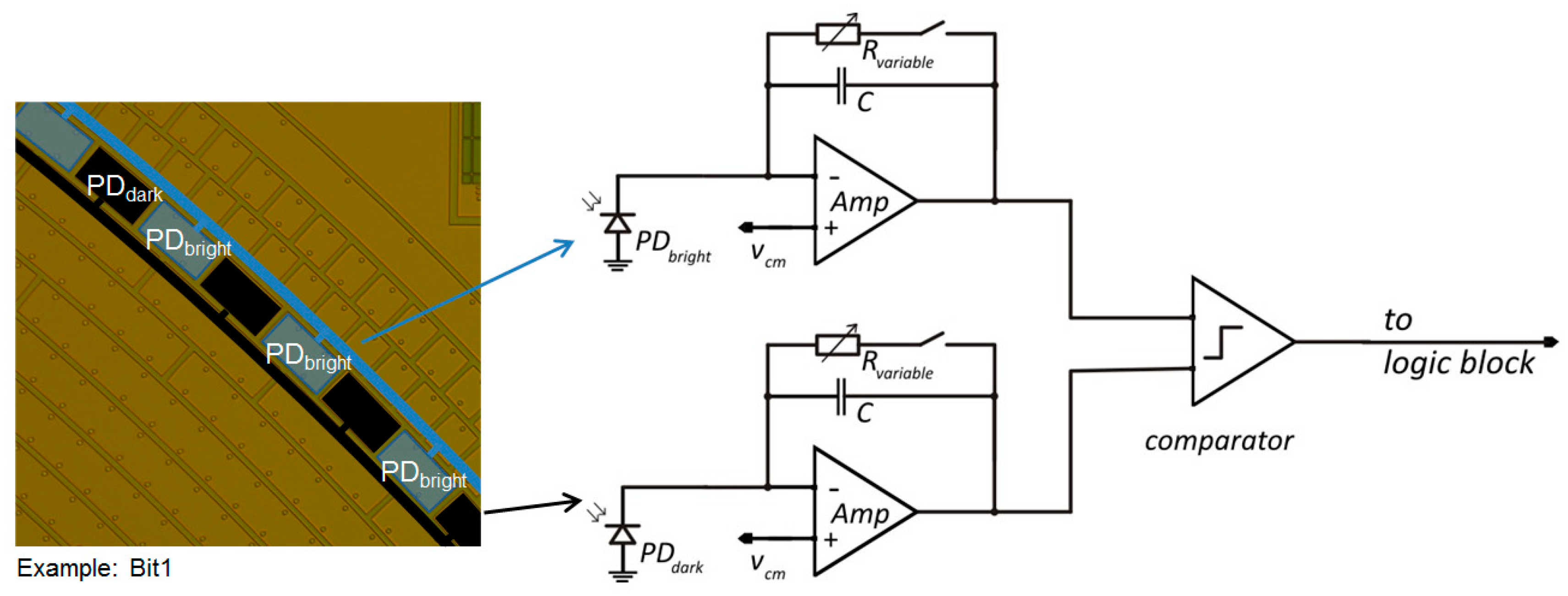
2.3. Photodiode Readout Circuits of the Opto-ASIC
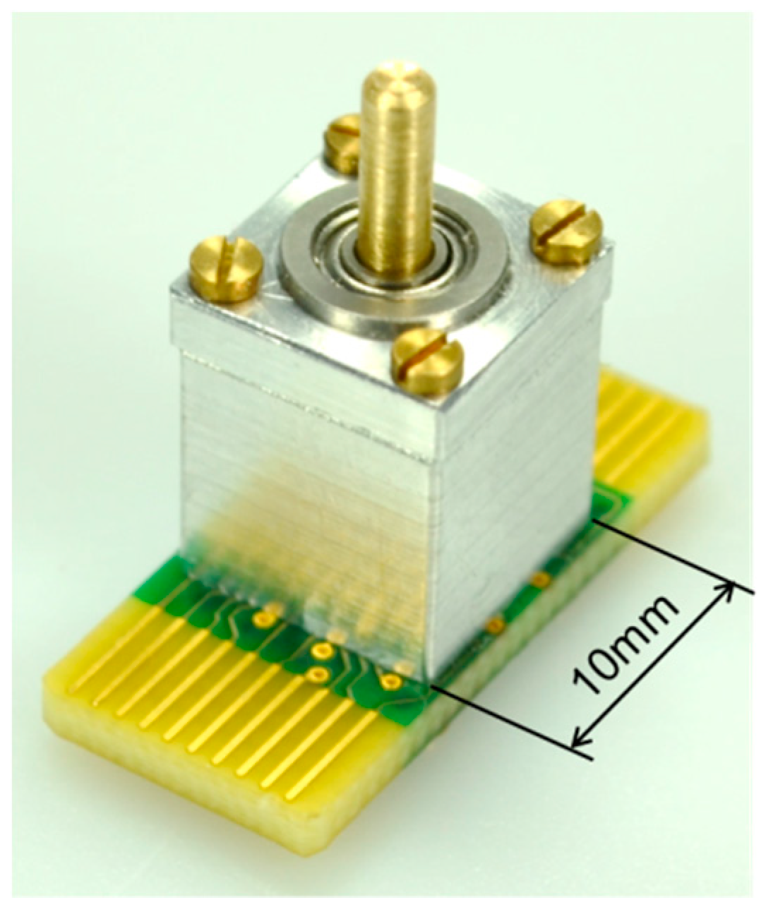
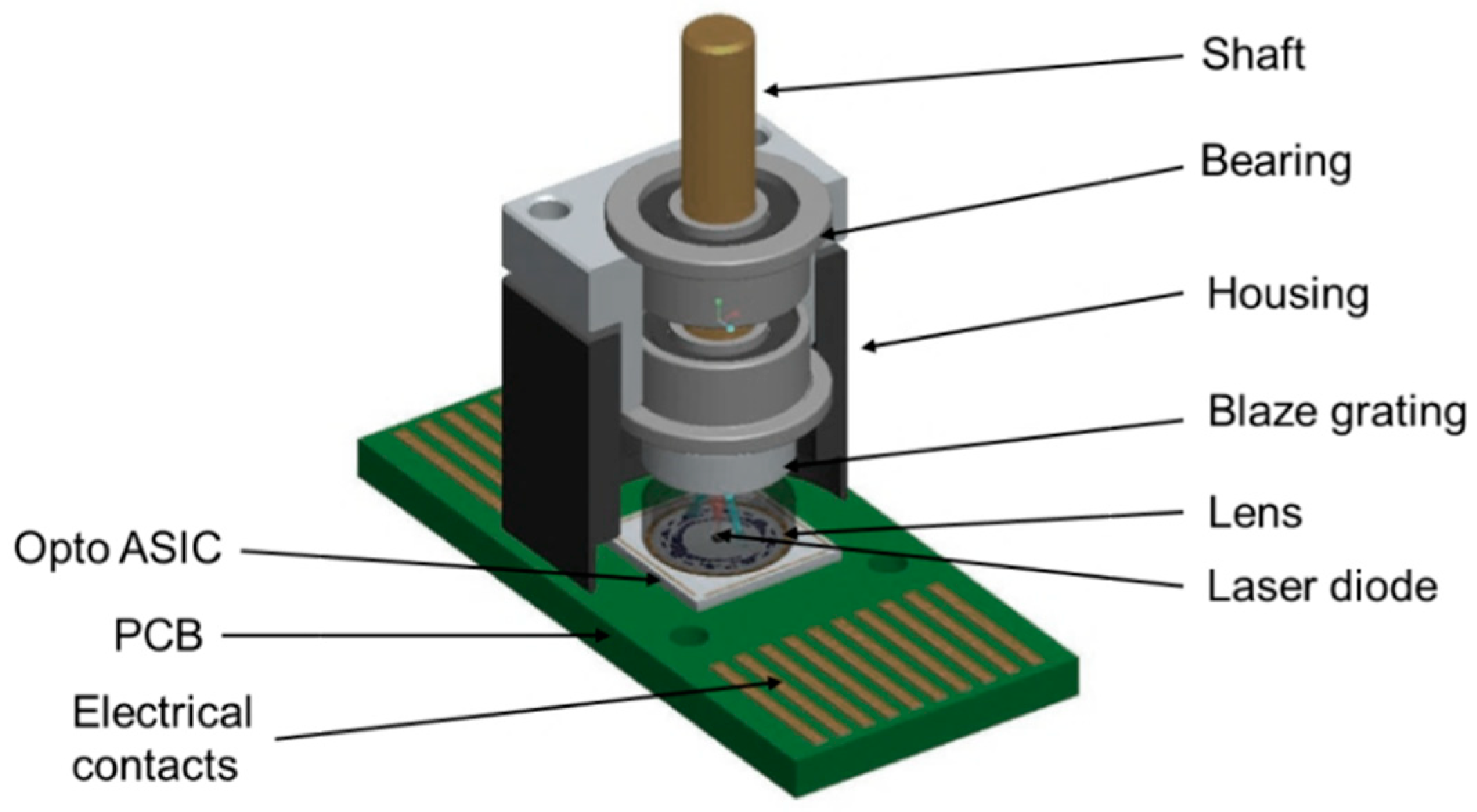
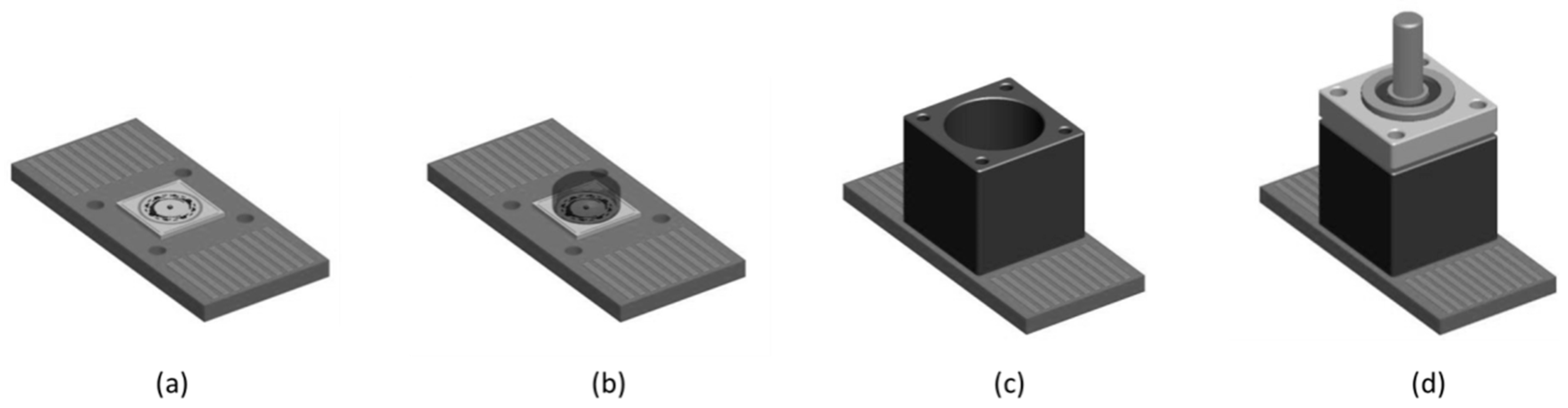
2.4. Design Concept of the Demonstrator for the Miniaturized Optical Encoder
3. Results
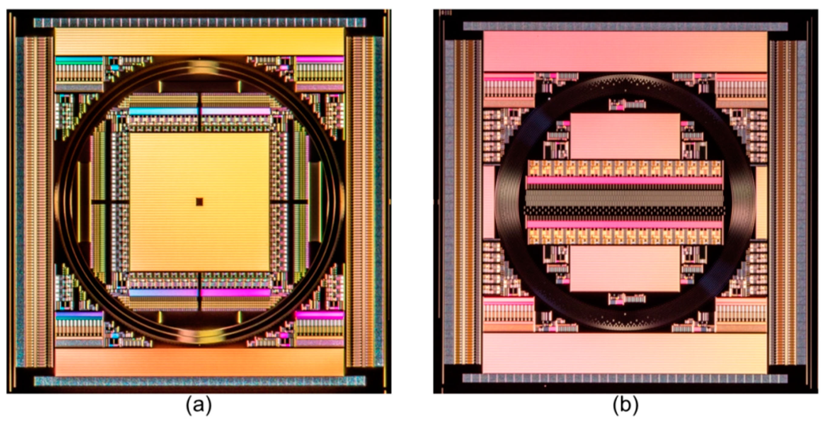
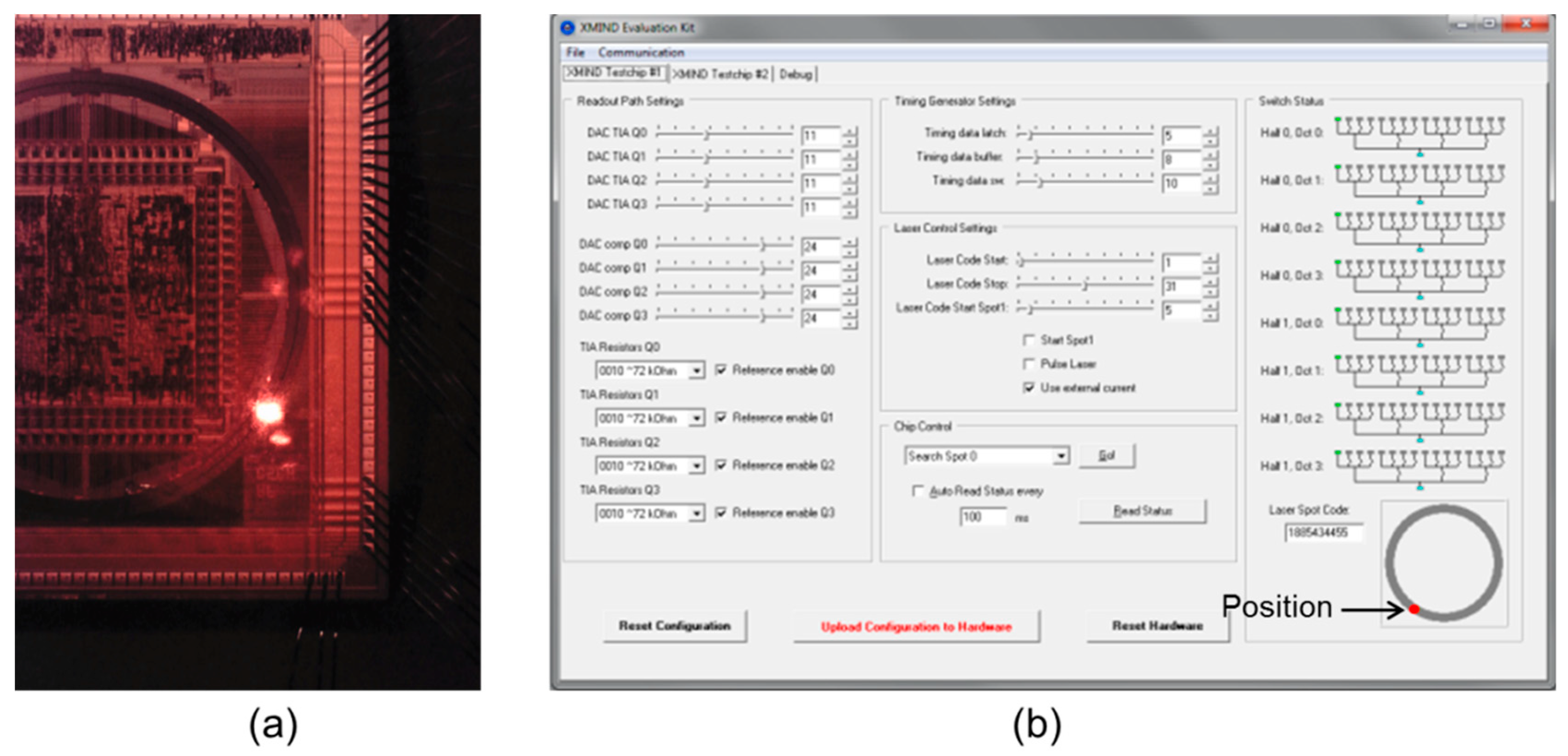
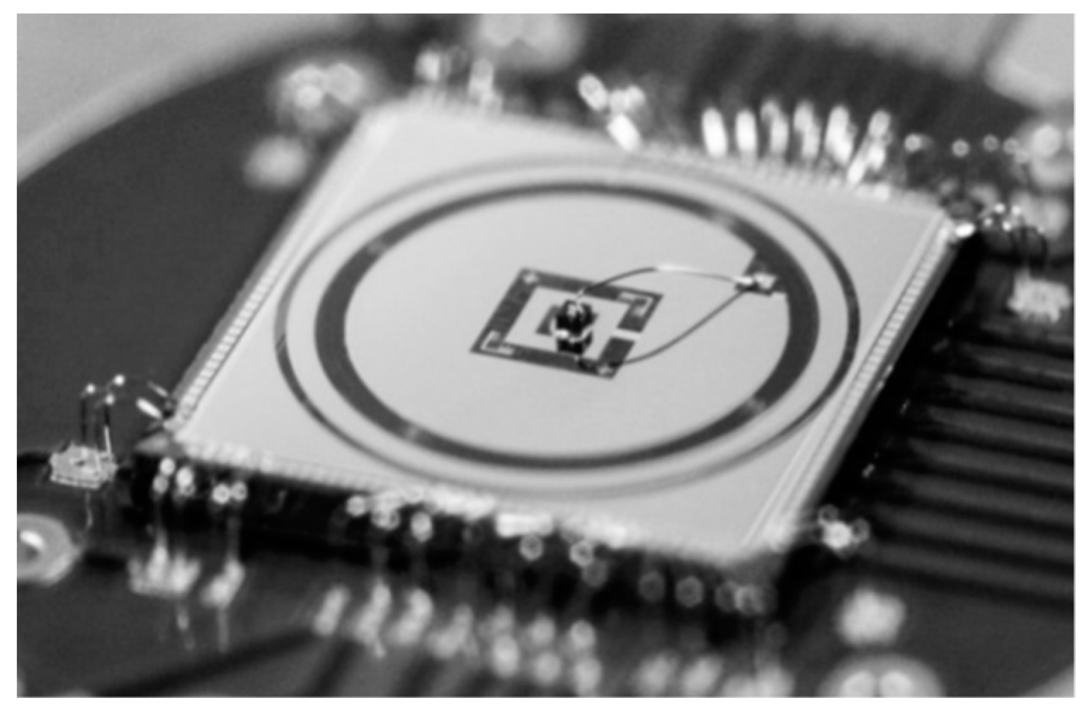
3.1. Opto-ASIC
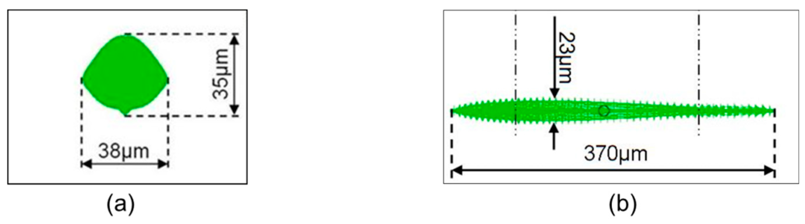
3.2. Light Source
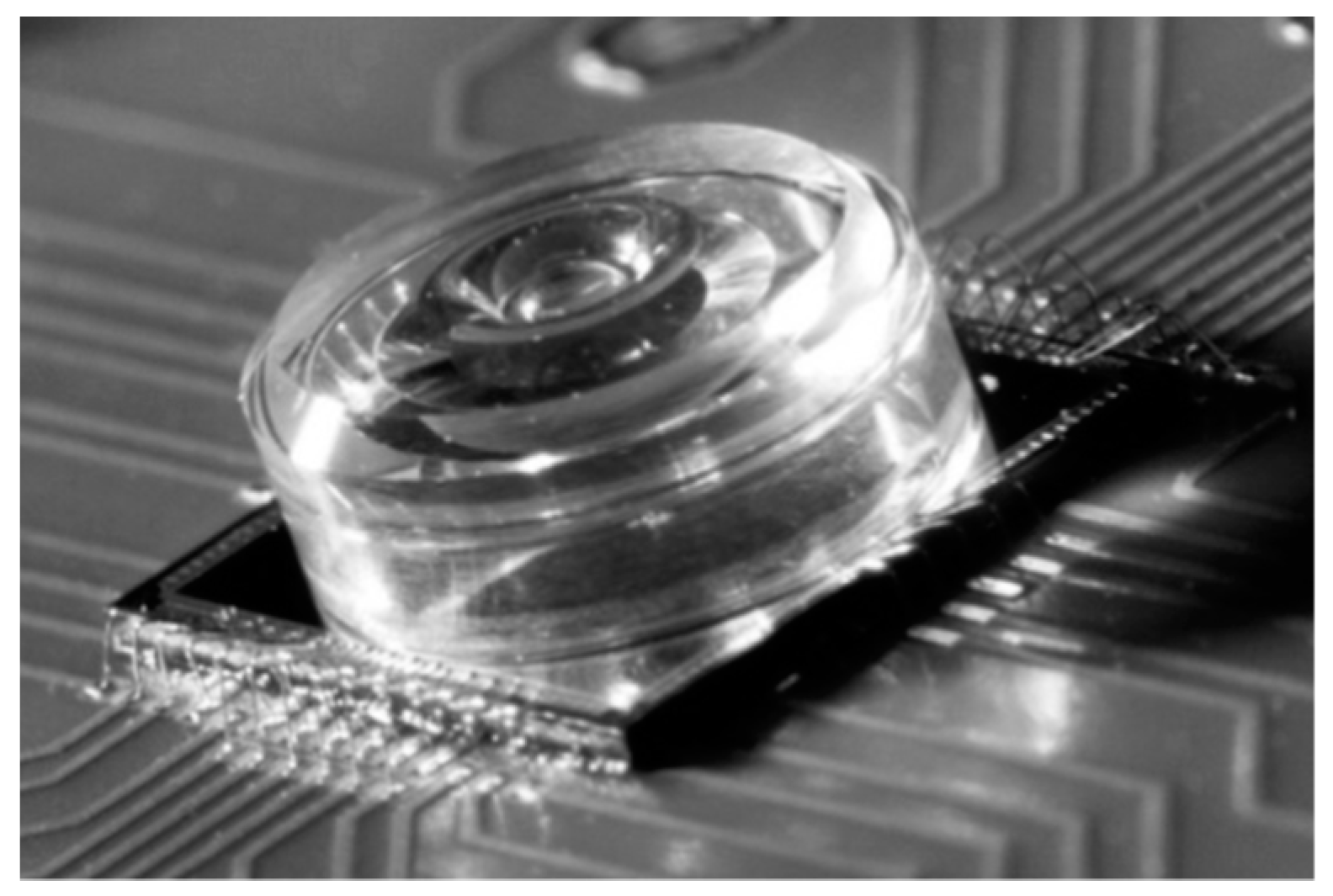
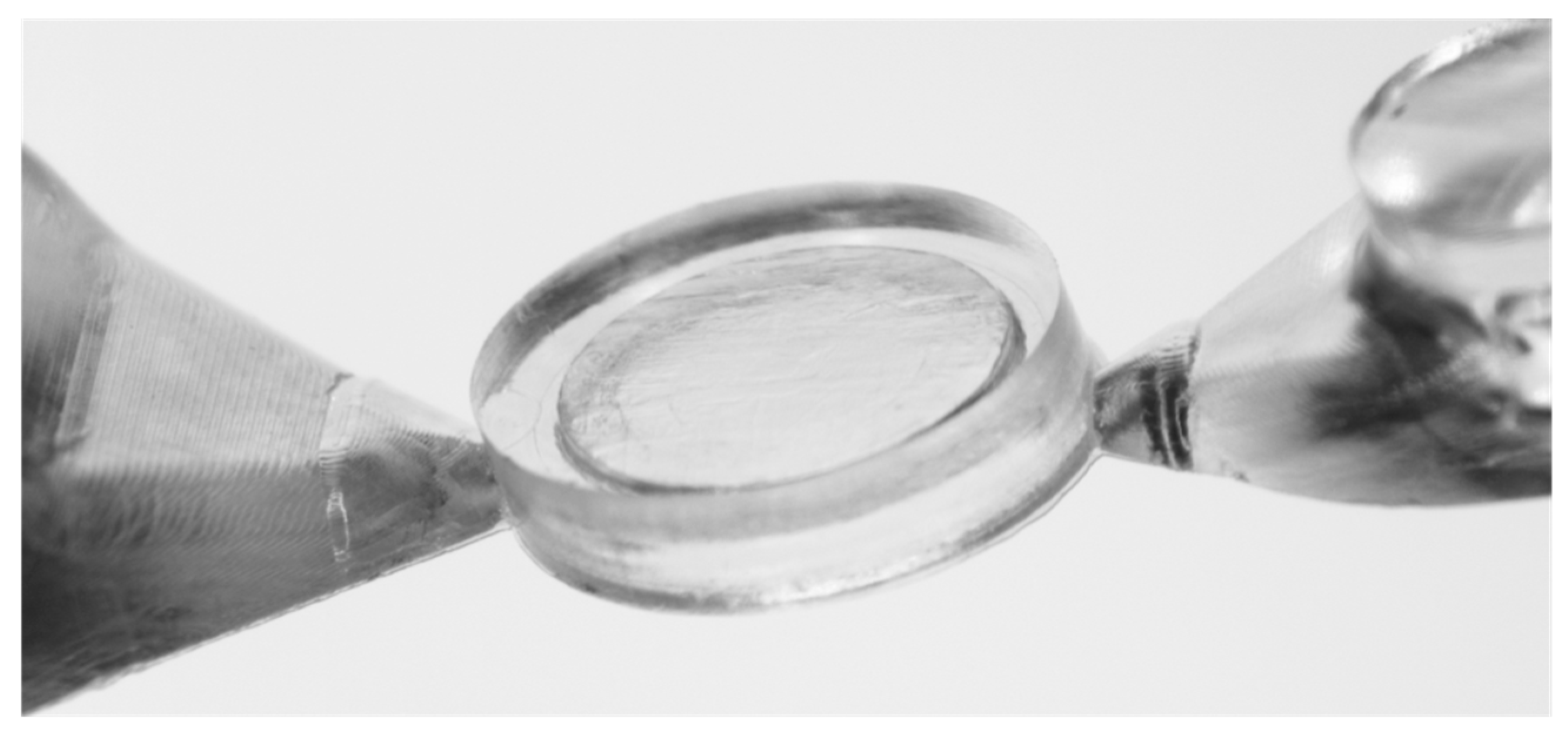
3.3. Micro Lens
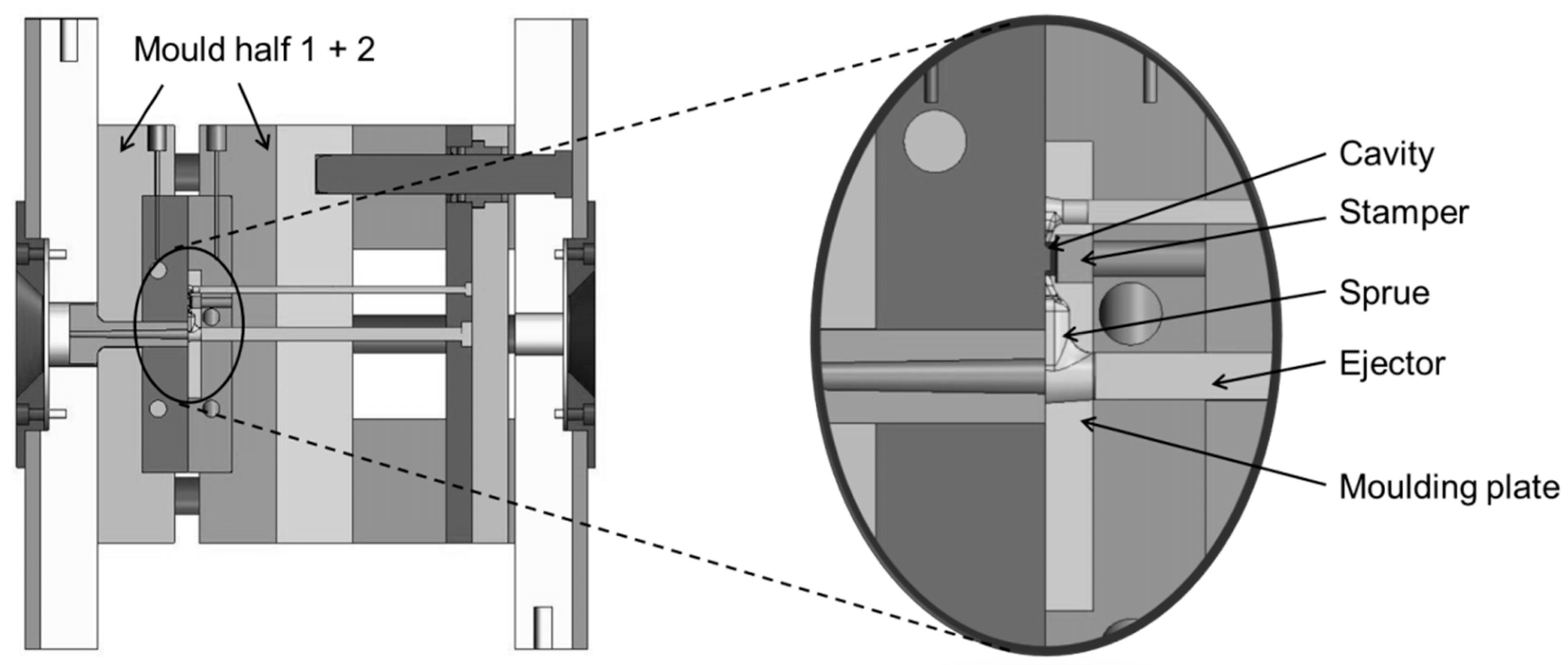
3.4. Manufacturing of the Micro Structured Encoder Discs
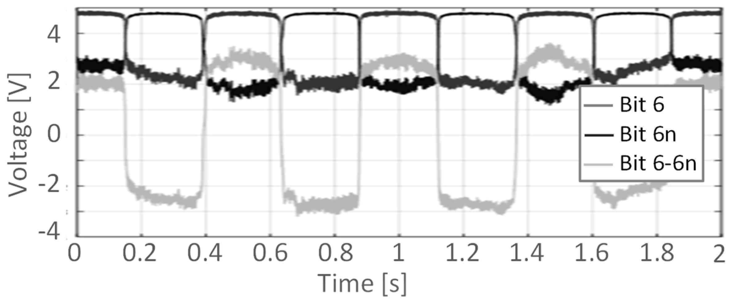
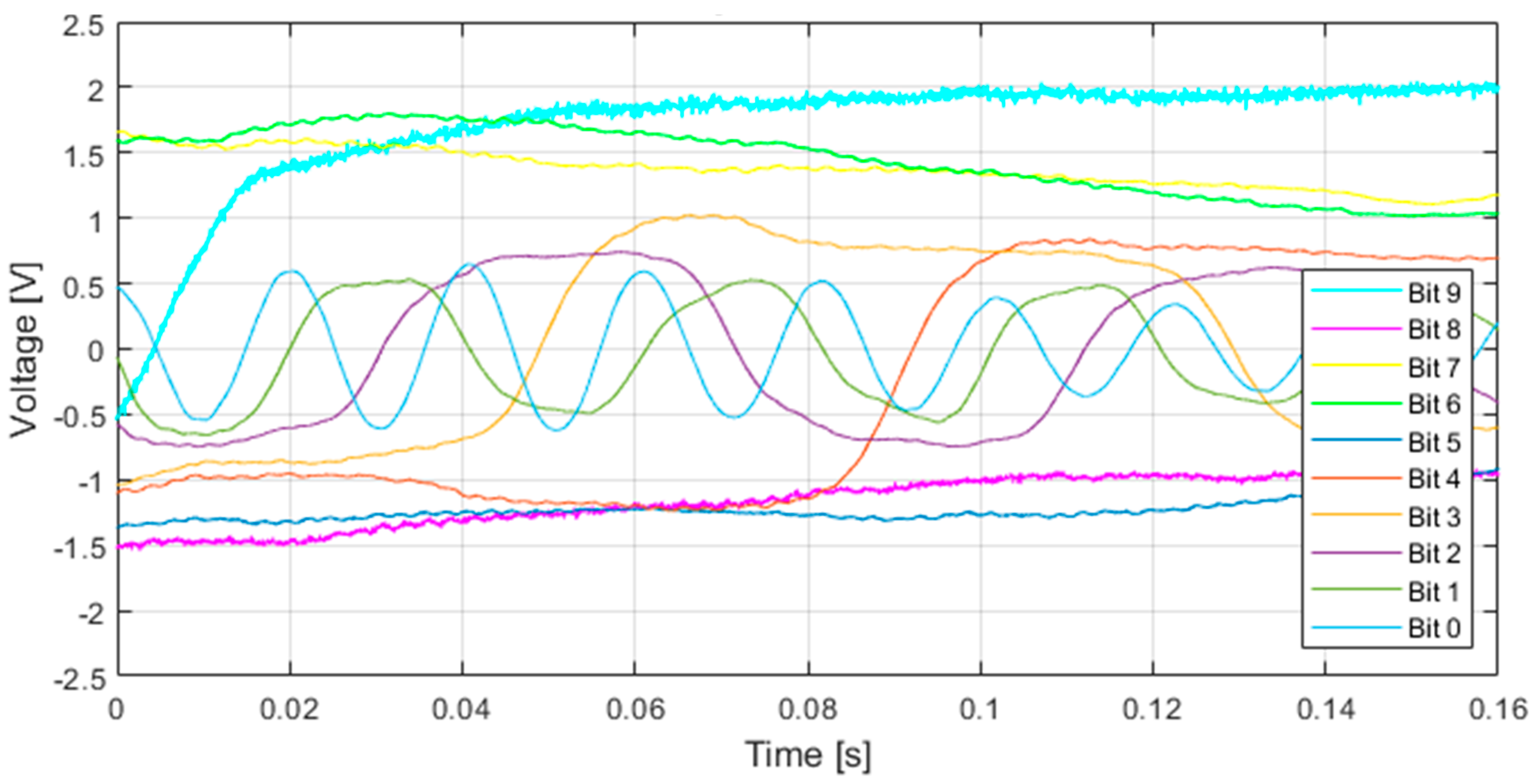
4. Characterization of the Miniaturized Encoder
5. Discussion
6. Conclusions and Outlook
Author Contributions
Funding
Conflicts of Interest
References
- Eitel, E. Basics of Rotary Encoders: Overview and New Technologies. Machine Design, 2014. Available online: www.machinedesign.com (accessed on 10 January 2019).
- Market Research Report. Global Industrial Encoder Market 2017–2021. 2017. Available online: www.technavio.com (accessed on 10 January 2019).
- Global Rotary Encoder Market Research Report 2017. 2018. Available online: www.marketresearchstore.com (accessed on 10 January 2019).
- Incremental Optical Encoder. Contactless Position Sensors General Information, Presentation. 2016. Available online: www.exxelia.com/uploads/PDF/ie09-v1.pdf (accessed on 7 January 2019).
- Monari, G. Understanding Resolution In Optical And Magnetic Encoders. 2013. Available online: www.electronicdesign.com (accessed on 7 January 2019).
- Seybold, J. Untersuchungen zur Industrialisierung von Miniaturisierten Optischen Drehwinkelsensoren mit Diffraktiver Kodierscheibe aus Kunststoff; Dissertation Universität Stuttgart; Verlag Dr. Hut: München, Germany, 2013. [Google Scholar]
- CUI Inc. Absolute, Optical Shaft Encoder. Datasheet of the Series MAS10-256G. 2018. Available online: www.cui.com (accessed on 26 October 2018).
- Trupke, T. Optoelektronische Miniatur-Drehgeber, Einsätze in der minimalinvasiven Chirurgie. In Medizin&Technik; Konradin Verlag R. Kohlhammer GmbH: Leinfelden-Echterdingen, Germany, 2012. [Google Scholar]
- Qin, S.; Huang, Z.; Wang, X. Optical Angular Encoder Installation Error Measurement and Calibration by Ring Laser Gyroscope. IEEE Trans. Instrum. Meas. 2010, 59, 506–511. [Google Scholar] [CrossRef]
- Mayer, V. Untersuchungen zu Optischen Drehgebern mit Mikrostrukturierten Maßverkörperungen aus Kunststoff; Dissertation Universität Stuttgart; Verlag Dr. Hut: München, Germany, 2009. [Google Scholar]
- Hopp, D. Inkrementale und Absolute Kodierung von Positionssignalen Diffraktiver Optischer Drehgeber. Ph.D. Thesis, Universität Stuttgart, Stuttgart, Germany, 2012. [Google Scholar]
- Wibbing, D.; Binder, J.; Schinköthe, W.; Pauly, Ch.; Gachot, C.; Mücklich, F. Optical Absolute Position-Encoder by Single-Track, q-ary Pseudo-Random-Sequences for Miniature Linear Motors. In Proceedings of the Sensor + Test Conference—OPTO, Nürnberg, Germany, 7–9 June 2011. [Google Scholar]
- Hopp, D.; Pruss, C.; Osten, W.; Seybold, J.; Mayer, V.; Kück, H. Optischer inkrementaler Drehgeber in Low-Cost-Bauweise. Tm Technisches Messen 2010, 77, 358–363. [Google Scholar] [CrossRef]
- Mayer, V. A new concept for an absolutely encoded angular resolver. In Proceedings of the 4M 2007 Conference on Multi-Material Micro Manufacture, Borovets, Bulgaria, 3–5 October 2007. [Google Scholar]
- Seybold, J.; Mayer, V.; Kück, H.; Hopp, D.; Pruss, Ch.; Osten, W. Hochauflösender optischer Drehgeber mit MID-Optikmodul. In Proceedings of the 6th Paderborner Workshop, Entwurf mechatronischer Systeme, Paderborn, Germany, 2–3 April 2009. [Google Scholar]
- Seybold, J.; Fritz, K.-P.; Mayer, V.; Kück, H. Miniature Optical Encoder for Reflow Solder Mounting. In Proceedings of the 8th International Conference on Multi-Material Micro Manufacture, Stuttgart, Germany, 8–10 November 2011. [Google Scholar]
- Seybold, J.; Scherjon, C. Untersuchungen zu extrem miniaturisierten optischen Drehgebern (X-MIND). IGF-Vorhaben 17898 N, Abschlussbericht. Available online: www.hahn-schickard.de (accessed on 20 December 2016).
- Edmund Optics, Ruled Holo Grating 600x800n. Available online: www.edmundoptics.de (accessed on 18 July 2015).
- Craubner, S.; Graf, H.-G.; Harendt, C.; Platz, W.; Schubert, M. Hochleistungs-Front-End-Elektronik. Endbericht Phase 2, Entwicklung “Integrierter Detektorsysteme”; BMBF FKZ 50TT9724; BMBF: Bonn, Germany, 2002. [Google Scholar]
- Bülau, A.; Seybold, J.; Fritz, K.-P.; Frank, A.; Scherjon, C.; Burghartz, J.; Zimmermann, A. Miniaturized optical encoder with micro structured encoder disk. In Proceedings of the WCMNM-Conference, World Congress on Micro and Nano Manufacturing, Portorož, Slovenia, 18–20 September 2018. [Google Scholar]
- Höhn, M. Sensorgeführte Montage Hybrider Mikrosysteme; Herbert Utz Verlag: München, Germany, 2001. [Google Scholar]
- Martin, C. Commissioning and Optimization of a Pick-up Tool with Integrated Beam Profiling for Precise Assembling of Lenses; Student Research Project; University of Stuttgart: Stuttgart, Germany, 2015. [Google Scholar]
- High-Precision Sine/Cosine Interpolation. White Paper. 2014. Available online: www.ichaus.de (accessed on 17 September 2018).


| Feature/Series | CUI MAS10 | CUI MES6 |
|---|---|---|
| Method | Absolute | Incremental |
| Resolution | 256 positions | 500 positions |
| Speed | 6000 rpm | 6000 rpm |
| Interface | Digital | Digital |
| Temperature | 0…+60 °C | 0…+60 °C |
| Size | Ø 13 mm × 16 mm | Ø 8 mm × 11 mm |
| Feature | |
|---|---|
| Method | Incremental and absolute |
| Resolution | 1024 positions |
| Speed | 12,000 rpm |
| Interface | Digital and SPI |
| Temperature | −40 … +85 °C |
| Size | 10 × 10 × 10 mm3 |
© 2019 by the authors. Licensee MDPI, Basel, Switzerland. This article is an open access article distributed under the terms and conditions of the Creative Commons Attribution (CC BY) license (http://creativecommons.org/licenses/by/4.0/).
Share and Cite
Seybold, J.; Bülau, A.; Fritz, K.-P.; Frank, A.; Scherjon, C.; Burghartz, J.; Zimmermann, A. Miniaturized Optical Encoder with Micro Structured Encoder Disc. Appl. Sci. 2019, 9, 452. https://doi.org/10.3390/app9030452
Seybold J, Bülau A, Fritz K-P, Frank A, Scherjon C, Burghartz J, Zimmermann A. Miniaturized Optical Encoder with Micro Structured Encoder Disc. Applied Sciences. 2019; 9(3):452. https://doi.org/10.3390/app9030452
Chicago/Turabian StyleSeybold, Jonathan, André Bülau, Karl-Peter Fritz, Alexander Frank, Cor Scherjon, Joachim Burghartz, and André Zimmermann. 2019. "Miniaturized Optical Encoder with Micro Structured Encoder Disc" Applied Sciences 9, no. 3: 452. https://doi.org/10.3390/app9030452
APA StyleSeybold, J., Bülau, A., Fritz, K.-P., Frank, A., Scherjon, C., Burghartz, J., & Zimmermann, A. (2019). Miniaturized Optical Encoder with Micro Structured Encoder Disc. Applied Sciences, 9(3), 452. https://doi.org/10.3390/app9030452