1. Introduction
As an important part of terahertz functional devices, terahertz broadband filters have important research significance in terahertz technology applications such as medical imaging, security inspection, and product inspection. At present, the main categories of terahertz broadband filters are mainly focused on photonic crystal filters [
1], plasma filters [
2], and meta-material filters [
3,
4,
5,
6,
7,
8,
9]. Photonic crystal filters mainly have terahertz broadband filters with low center-bands and narrow bands with multiple peaks. The filters can achieve a high transmittance of more than 90%, but only achieve a narrow 3-dB bandwidth of several tens of GHz. Meanwhile, plasma filters use a new metal microstructure to design a low-free-wideband filter and can achieve a high transmittance of more than 80%, but the 3-dB bandwidth is narrow, only reaching about 400 GHz. There are few reports on the design of structures of plasma filters. On the other hand, the meta-material terahertz filter has become the most popular in research due to its diversity of materials and broadband filters with excellent performance, high working frequency, and broad 3-dB bandwidth. However, the filter is difficult to manufacture due to its complicated structure, and therefore these structures are rarely fabricated.
In 2000, I. H. Libon et al. [
3] illuminated the hybrid quantum well structure by laser, thereby achieving the combination of holes and electrons, as well as generating photons. This in turn changed the number of carriers in the structure. In 2011, Singapore National University et al. [
4] used a flexible substrate to achieve a broadband filtering effect using polyethylene naphthalate (PEN) as a substrate, overlapping the multi-layer loop structure and fabricating a broadband filter. Among the abovementioned filters, Xuetong Zhou et al. [
6] designed an ultra-wideband terahertz band-pass filter with a double-cone filter (DCF) with a 3-dB bandwidth of 2.2 THz and a center frequency of about 4.07 THz. The filter’s highest transmittance was nearly 37%. It is currently the filter with the widest 3-dB bandwidth and the highest center frequency.
The methods and structures reported above are relatively complicated, such as T-type and Y-type metal multilayer film structures, and fabrication and processing are difficult. The selected materials (e.g., gold, silver, and lithium niobate) are costly. Additionally, the filter has low transmission efficiency—nearly 37% in a terahertz band above 3 THz. Therefore, it is important to realize a broadband transmission filter with high transmission efficiency, low cost, and a simple structure.
Based on the research on sub-wavelength optical design and application accumulated by our research group [
10,
11,
12,
13,
14,
15,
16,
17,
18,
19], this paper proposes a method based on a simple periodic binary sub-wavelength structure [
12,
13] to design a terahertz broadband filter. A silicon-based terahertz wideband filter with a center frequency of 4.07 THz was designed. The theoretical 3-dB bandwidth is 2.33 THz, the highest transmission efficiency is nearly 50%, and the bandwidth is 0.13 THz wider than the best existing DCF. The maximum transmission efficiency is increased by more than ten percent. The device was further fabricated and tested, and the experimental results were consistent with the design results, which proved the feasibility of the design method. In this paper, high-performance broadband filtering was realized with a simple structure, which breaks through the limitations of current design and is convenient for mass production. It has important application value in terahertz communications and imaging.
2. Design Principles and Results
Figure 1 shows a binary sub-wavelength simple periodic structure whose refractive index is uniformly distributed in the
y direction, periodically distributed in the
x direction.
d is the period of the grating, and
a is the ridge width of the grating. In addition,
b is the groove width of the grating,
h is the groove depth of the grating, and
f = a/d is the duty ratio of the grating—that is, the ratio of the minimum line width of the grating to the grating period. In the
z direction, the structural region is divided into three regions—an incident region, a grating region, and a base region—within which
n1 is the refractive index of the incident region, where
z < 0;
n2 is the refractive index of the grating region as a grating layer, where
0 < z < h;
n3 is the refractive index of the base region, where
z > h; and the incident angle of the terahertz wave is normally incident (i.e.,
θ = 0). The thickness of the incident and base regions is considered to be infinite.
By utilizing the characteristics of the sub-wavelength structure, the diffraction order intensity in each of the diffracted waves generated by the incident wave passing through the grating can be adjusted by adjusting the grating structure parameters, such as the duty ratio f, the grating period d, and the groove depth h.
By inhibiting the intensity of the non-zero diffraction order, an evanescent wave on the grating surface is excited to increase the intensity (i.e., transmission efficiency) of the zero-order diffraction. However, due to the strong coupling between the sub-wavelength structure and the incident wave, there is no analytical relationship between each structural parameter and the diffraction efficiency of each level, and the diffraction efficiency of each level is very sensitive to the change of structural parameters. That is, a slight structural change would cause a sharp change in the filtering performance. It can be seen that it is very difficult to obtain a broadband filter with high transmission efficiency by manually adjusting the structural parameters. Therefore, in this paper, a method to combine the rigorous coupled wave method suitable to the periodic structure in the vector analysis method and the genetic optimization algorithm is introduced to establish the evaluation function of the wideband filter, and the best grating structural parameters of the binary simple periodic sub-wavelength structure are obtained to satisfy the broadband filtering effect.
The goal of this paper is to design a terahertz wideband filter with a center frequency of around 4.07 THz, with a 3-dB bandwidth above 2.2 THz. The average transmission efficiency error and flatness error of the main and side lobes were selected as the factors of fitness function. The waveform was divided into three parts: the left-side lobe, the main lobe, and the right-side lobe. The definition of the transmission efficiency
Tr is the ratio of the intensity of the outgoing wave light field to the intensity of the incident wave field. The average transmission efficiency
Tra is defined in Equation (1):
which means discretely dividing a frequency band into
n discrete points, dividing the sum of the transmission efficiencies of each discrete point. The average transmission efficiency error
Mi is defined in Equation (2):
which means the absolute value of the difference between the ideal transmission efficiency
Ti and the average transmission efficiency
Tra, where
Ti is 1 for the main lobe and 0 for the side lobes. The average transmission efficiency errors of the three segments are defined as
M,
M2, and
M3, respectively, and the transmission efficiency error at the center frequency is
M4. The flatness error
N is defined as Equation (3):
where each frequency domain, the difference between the highest transmission efficiency and the lowest transmission efficiency is divided by the sum of the highest transmission efficiency and the lowest transmission efficiency. If the value of
Ni is smaller, it indicates that the waveform is flatter. The flatness errors of each segment are denoted as
N1,
N2, and
N3, respectively.
According to the design goal requirements, in order to ensure the filter characteristics to approach the idea curve as shown in
Figure 2, the following objective functions are established:
where
X is a collection of structural parameters, including (
f, d, h). The first six terms consider the transmission efficiency and flatness of each frequency segment. The seventh term considers the transmission efficiency of the center operating frequency.
Pi and
Zi are weighting factors, which take values in the range [0,1] with their sum equal to 1, which can be adjusted according to different design requirements. The essence of the design is to find a set of binary simple periodic sub-wavelength structure parameters
(f, d, h) to make sure the function
G is the smallest.
The frequency range of an incident terahertz wave is from 1.66 to 8.40 THz, and a wave of TE polarization is perpendicularly incident—an ordinary terahertz source is polarized light, and sub-wavelength devices are related to the polarization of incident light. In this paper, for simplicity, we take TE incident light as an example, where the incident medium is air of refractive index
n0 = 1, and the grating dielectric material is silicon of refractive index
nr = 3.42, which is almost transparent. Combined with genetic algorithm optimization, the optimal filtering effect of the filter is shown in
Figure 2.
Through actual optimization, we set the stall generation, coding method, crossover function, scaling function, generation, hybrid function, etc. Before the optimization started, the fitness of the corresponding target environment of each individual in the initial population was obtained. By finding the individual with the highest fitness in the population as the optimal individual in the population, the optimal design result searched by the genetic optimization algorithm was obtained. At the same time, the genetic optimization algorithm was very simple, adaptable, robust, and could process optimization results in parallel. Additionally, the convergence speed was quite fast. Consequently, we obtained the structural parameters of the filter d = 129.817 μm, the duty ratio f = 0.432, and the groove depth h = 30.379 μm, with the highest transmission efficiency in the main lobe reaching close to 50%. Compared with DCF, the highest transmittance was increased to 47% from 37%, and 3-dB bandwidth was increased to 2.33 THz from 2.20 THz, indicating that this work uses a simple structure to achieve a high-transmission efficiency terahertz wideband filter that breaks through the design limitations of the abovementioned terahertz filtering.
3. Redundancy Analysis
Due to manufacturing errors, the structural parameters of the terahertz wideband filter will affect the performance of the filter (i.e., 3-dB bandwidth and average diffraction efficiency in the filter band). It is necessary to study the redundancy of each structural parameter to ensure device performance.
The effect of the period on the transmission efficiency at each filter frequency point is shown in
Figure 3. When the duty ratio and the groove depth were fixed to the design value, we swept from 100 to 180 μm, containing the design value of 129.817 μm.
Figure 3a and
Figure 3b show the effect diagram and the filter transmission spectrum.
Figure 3c and
Figure 3d are graphs of the 3-dB bandwidth and the average transmission efficiency of each sampling point in the main lobe as a function of period.
As shown in
Figure 3c, when the grating period was more than 129.817 μm, the 3-dB bandwidth of the filter dropped rapidly below 1.8 THz. When the grating period was 5.5 μm less than 129.817 μm, the 3-dB bandwidth of the filter dropped to 2 THz or less. It can be seen from
Figure 3d that there was a slight increase in the grating period of 131 μm, and the average transmission efficiency in the main lobe was a relatively flat straight line. Therefore, it can be considered that the grating period had a significant influence on the 3-dB bandwidth of the filter, but the average transmission efficiency within the inside lobe hardly changed around the value of 40%.
When the period and groove depth were fixed to the design value and the duty ratio changed around the design value of 0.432, the effect on the transmission efficiency at each filter frequency point was as shown in
Figure 4.
As shown in
Figure 4c, when the duty ratio was less than 0.041, the 3-dB bandwidth of the filter dropped to less than 2 THz. Meanwhile, when the duty ratio was shifted by 0.041 or more, and the 3-dB bandwidth of the filter fell sharply below 1.8 THz. The graph shows a relatively gentle curve in
Figure 4d when the average transmission efficiency in the main lobe was substantially above 40%. Therefore, the duty ratio shift had a significant effect on the 3-dB bandwidth of the filter, but it did not affect the average transmission efficiency in the main lobe of the filter. When the duty ratio was less than 0.041, the 3-dB bandwidth was above 2 THz—which is 15% less than that of the designed value of the ideal filter—and the average transmission efficiency in the filter main lobe was kept at about 40%.
When the period and duty ratio were fixed to the design value 30.379 μm and the groove depth changed, the effect on the transmission efficiency at each filter frequency point was as shown in
Figure 5.
When the grating period was kept at 129.817 μm and grating duty ratio at 0.432, the grating groove depth was shifted around the ideal design value of 30.379 μm, and the corresponding influence on the transmission efficiency at each filtering frequency point is shown in
Figure 5.
As shown in
Figure 5c, when the groove depth was less than 30.379 μm, the 3-dB bandwidth of the filter dropped sharply to less than 1.7 THz, while when the groove depth was shifted 1.4 μm more than the design value, the 3-dB bandwidth of the filter dropped under 2 THz. It can be seen from
Figure 5d that the average transmission efficiency in the main lobe remained at nearly 40%, and the graph shows a relatively gentle curve. One can conclude that groove depth shift had a significant effect on the 3-dB bandwidth of the filter, but it did not affect the average transmission efficiency in the main lobe of the filter significantly. The slot depth was in the range of 1.4 μm, the 3-dB bandwidth was above 2 THz, the error from the ideal design value of 3-dB bandwidth 2.33 THz was less than 15%, and the average transmission efficiency in the filter main lobe was kept at around 40%.
In order to discuss the influence of a single parameter on the filtering effect, the above control variables method was performed by fixing other parameters. However, all structural parameters in the actual production will deviate from the expected ideal design value. Therefore, this paper conducts a comprehensive error analysis on the design of the terahertz wideband filter so that the structural parameters (f, d, h) can be chosen in certain ranges, allowing the structural parameters to make the deviance as large as possible in order to reduce difficulties in the actual production. After calculation, the variation ranges of each structural parameter for obtaining the best filtering performance were: grating period from 125.4 to 130.5 μm (relative offset 127.9 ± 2.5 μm); grating duty ratio from 0.412 to 0.417 (relative offset 0.414 ± 0.002); minimum line width redundancy ±0.4 μm; and grating groove depth from 28.9 μm to 30.3 μm (relative offset was 29.6 ± 0.7 μm). Note that the structural parameters satisfy current fabrication technology. The terahertz wideband filter had a 3-dB bandwidth above 2 THz and an average transmission efficiency of around 40% in the main lobe. The best fabrication structure parameters were selected as follows: grating period of 127.9 μm; duty ratio of 0.414 (the minimum line width was 53 μm); and grating groove depth of 29.6 μm. The current mature micro-nano manufacturing technology meets the manufacturing requirements of the structure.
4. Production and Performance Testing
In this paper, a sample was fabricated with inductively coupled plasma reactive ion etching technology. The three-dimensional and top views of the fabricated terahertz broadband filter are shown in
Figure 6.
According to the SEM measurement, the groove depth of the actual fabricated terahertz broadband filter was about 29.81 μm, which is close to the design value of 29.60 μm and is within the error tolerance. The period of the fabricated terahertz wideband filter was 127.19 (53.00 + 74.19) μm, which is close to the design value of 127.90 μm and is within the error tolerance. The duty ratio of the fabricated terahertz wideband filter was 0.417 (53.00/127.19) and the design value is 0.414, which is within the error tolerance.
The sanple was tested in Shanghai THz device testing company (Shanghai, China), and Advantest TAS7500 series terahertz band ultra-wideband spectral analysis system (Advantest, Shanghai, China) was used to test the filter performance. After the analysis unit received the analysis signal and transmitted it to the PC, the experimental test data were obtained. The test results of the sample were basically the same as the curve of the simulation results. As shown in
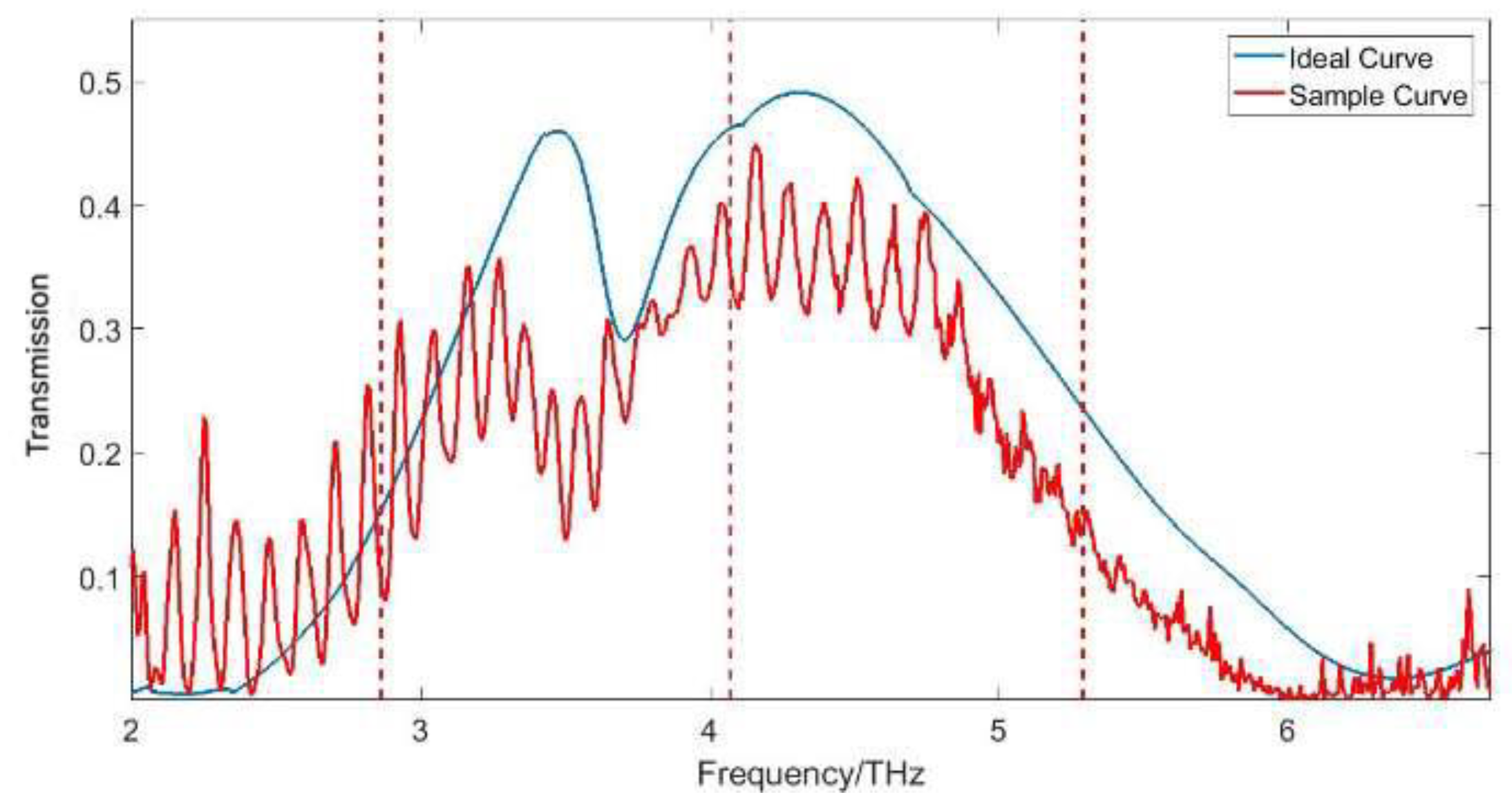
Figure 7, the corresponding frequency point at the highest transmission efficiency peak was close to 4.07 THz, and there was a significant transmission efficiency through near 6 THz. However, the spectral line of the test results exhibited a multi-spike shape because the terahertz wave was generated by the ultrafast laser-pulsed nonlinear crystal, which resulted in the selection of the terahertz signal by the cavity.
The peak structure of the above test data interfered with the calculation of 3-dB bandwidth to a certain extent, and also affected the quantitative comparison and analysis of experimental data and simulation data. In order to better perform data analysis, the measured results were polynomial-fitted, and the frequencies of the measured data were subdivided into many different frequency bands, where each frequency point corresponded to a transmission efficiency of the point, and the peak point of each pulse in each frequency band was selected and relabeled. Finally, the fitted envelope was compared with the pre-fit experimental value and the sample simulation optimization result, as shown in
Figure 8 and
Figure 9:
Figure 9 shows that the fitting curve agreed well with the sample test value, and the black fitting curve was completely in the middle of the red sample test data peak structure. In the measurement, the 3-dB bandwidth of the fitting curve was 2.18 THz, and the highest transmission efficiency was 38.1% in the main lobe. In the simulation, the 3-dB bandwidth was 2.19 THz, the highest transmission efficiency was 48.8%, as shown in
Table 1. The reason for the declining transmission efficiency in the measurement consists of three main parts: firstly, the absorption of the material itself caused the loss of the transmitted wave energy; secondly, for the incident beam, the incident condition was approximately of normal incidence; finally, the collimation beam expansion process was not performed, and there was a space transmission loss of the terahertz beam in the atmosphere.
5. Conclusions
In this paper, a rigorous coupled wave method and a genetic algorithm were used to propose a sub-wavelength binary simple periodic structure broadband filter design method which effectively realizes the filtering effect of broadband and high diffraction efficiency.
A center frequency of 4.07 THz was designed and filtered. A terahertz wideband filter with a frequency range of 2.94–5.27 THz was used to fabricate samples and tested using a binary optical process. The experimental results were consistent with the design results. As shown in
Table 2, the highest transmission efficiency in the main lobe was close to 50%, the highest transmittance of the reference double cone filter was increased by more than 10%, the 3-dB bandwidth was 2.33 THz, and the width was 0.13 THz. The influence of the variation of the grating structure parameters on the filtering effect of the filter was studied. The variation of the structural parameters had a great influence on the bandwidth. It was especially sensitive to the variation of the groove depth. Groove depth error control should be strengthened during the production. The fabrication error of the terahertz broadband filter structure parameters was analyzed, and the most suitable fabrication parameters are given: a grating period of 127.9 μm; a duty ratio of 0.414; and a grating groove depth of 29.60 μm. The allowable structural parameter redundancy ranges include: a grating period of 127.9 μm (±2.5 μm); a grating duty ratio of 0.414 (±0.002, minimum line width 53.0 μm, redundancy ±0.4 μm); and a grating groove depth of 29.6 ± 0.7 μm. The current production technology can fully realize the structure. The device was fabricated and tested with a 3-dB bandwidth of 2.18 THz, which is consistent with the design results, proving the correctness and feasibility of the design method. Additionally, there was a maximum transmission efficiency of 38.1% in the main lobe, which is less than the simulation and the reasons for this are discussed.
In this paper, a high-performance terahertz wideband filter was realized that overcomes the limitations of the current terahertz filters with a simple structure, a lower cost, and easier production. At the same time, tolerance analysis and manufacturing error analysis of the structural parameters were carried out. The actual sample preparation and performance test showed that the test results were consistent with the theoretical design, and can be applied in the fields of terahertz communication, imaging, and other fields.


