Path Planning under Force Control in Robotic Polishing of the Complex Curved Surfaces


Abstract
1. Introduction
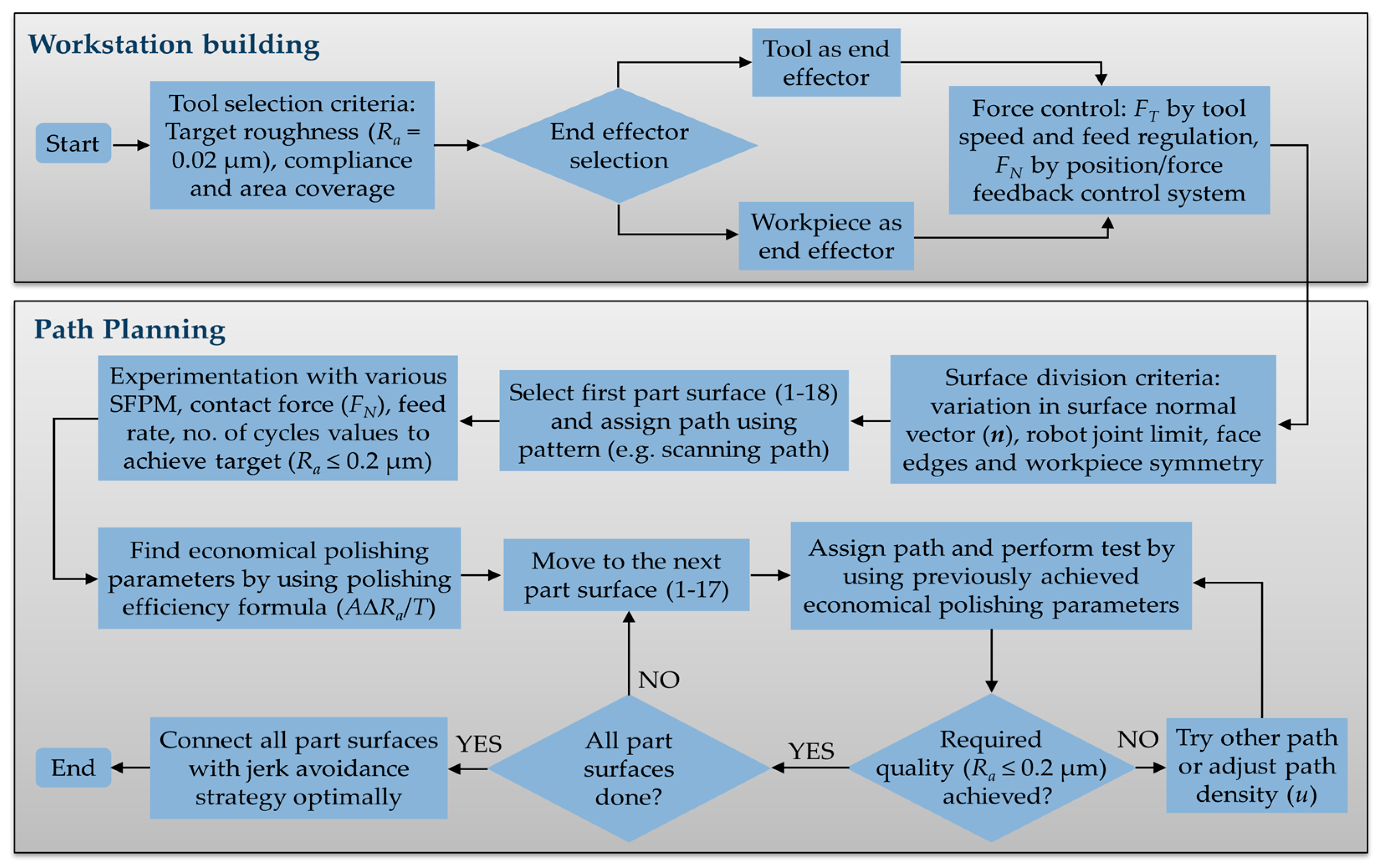
2. The Proposed Method
2.1. Workstation Building and Force Control
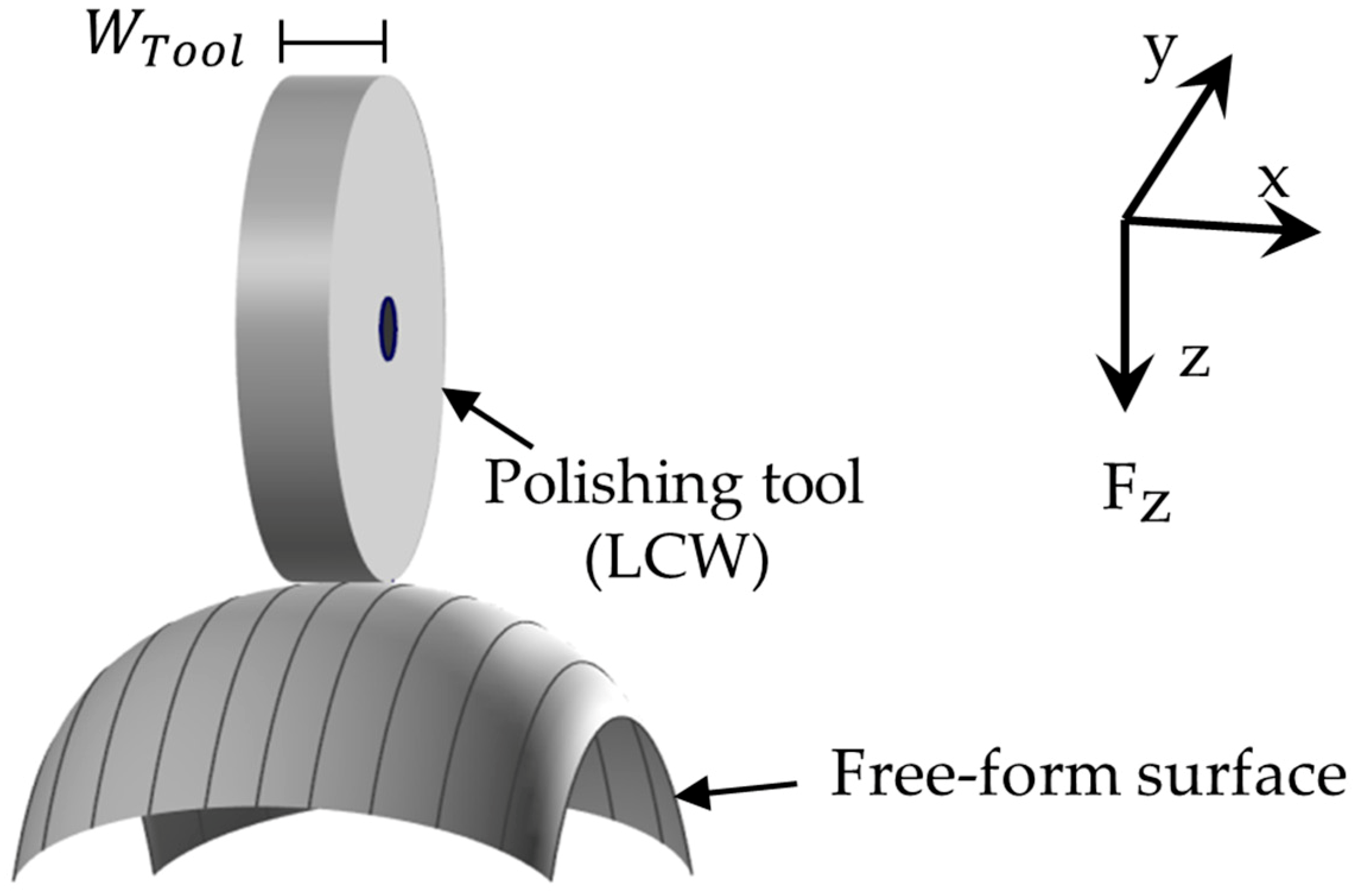
2.1.1. Polishing Tool and End Effector Selection
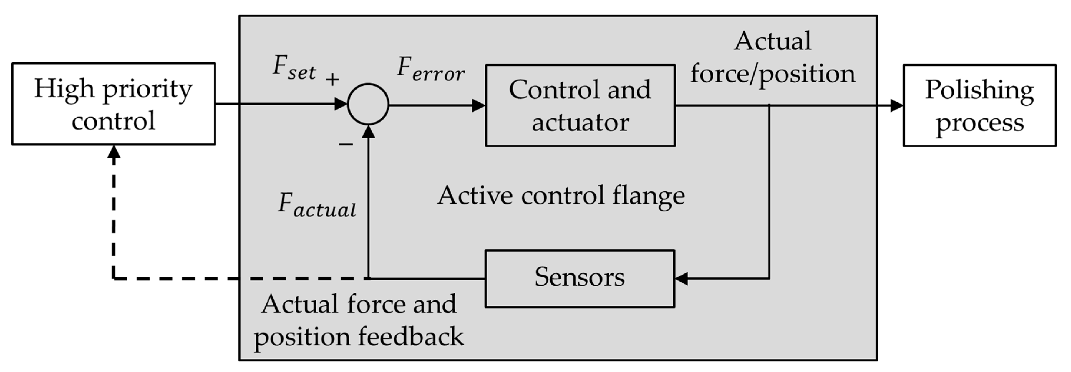
2.1.2. Force Control in Surface Polishing
Tangential Force Component Control
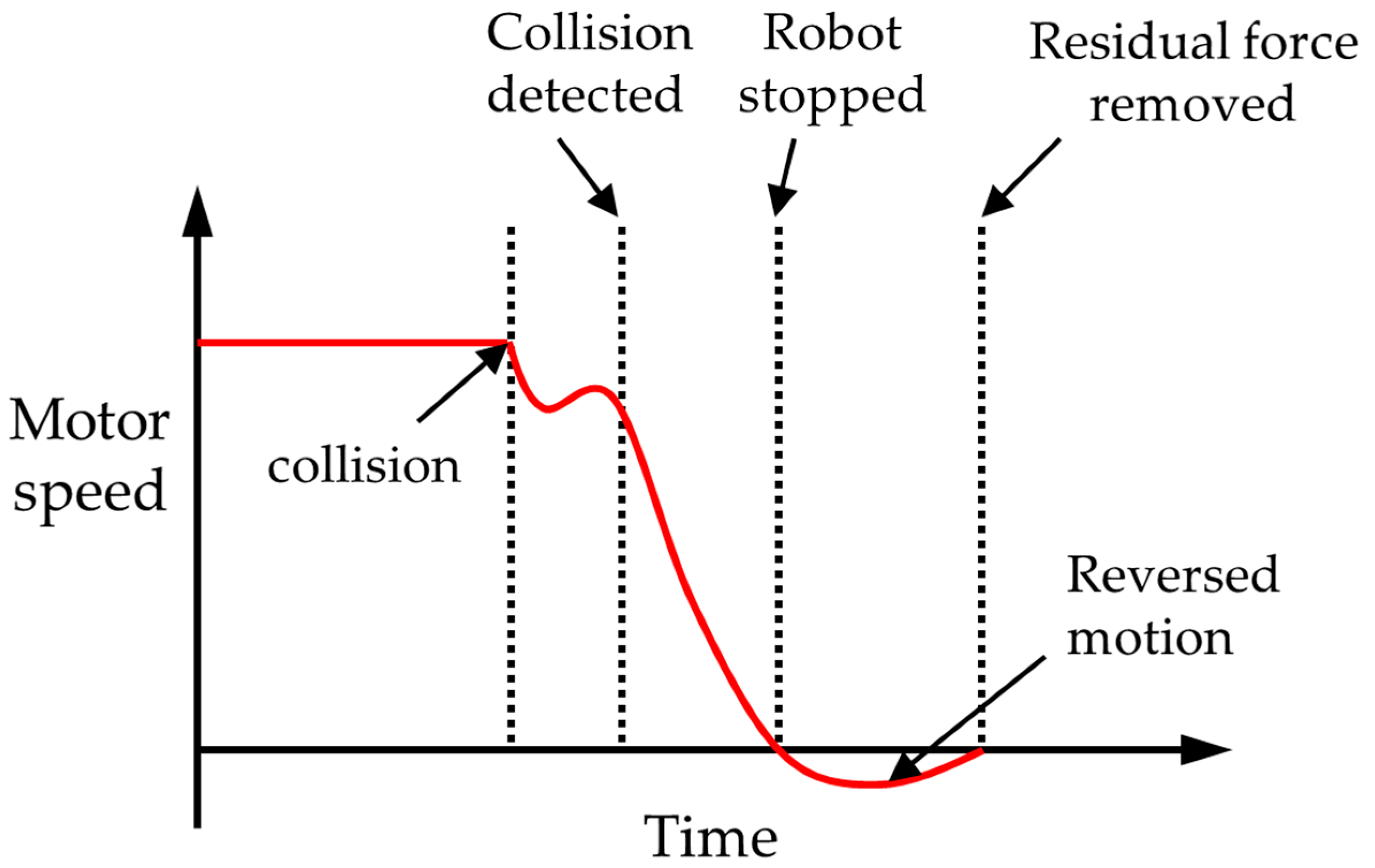
Normal Force Component Control
2.2. Tool Path Planning
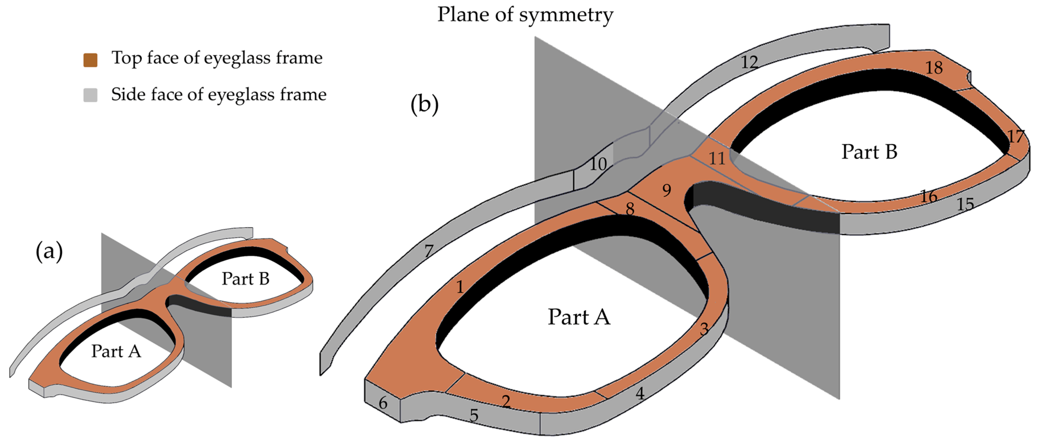
2.2.1. Surface Division
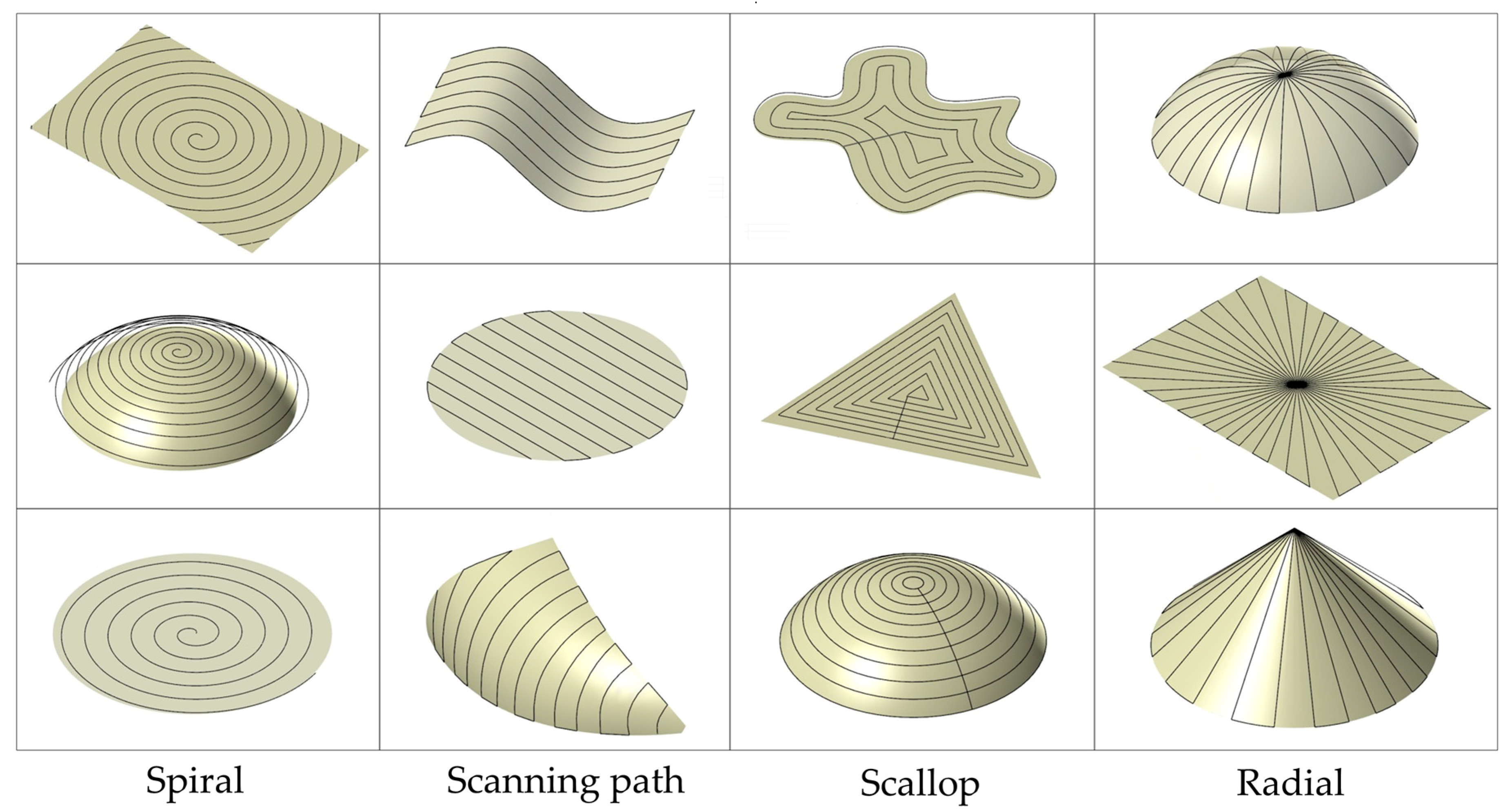
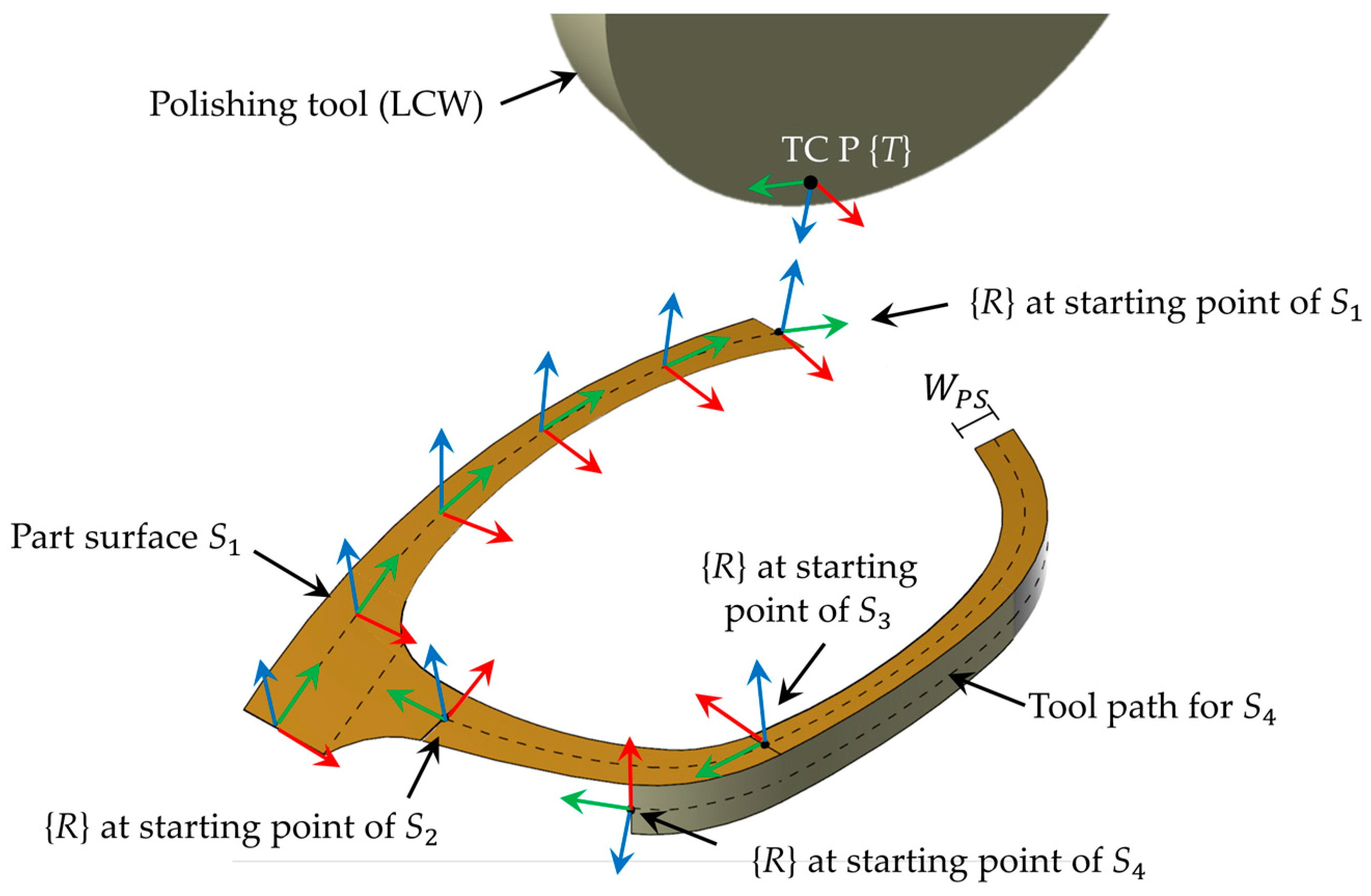
2.2.2. Tool Path Generation for Individual Part Surfaces
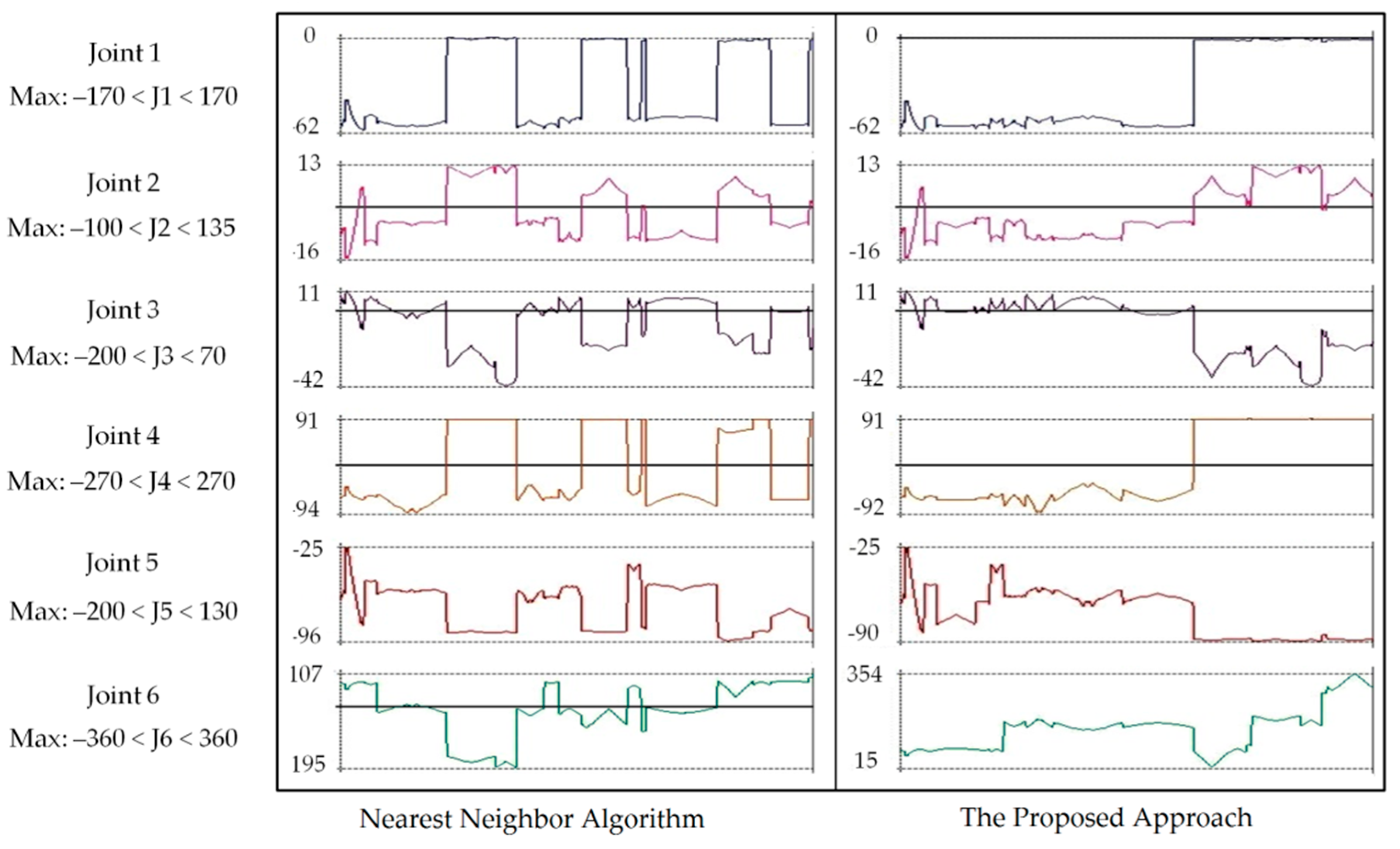
2.2.3. Tool Path Stitching
3. Results and Discussions
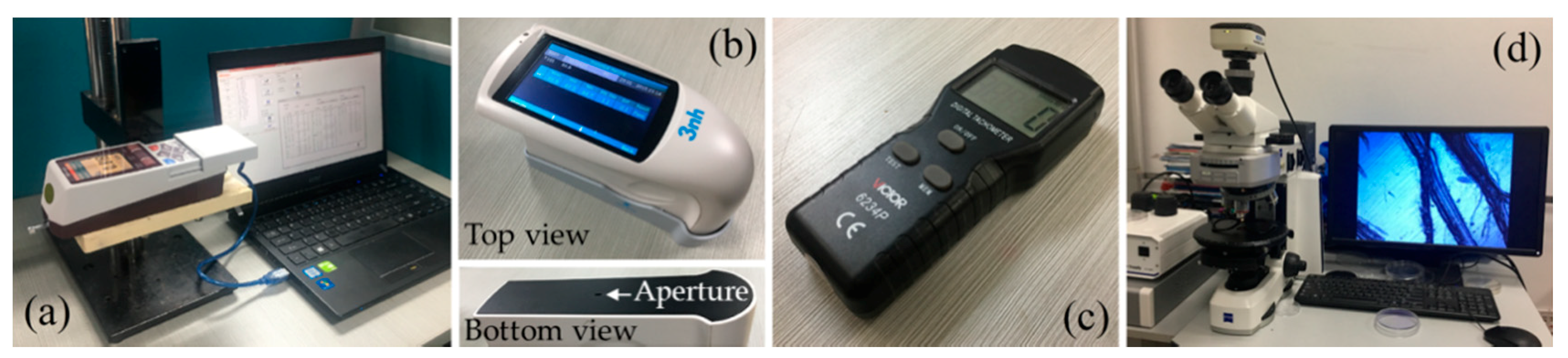
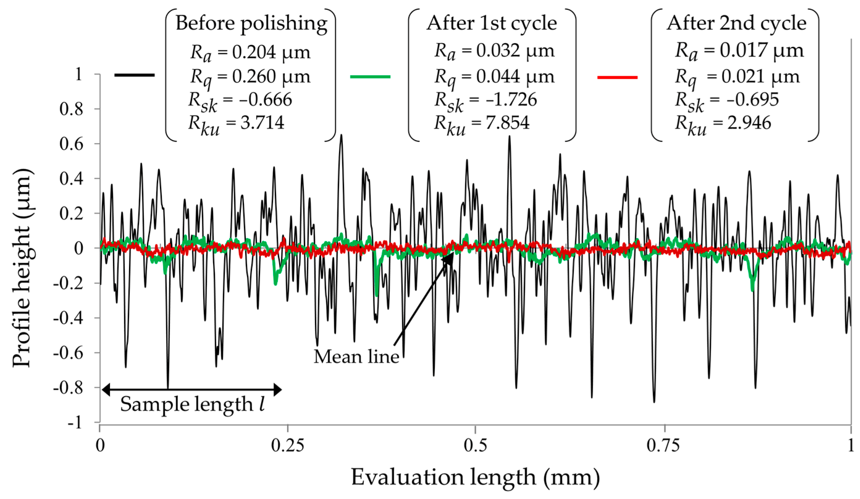
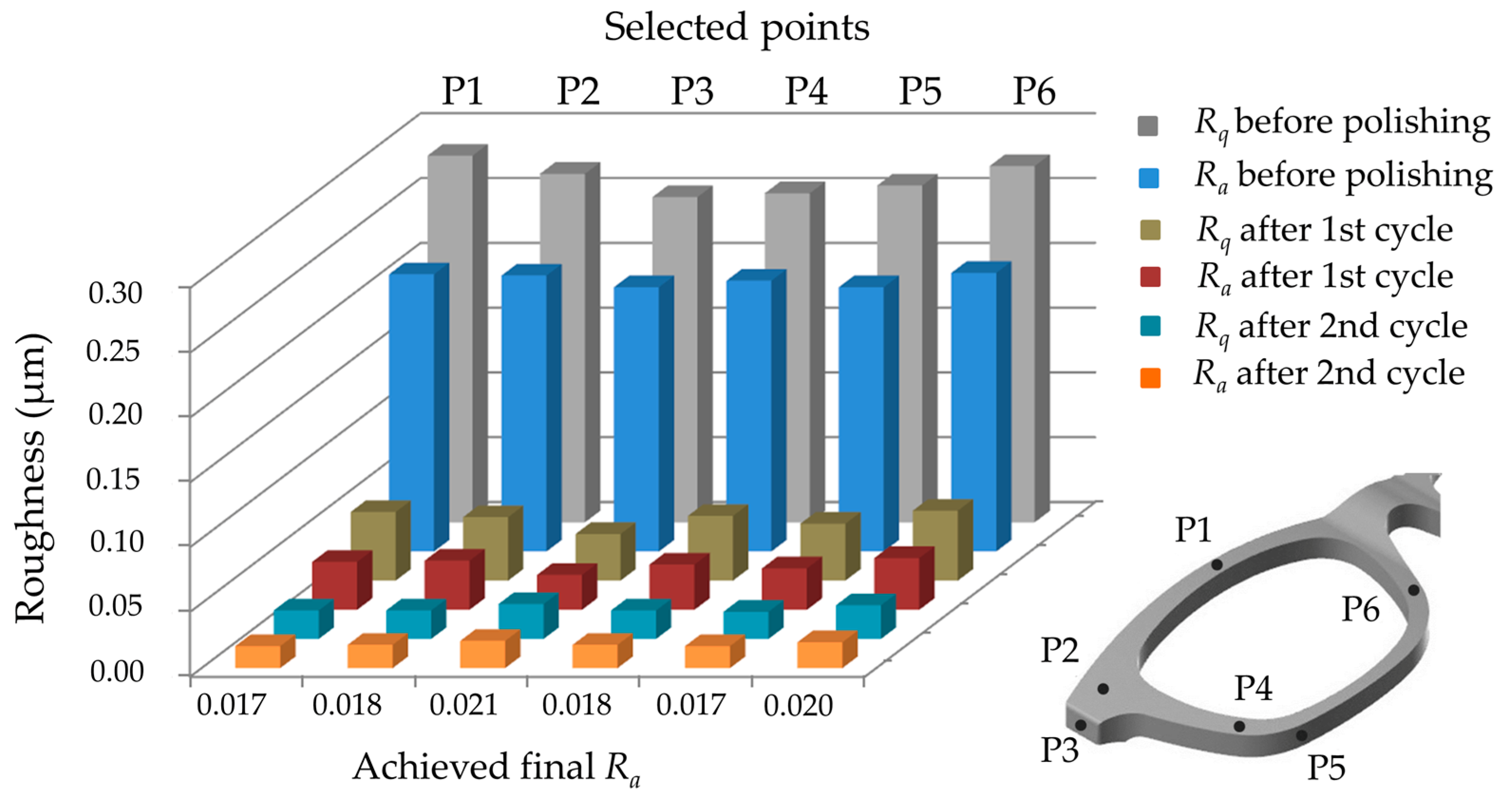
3.1. Surface Roughness
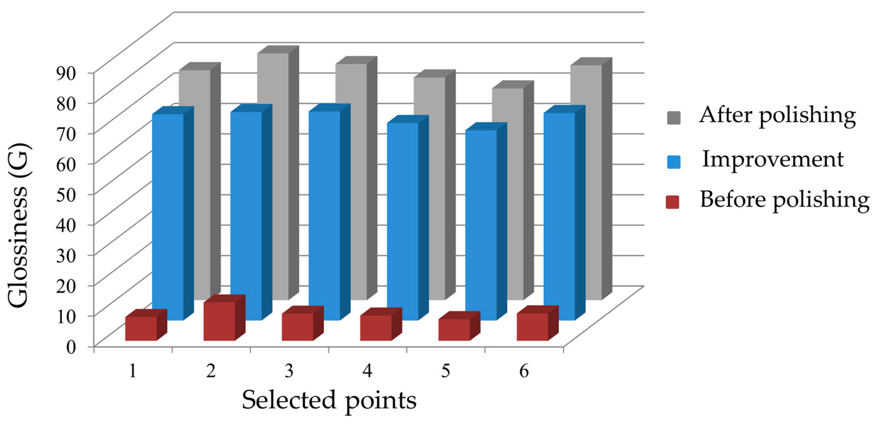
3.2. Glossiness
4. Conclusions
Author Contributions
Funding
Conflicts of Interest
References
- Ohnishi, O.; Suzuki, H.; Uhlmann, E.; Schröer, N.; Sammler, C.; Spur, G.; Weismiller, M. Chapter 4—Grinding. In Handbook of Ceramics Grinding and Polishing; Marinescu, I.D., Doi, T., Uhlmann, E., Eds.; William Andrew Publishing: Boston, MA, USA, 2015; pp. 184–186. [Google Scholar]
- Jakobsson, K.; Mikoczy, Z.; Skerfving, S. Deaths and tumours among workers grinding stainless steel: A follow up. Occup. Environ. Med. 1997, 54, 825–829. [Google Scholar] [CrossRef] [PubMed]
- Beaulieu, H.J. Silica Dust and Concrete Grinding and Polishing: The Tragedy & the Beauty. 2008. Available online: http://www.dcpolish.com/concretegrindingdanger.html (accessed on 15 May 2019).
- Grinding and Polishing Workers, Hand. Available online: https://www.bls.gov/oes/2018/may/oes519022.htm (accessed on 17 May 2019).
- Tam, H.Y.; Lui, O.C.; Mok, A.C. Robotic Polishing of Free-Form Surfaces Using Scanning Paths. J. Mater. Process. Technol. 1999, 95, 191–200. [Google Scholar] [CrossRef]
- Mizugaki, Y.; Sakamoto, M.; Sata, T. Fractal Path Generation for a Metal-Mold Polishing Robot System and Its Evaluation by the Operability. Cirp Ann. 1992, 41, 531–534. [Google Scholar] [CrossRef]
- Rososhansky, M.; Xi, F.J. Coverage Based Tool-Path Planning for Automated Polishing Using Contact Mechanics Theory. J. Manuf. Syst. 2011, 30, 144–153. [Google Scholar] [CrossRef]
- Kharidege, A.; Zhang, Y. A Practical Approach for Automated Polishing System of Free-Form Surface Path Generation Based on Industrial Arm Robot. Int. J. Adv. Manuf. Technol. 2017, 93, 3921–3934. [Google Scholar] [CrossRef]
- Mohsin, I.; He, K.; Du, R. Robotic Polishing of Free-Form Surfaces with Controlled Force and Effective Path Planning. In Proceedings of the ASME IMECE Conference, Pittsburgh, PA, USA, 9–15 November 2018; pp. 1–9. [Google Scholar]
- Oba, Y.; Kakinuma, Y. Tool Posture and Polishing Force Control on Unknown 3-Dimensional Curved Surface. In Proceedings of the ASME IMSEC Conference, Blackburg, VA, USA, 27 June–1 July 2016. [Google Scholar]
- Mohsin, I.; He, K.; Cai, J.; Chen, H.; Du, R. Robotic polishing with force controlled end effector and multi-step path planning. In Proceedings of the ICIA, Macau, China, 18–20 July 2017; pp. 344–348. [Google Scholar]
- Jinno, M.; Ozaki, F.; Yoshimi, T.; Tatsuno, K.; Takahashi, M.; Kanda, M.; Tamada, Y.; Nagataki, S. Development of a force controlled robot for grinding, chamfering and polishing. In Proceedings of the ICRA, Nagoya, Japan, 21–27 May 1995; pp. 1455–1460. [Google Scholar]
- Wang, C.; Wang, Z.; Wang, Q.; Ke, X.; Zhong, B.; Guo, Y.; Xu, Q. Improved semirigid bonnet tool for high-efficiency polishing on large aspheric optics. Int. J. Adv. Manuf. Technol. 2016, 88, 1607–1617. [Google Scholar] [CrossRef]
- Mohammad, A.E.; Hong, J.; Wang, D.; Guan, Y. Synergistic integrated design of an electrochemical mechanical polishing end-effector for robotic polishing applications. Robot. Comput. Integr. Manuf. 2019, 55, 65–75. [Google Scholar] [CrossRef]
- Perez-Vidal, C.; Gracia, L.; Sanchez-Caballero, S.; Solanes, J.E.; Saccon, A.; Tornero, J. Design of a polishing tool for collaborative robotics using minimum viable product approach. Int. J. Comput. Integr. Manuf. 2019, 32, 848–857. [Google Scholar] [CrossRef]
- Arunachalam, A.P.; Idapalapati, S.; Subbiah, S. Multi-criteria decision making techniques for compliant polishing tool selection. Int. J. Adv. Manuf. Technol. 2015, 79, 519–530. [Google Scholar] [CrossRef]
- Zhan, J. An improved polishing method by force controlling and its application in aspheric surfaces ballonet polishing. Int. J. Adv. Manuf. Technol. 2013, 68, 2253–2260. [Google Scholar] [CrossRef]
- Liu, Y.; Zhang, Y. Toward Welding Robot with Human Knowledge: A Remotely-Controlled Approach. IEEE Trans. Autom. Sci. Eng. 2015, 12, 769–774. [Google Scholar] [CrossRef]
- Hertling, P.; Hog, L.; Larsen, R.; Perram, J.W.; Petersen, H.G. Task curve planning for painting robots. I. Process modeling and calibration. IEEE Trans. Robot. Autom. 1996, 12, 324–330. [Google Scholar] [CrossRef]
- Yuan, P.; Wang, Q.; Shi, Z.; Wang, T.; Wang, C.; Chen, D.; Shen, L. A micro-adjusting attitude mechanism for autonomous drilling robot end-effector. Sci. China Inf. Sci. 2014, 57, 1–12. [Google Scholar] [CrossRef]
- Gu, S.S.; Yang, C.Y.; Fu, Y.C.; Ding, W.F.; Huang, D.S. Grinding Force and Specific Energy in Plunge Grinding of 20crmnti with Monolayer Brazed Cbn Wheel. Mater. Sci. Forum 2014, 770, 34–38. [Google Scholar] [CrossRef]
- Bifano, T.G.; Fawcett, S.C. Specific grinding energy as an in-process control variable for ductile-regime grinding. Precis. Eng. 1991, 13, 207–216. [Google Scholar] [CrossRef]
- Linke, B.S.; Garretson, I.; Torner, F.; Seewig, J. Grinding Energy Modeling Based on Friction, Plowing, and Shearing. J. Manuf. Sci. Eng. 2017, 139, 1–11. [Google Scholar] [CrossRef]
- Nagata, F.; Hase, T.; Haga, Z.; Omoto, M.; Watanabe, K. CAD/CAM-based position/force controller for a mold polishing robot. Mechatronics 2007, 17, 207–216. [Google Scholar] [CrossRef]
- Mendes, N.; Neto, P. Indirect adaptive fuzzy control for industrial robots: A solution for contact applications. Expert Syst. Appl. 2015, 42, 8929–8935. [Google Scholar] [CrossRef]
- Zhang, J.; Liu, G.; Zang, X.; Li, L. A hybrid passive/active force control scheme for robotic belt grinding system. In Proceedings of the ICMA, Harbin, China, 7–10 August 2016; pp. 737–742. [Google Scholar]
- Craig, J.J. Introduction to Robotics Mechanics and Control, 3rd ed.; Horton, M.J., Ed.; Pearson Education, Inc. Pearson Prentice Hall: Upper Saddle River, NJ, USA, 2005; pp. 62–64, 148–151. [Google Scholar]
- Zhao, Q.; Zhang, L.; Han, Y.; Fan, C. Polishing path generation for physical uniform coverage of the aspheric surface based on the Archimedes spiral in bonnet polishing. Proc. Inst. Mech. Eng. Part B J. Eng. Manuf. 2019, 233, 0954405419838655. [Google Scholar] [CrossRef]
- Tsai, M.; Chang, J.-L.; Haung, J.-F. Development of an automatic mold polishing system. IEEE Trans. Autom. Sci. Eng. 2005, 2, 393–397. [Google Scholar] [CrossRef]
- Tsai, M.J.; Huang, J.F. Efficient automatic polishing process with a new compliant abrasive tool. Int. J. Adv. Manuf. Technol. 2006, 30, 817–827. [Google Scholar] [CrossRef]
- Han, G.; Sun, M. Compound control of the robotic polishing process basing on the assistant electromagnetic field. In Proceedings of the IEEE International Conference on Mechanical and Automation, Changchun, China, 9–12 August 2009; pp. 1551–1555. [Google Scholar]
- Donelan, P.S. Singularity of robot manipulators. In Singularity Theory; Chéniot, D., Dutertre, N., Eds.; CIRM: Marseille, France, 2007; pp. 189–217. [Google Scholar]
- Mehrban, M.; Kouravand, S.; Rezazadeh, G.; Donyavi, A. Application of Full Factorial Design Method in MEMS Capacitive Thermal Sensor Sensitivity. In Proceedings of the IEEE International Conference on Semiconductor Electronics, Kuala Lumpur, Malaysia, 29 October–1 December 2006; pp. 172–176. [Google Scholar]
- Valizadeh, A.; Akbarzadeh, A.; Heravi, M.H.T. Effect of structural design parameters of a six-axis force/torque sensor using full factorial design. In Proceedings of the 3rd RSI International Conference on Robotics and Mechatronics (ICROM), Tehran, Iran, 7–9 October 2015; pp. 789–793. [Google Scholar]
- Li, H.; Li, X.; Tian, C.; Yang, X.; Zhang, Y.; Liu, X.; Rong, Y. The simulation and experimental study of glossiness formation in belt sanding and polishing processes. Int. J. Adv. Manuf. Technol. 2016, 90, 199–209. [Google Scholar] [CrossRef]
- Li, S.; Manabe, Y.; Chihara, K. Accurately estimating reflectance parameters for color and gloss reproduction. Comput. Vis. Image Underst. 2009, 113, 308–316. [Google Scholar] [CrossRef]
- Yonehara, M.; Matsui, T.; Kihara, K.; Isono, H.; Kijima, A.; Sugibayashi, T. Experimental Relationships between Surface Roughness, Glossiness and Color of Chromatic Colored Metals. Mater. Trans. 2004, 45, 1027–1032. [Google Scholar] [CrossRef]
- Bennett, H.E.; Porteus, J.O. Relation between Surface Roughness and Specular Reflectance at Normal Incidence. J. Opt. Soc. Am. 1961, 51, 123–129. [Google Scholar] [CrossRef]


| Exp. No. | Feed Rate (mm/s) | No. of Cycle | SFPM | Ra | Exp. No. | Feed Rate (mm/s) | No. of Cycle | SFPM | Ra | ||
|---|---|---|---|---|---|---|---|---|---|---|---|
| 1 | 15 | 1 | 2950 | 0.032 | 13.06 | 16 | 45 | 2 | 3750 | 0.019 | 15.50 |
| 2 | 15 | 1 | 3750 | 0.020 | 13.97 | 17 | 45 | 3 | 2950 | 0.017 | 08.80 |
| 3 | 15 | 2 | 2950 | 0.017 | 07.07 | 18 | 45 | 3 | 3750 | 0.017 | 08.80 |
| 4 | 15 | 2 | 3750 | 0.017 | 07.07 | 19 | 60 | 1 | 2950 | 0.051 | 28.45 |
| 5 | 15 | 3 | 2950 | 0.015 | 04.03 | 20 | 60 | 1 | 3750 | 0.039 | 30.55 |
| 6 | 15 | 3 | 3750 | 0.016 | 04.01 | 21 | 60 | 2 | 2950 | 0.028 | 16.23 |
| 7 | 30 | 1 | 2950 | 0.033 | 22.59 | 22 | 60 | 2 | 3750 | 0.025 | 16.50 |
| 8 | 30 | 1 | 3750 | 0.023 | 23.86 | 23 | 60 | 3 | 2950 | 0.021 | 09.26 |
| 9 | 30 | 2 | 2950 | 0.017 | 12.30 | 24 | 60 | 3 | 3750 | 0.020 | 09.31 |
| 10 | 30 | 2 | 3750 | 0.017 | 12.30 | 25 | 75 | 1 | 2950 | 0.070 | 26.36 |
| 11 | 30 | 3 | 2950 | 0.015 | 06.97 | 26 | 75 | 1 | 3750 | 0.053 | 29.47 |
| 12 | 30 | 3 | 3750 | 0.016 | 06.94 | 27 | 75 | 2 | 2950 | 0.041 | 15.83 |
| 13 | 45 | 1 | 2950 | 0.038 | 27.97 | 28 | 75 | 2 | 3750 | 0.036 | 16.29 |
| 14 | 45 | 1 | 3750 | 0.029 | 29.44 | 29 | 75 | 3 | 2950 | 0.028 | 09.21 |
| 15 | 45 | 2 | 2950 | 0.020 | 15.43 | 30 | 75 | 3 | 3750 | 0.023 | 09.45 |
| Polishing Cycle | Selected Tool | Polishing Material | SFPM (3750) | Feed Direction | Contact Force FN (N) | Feed Rate (mm/s) | |
|---|---|---|---|---|---|---|---|
| Wheel Diameter (mm) | Wheel Speed (rpm) | ||||||
| 1 | LCW | Dry finish Paste (P126) | 152 | 2387 | Against wheel rotation | 1 | 45 |
| 2 | In direction of wheel rotation | ||||||
| S. No. | Mean Value | Max. Value | Min. Value | Standard. Deviation | Difference | Mean Glossiness |
|---|---|---|---|---|---|---|
| 01 | 78.1 | 78.1 | 78.1 | 0.0 | 0.1 | 77.6 |
| 02 | 77.4 | 78.1 | 76.7 | 0.7 | −0.6 | |
| 03 | 77.7 | 78.3 | 76.7 | 0.7 | −0.3 | |
| 04 | 77.0 | 78.3 | 74.9 | 1.3 | −1.0 | |
| 05 | 77.6 | 80.0 | 74.9 | 1.7 | −0.4 |
© 2019 by the authors. Licensee MDPI, Basel, Switzerland. This article is an open access article distributed under the terms and conditions of the Creative Commons Attribution (CC BY) license (http://creativecommons.org/licenses/by/4.0/).
Share and Cite
Mohsin, I.; He, K.; Li, Z.; Du, R. Path Planning under Force Control in Robotic Polishing of the Complex Curved Surfaces. Appl. Sci. 2019, 9, 5489. https://doi.org/10.3390/app9245489
Mohsin I, He K, Li Z, Du R. Path Planning under Force Control in Robotic Polishing of the Complex Curved Surfaces. Applied Sciences. 2019; 9(24):5489. https://doi.org/10.3390/app9245489
Chicago/Turabian StyleMohsin, Imran, Kai He, Zheng Li, and Ruxu Du. 2019. "Path Planning under Force Control in Robotic Polishing of the Complex Curved Surfaces" Applied Sciences 9, no. 24: 5489. https://doi.org/10.3390/app9245489
APA StyleMohsin, I., He, K., Li, Z., & Du, R. (2019). Path Planning under Force Control in Robotic Polishing of the Complex Curved Surfaces. Applied Sciences, 9(24), 5489. https://doi.org/10.3390/app9245489