Article

An Image-Processing Method for Extracting Kinematic Characteristics of Droplets during Pulsed GMAW

College of Materials Science and Technology, Nanjing University of Aeronautics and Astronautics, Nanjing 210016, China
*
Author to whom correspondence should be addressed.
Appl. Sci. 2019, 9(24), 5481; https://doi.org/10.3390/app9245481
Submission received: 8 November 2019 / Revised: 29 November 2019 / Accepted: 10 December 2019 / Published: 13 December 2019
(This article belongs to the Section Optics and Lasers)

Abstract

:

Featured Application

In this paper, the proposed monitoring system and image processing algorithm give a simple and feasible way to investigate kinematic characteristics, which can provide a new method for possible applications in studying mathematic descriptions of droplet flight trajectory and developing a precise automatic welding system.

Abstract

Pulsed gas metal arc welding (GMAW) is widely applied in industrial manufacturing. The use of pulsed GMAW was found superior to the traditional direct-current (DC) welding method with respect to spatter, welding performance, and adaptability of all-position welding. These features are closely related to the special pulsed projected metal transfer process. In this paper, a monitoring system based on a high-speed camera and laser backlight is proposed. High-quality images with clear droplets and a translucent arc can be obtained at the same time. Furthermore, a novel image-processing algorithm is proposed in this paper, which was successfully applied to remove the interference of the arc. As a result, the edge and region of droplets were precisely extracted, which is not possible using only the threshold method. Based on the algorithm, centroid coordinates of undetached and detached droplets can be calculated, and more parameters of the kinematic characteristics of droplets can be derived, such as velocity, acceleration, external force, and momentum. The proposed monitoring system and image-processing algorithm give a simple and feasible way to investigate kinematic characteristics, which can provide a new method for possible applications in studying mathematic descriptions of droplet flight trajectory and developing a precise automatic welding system.

1. Introduction

As one of the most efficient welding methods, gas metal arc welding (GMAW) is widely used in industrial production due to the large range of controllable heat input levels [1,2,3]. With the rapid promotion of automation in the welding industry, the traditional direct-current (DC) welding method at constant voltage fails to meet the increasing manufacturing requirements; hence, pulsed GMAW was developed recently, and it is especially used in robotic welding systems [4].
A special pulsed projected metal transfer process plays an important role in the stability of pulsed GMAW [5,6,7]. Under the periodic action of a pulse current, the droplets periodically transit to the molten pool, the speed of which has a great effect on the welding quality. As a result, a better adaptability of all-position welding can be obtained during the pulsed GMAW process [8,9]. Therefore, it is significant to observe and study the metal transfer process of pulsed GMAW.
In addition, under the drive of intelligent manufacturing, automatic welding technology is gaining importance. As a powerful tool to extract information from digital images, image processing is applied in automatic welding equipment to monitor the welding process and amend parameters automatically [10,11,12]. It is of great significance to obtain intuitive information of the metal transfer process using image-processing technology to improve the quality of pulsed GMAW. Many recent investigations focused on the mode of metal transfer and tried to determine the mathematic description of droplet flight trajectory or kinematic characteristics, such as droplet size and velocity [13,14,15,16]. Both arc and droplet behaviors are necessary for studying metal transfer. However, it is difficult to obtain high-quality pictures of the arc and clear droplets at the same time, and the extraction of droplet information is not precise enough due to the interference of the bright arc.
Thus, in this paper, a monitoring system of the metal transfer process is proposed to acquire clear images during pulsed GMAW. Furthermore, a novel image-processing algorithm is designed to recognize the edge and centroid coordinates of a droplet automatically from the metal transfer image. To this end, kinematic characteristics of droplets can be extracted based on the proposed algorithm for possible applications in revealing the droplet transfer mode and developing precise automatic welding systems.

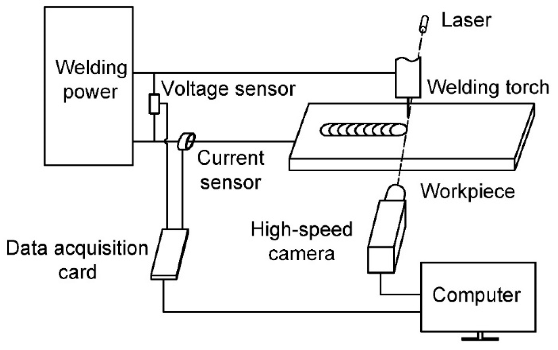
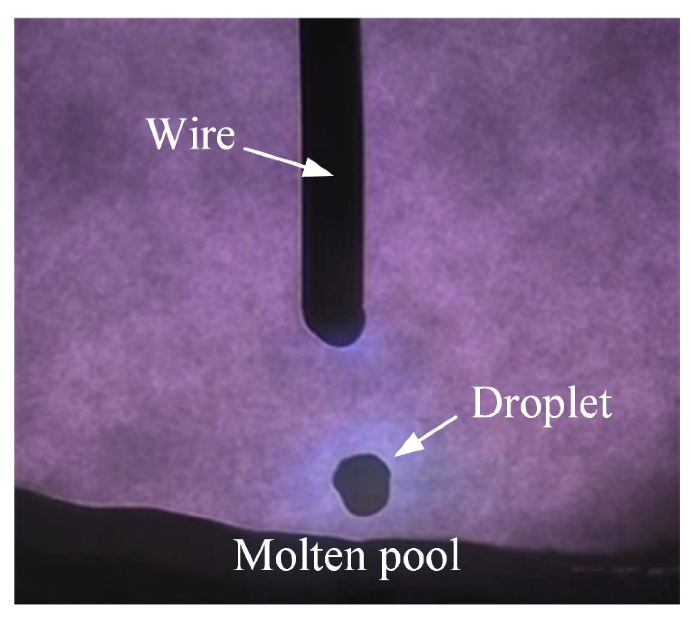
2. Experimental System and Welding Conditions

Figure 1 shows the GMAW system that can realize synchronous voltage, current, and image signal acquisition. Considering that the frequency of arc behavior and droplet transfer is pretty high in GMAW, a high-speed camera at 10,000 fps was used in this study to catch detailed images of the process. However, the welding arc cannot be photographed without filter lens protection. Otherwise, the extremely bright arc could cause huge interference in the images and even damage the photosensitive elements of camera. The brightness of the arc should be filtered to an appropriate range. Depending on the spectrogram of a welding arc, the energy of arc light in the infrared band is relatively weak [17]. Thus, a narrow-band filter centered at 850 nm was placed in the lens, and a laser light with a wavelength of 850 nm was used as a backlight to enhance the background brightness and magnify the contrast of images.
In addition, an adjustable ND (neutral density) filter was added in front of the lens. The filter is composed of a pair of polarizers. According to Malus’s law, light intensity can be adjusted by changing the relative angles θ of the two polarizers [18]. Furthermore, because of different response characteristics of visible light and infrared light, this ND filter has a significant effect on visible light reduction but not the 850-nm infrared laser [19]. As a result, the intensity of arc light in the image can be strengthened or weakened, while the intensity of the laser background merely changes with the ND filter.
Two groups of images under the same single typical pulse current but different polarization angle of the ND filter are shown in Figure 2. Arc behavior can clearly be seen in Figure 2b (translucent arc). With the increase in current, the arc becomes brighter; however, the droplet is covered by the arc at peak current. After that, the contour of droplet surrounded by the translucent arc becomes clear when the brightness of the arc decreases. In contrast, a clear contour of the droplet but no arc can be found in Figure 2c (transparent arc). Arc light is totally removed by the narrow-band filter and ND filter.
Arc behavior is necessary for studying metal transfer, as the droplet is mainly pushed into the molten pool by the arc force [20]. For the image processing of droplets, it is not expected to have the interference of arc light in images, as seen in Figure 2b. Thus, Figure 2c, which filters all the arc light, would have an advantage in the image processing. However, the arc does play a significant role in droplet transfer. Although a clear droplet profile and less interference of arc light can be found in Figure 2c, the key information of the arc for analyzing the droplet transfer is lost.
Therefore, for the research of droplet transfer, it is a better choice to keep the information of the arc and droplet at the same time in images. From this point of view, Figure 2b, which has both a translucent arc and clear droplet, is more appropriate for comprehensively studying droplet transfer. As a result, images with a translucent arc like Figure 2b were selected as the study object of the image processing in this paper.
The ER50-6 wire of 1.2 mm diameter was used, and the CTWD (contact tube-to-work distance) was selected as 18 mm. Additionally, Table 1 shows the other welding conditions of the pulsed GMAW.

3. Extraction of Droplet Region by Image Processing

In this part, images with a translucent arc such as that shown in Figure 2b were selected as the study object of the image processing. Certainly, the interference of the arc in images undoubtedly increases the difficulty of image processing. In order to solve this problem successfully, a droplet region-extracting algorithm based on image processing is proposed. By observing the recorded video, the droplet transfer process in pulsed GMAW can be divided into the two following periods:
  • The period with an undetached droplet;
  • The period with a detached droplet.
When in the period with an undetached droplet, the droplet is yet to detach from the wire, but eventually detaches under the actions of arc force and heat. Then, the droplet moves into the period with a detached droplet, during which the droplet is disconnected from the wire and transferred to the molten pool at a certain speed.

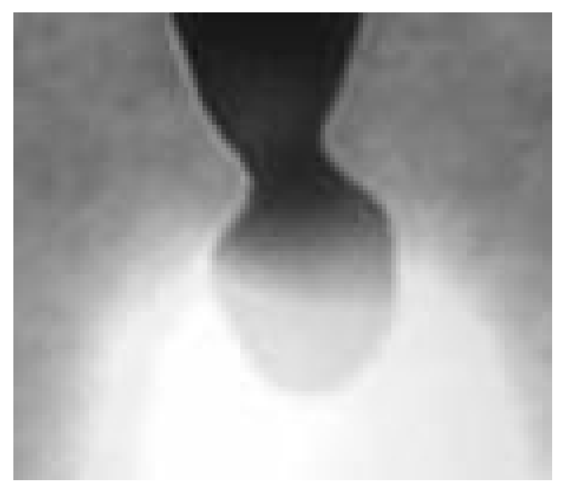
3.1. The Period with an Undetached Droplet

The droplet and wire are still connected in the period with an undetached droplet, as seen in Figure 3. As observed in Figure 2b, the droplet is disconnected from the wire at the neck. That is to say, the detached droplet comes from the part below the minimum neck of the droplet in the period with an undetached droplet. Thus, in this study, the droplet was divided at the minimum diameter of the neck. The residual droplet part of the solid wire was above the dividing line, while the droplet below the dividing line was taken as the research object for the subsequent extraction of kinematic characteristics. For the convenience of study, the droplet below the dividing line is called the target droplet in this paper.
Based on the above ideas, the following image-processing scheme is proposed for the recognition of the target droplet in the period with an undetached droplet: (1) image enhancement; (2) position identification of the minimum diameter of the neck; (3) droplet cutting and recognition.

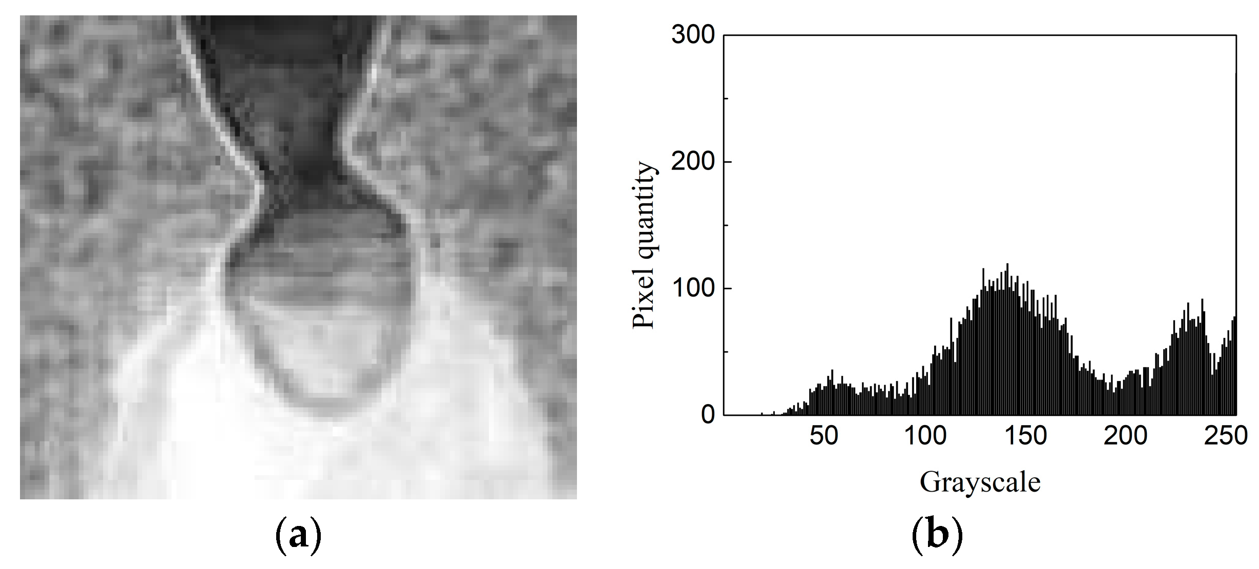
3.1.1. Image Enhancement

The image color does not affect the droplet position information. To simplify the process, the first step was to convert the color image into a grayscale image. Taking Figure 3 as an example, Figure 4 displays the grayscale of the original image after conversion. Additionally, the image around the droplet in Figure 4 was selected as the region of interest (ROI) to highlight the key points and further simplify the process (see Figure 5).
The method of thresholding is a widely used method in image segmentation, which sets the gray value “f(x)” of pixel “x” to the minimum or the maximum by comparing it with the threshold “T” (see Equation (1)). The purpose here is to distinguish the wire and droplet from the background in Figure 5. Therefore, the intermediate gray value of the wire and background was selected as the threshold, and the effect of image segmentation is shown in Figure 6a. It can be found that only the wire and the part of the droplet without the arc can be separated from the background. However, the part of the droplet with arc is lost in the background, because of the interference of the bright arc. In addition, the method of Otsu’s adjustable thresholding [21] was also applied to Figure 5, and the effect is displayed in Figure 6b. The result shows that the wire cannot be separated from the background by using the method of adjustable thresholding.
It is not possible to remove the interference of the arc and obtain a high-quality image of the segmentation effect using only the threshold method. To solve this problem, an algorithm based on the histogram image balance method is proposed.
f ( x ) = { 0 ( x < T ) 255 ( x > T ) .
Next, different edge operators were applied in the ROI region (Figure 5) in order to try to extract the droplet edge, and the processing results are shown in Figure 7. The edge of the gray image is often the place where the gray value of the pixel changes suddenly. The typical operators of edge recognition mainly include first-order differential edge operators (like the Sobel operator [22], Prewitt operator [23], Roberts operator [24]) and second-order differential edge operators (like the Laplacian of Gaussian (LoG) operator [25], Canny operator [26]). It can be seen that, due to the interference of the arc, the Sobel operator, Prewitt operator, and Roberts operator only extracted the upper half of the droplet, and the information of the lower half was lost, which is obviously not applicable. The LoG operator and Canny operator basically recognized the whole picture of the droplet, but a small part of the area on the left side of the droplet was still missing, leading to an incomplete outline. Therefore, before using the LoG operator and Canny operator to extract the droplet edge, a suitable image enhancement method should be applied to get a more continuous and complete edge.
Edge recognition of the lower part of droplet failed due to the high brightness of the arc, as shown in Figure 7. By observing the gray histogram of the ROI in Figure 8, lots of detail in the image was lost, because the high-brightness part (grayscale near 250) and the low-brightness part (grayscale near 120) were both excessively centralized. For the sake of magnifying detail and contrast, the method of adaptive histogram equalization was utilized in the ROI, followed by gamma transformation to compress the lower gray level and stretch the higher gray level [27] (see Figure 9 and Figure 10).
After the above image enhancement processing, the LoG operator and Canny operator were used to distinguish the edge of the droplet in the processed image. As we can see in Figure 11a, although the discontinuous part of the lower left edge of droplet was repaired, the lower right edge of the droplet was broken by the LoG operator. For comparison, a clear and complete edge of the droplet can be seen in Figure 11b using the Canny operator. The Canny operator showed better performance than the LoG operator here.
As Figure 12 shows, using the above enhancement algorithm and Canny edge operator to process Figure 4, better contrast and continuity of the droplet edge can also be obtained.
In conclusion, image enhancement can enlarge the contrast and improve the detail of the arc and droplet, while the Canny operator can better identify the edge of the droplet, obtaining a clear and continuous edge. Above all, the image enhancement algorithm during the period with an undetached droplet can be summarized as follows:
  • Step 1: Grayscale transformation;
  • Step 2: ROI selection;
  • Step 3: Edge operator test;
  • Step 4: Adaptive histogram equalization;
  • Step 5: Gamma transformation;
  • Step 6: Edge operator verification.

3.1.2. Position Identification of the Minimum Diameter of the Neck

In the period with an undetached droplet, the droplet and wire are still connected as a whole. As a result, the region of the droplet needs to be segmented artificially, which is the purpose of identifying the position of the minimum diameter of the droplet neck. Position identification of the minimum diameter of the neck is the premise of image cutting and detaching the region of the target droplet.
Firstly, a new ROI near neck in Figure 3 was selected, which is the rectangle box region shown in Figure 13. Secondly, distances from all points in one edge of the neck to the other edge in this ROI were calculated. The minimum distance was the minimum diameter of neck, while the corresponding two points were the endpoints of the minimum diameter.
Figure 14 shows the binary image of the ROI after the image enhancement mentioned in Section 3.1.1 (adaptive histogram equalization and gamma transformation) and Canny operator recognition. It can be found that the two edges of the neck extended continuously from the top to the bottom of the image. If the pixels in the first line and last line of the binary image were replaced with white pixels, the region of the neck could be sealed by white pixels. Thus, the region of neck could be filled with white pixels by using a hole-filling algorithm [28], and the result is displayed in Figure 15.
The whole white neck in Figure 15b could be extracted by finding the largest connected domain, and the extraction result is shown in Figure 16a. As a result, the background was divided into two parts. Next, these two parts were turned into white pixels, while the original white pixels were turned into black pixels. Thus, the edge of the two half areas could be identified by the Canny operator, so as to separate the two edges of the neck, as shown in Figure 16.
In order to calculate the minimum distance between the two edges, the algorithm used in this study calculated all the distances from each pixel on one edge to each pixel on the other (Equation (2)) and found the minimum Lmin by comparison (Equation (3)).
d i , j = ( x i x j ) 2 + ( y i y j ) 2 .
L min = min ( d i , j ) .
In the two equations, di,j is the distance from pixel i on the left edge to pixel j on the right edge. xi and yi are the abscissa and ordinate, respectively, of pixel i, while xj and yj are the abscissa and ordinate of point j. If i = I and j = J when di,j is the minimum value, then the two edge coordinates of the minimum diameter of neck are (xI, yI) and (xJ, yJ). However, (xI, yI) and (xJ, yJ) are the coordinates of the ROI in Figure 14, which can be further converted into the coordinates (XI, YI) and (XJ, YJ) of the original image to locate the position of the minimum diameter of the droplet neck.
In conclusion, for position identification of the minimum diameter of the neck, the key point is to divide the two edges of the neck and find the minimum distance of the pixels on the two edges. Above all, the position identification of the minimum diameter of the neck during the period with an undetached droplet can be summarized as follows:
  • Step 1: ROI selection near the neck;
  • Step 2: Edge recognition;
  • Step 3: Sealing the area of the neck;
  • Step 4: Filling the area of the neck;
  • Step 5: Neck recognition;
  • Step 6: Image inversion;
  • Step 7: Identification of the left and right background;
  • Step 8: Separation of edges of the neck;
  • Step 9: Calculation of the minimum distance between two edges;
  • Step 10: Obtaining the coordinates at the minimum necking point;
  • Step 11: Coordinate conversion.

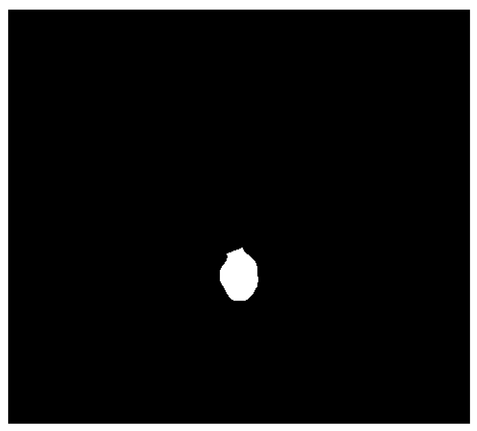
3.1.3. Droplet Cutting and Recognition

After the above image process, the position of the minimum diameter of droplet neck was found using the coordinates (XI, YI) and (XJ, YJ). The target droplet is cut off and recognized from the wire in this section.
Taking Figure 12 as the operation object, (XI, YI) and (XJ, YJ) were connected by a straight line using white pixels to seal the target droplet first. Then, pixels around the droplet connection line were set to black in order to cut off the connection between the target droplet and the wire. The processed effect and partial enlarged image are shown in Figure 17.
The target droplet was cut off and had a complete and continuous contour, which meant it has the necessary conditions to become hollow. Thus, the following step was to fill the hollow target droplet with a hole-filling algorithm. As shown in Figure 18, the hollow target droplet was filled with white pixels, whose area was the largest compared to the other white regions of the background. Therefore, the target droplet could be recognized by extracting the largest white connected domain (see Figure 19).
To sum up, for droplet cutting and recognition, the target droplet was sealed and detached by connecting (XI, YI) and (XJ, YJ), which were endpoint coordinates of the minimum distance at the neck. Above all, droplet cutting and recognition during the period with an undetached droplet can be summarized as follows:
  • Step 1: Sealing the target droplet;
  • Step 2: Detaching the target droplet;
  • Step 3: Filling hollow areas;
  • Step 4: Recognition of the target droplet.

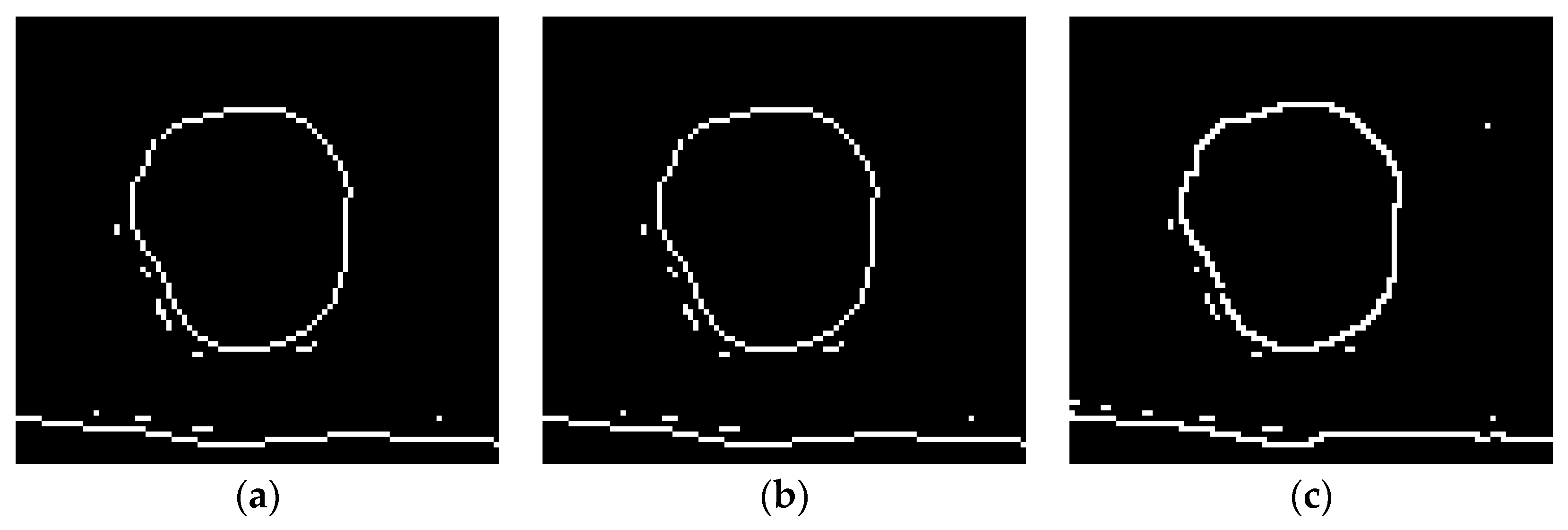
3.2. The Period with a Detached Droplet

Unlike the period with an undetached droplet, the droplet disconnects from the wire during the period with a detached droplet, as displayed in Figure 20. As a result, the process of the recognition of the droplet could be simplified, with no need to cut off the connection between the droplet and wire. Moreover, the interference of the arc was not as notable as before because of the decrease in current and arc brightness in this period. However, the first step was also to convert the color image into a grayscale image (see Figure 21).
Then, different edge operators were used to process the grayscale image directly. The edge extraction effect of the full image and the partial enlarged images near the droplet are shown in Figure 22 and Figure 23, respectively.
As displayed in Figure 22, the Sobel operator, Prewitt operator, and Roberts operator were not sensitive to background interference, and the background was relatively clean. However, some gaps could be found on the contour of droplet in Figure 23a–c. In contrast, the LoG operator and Canny operator had a strong ability to recognize edges. Although the background interference was relatively large in Figure 22d,e, it can be seen from Figure 23d,e that the droplet contour was complete and continuous.
Therefore, a hole-filling algorithm could be used on the image shown in Figure 22d,e to fill the droplet region, and the result is shown in Figure 24. It can be seen that the droplet was filled with white pixels. There were barely other white connected domains in the background in Figure 24a, while a few dispersive white connected domains can be found in Figure 24b. However, in common, these areas of the connected domains in the background were too small for the droplet. When the biggest area of connected domains was found, the droplet was also found (see Figure 25).
As a result, thanks to the relative weak intensity of the arc, there was no need to divide the droplet artificially in the images. Hence, the whole image process in the period with a detached droplet was simpler than that in the period with an undetached droplet. The LoG operator and Canny operator both showed excellent effects for recognizing the complete droplet edge. Above all, recognition of the droplet during the period with a detached droplet can be summarized as follows:
  • Step 1: Grayscale transformation;
  • Step 2: Edge operator test;
  • Step 3: Filling hollow areas;
  • Step 4: Recognition of the droplet.

4. Extraction of Droplet Kinematic Characteristics

The droplet can be approximately regarded as an object with uniform mass, such that the centroid of the droplet coincides with the center of mass. The motion state of the center of mass reflects the motion state of the whole droplet. Therefore, the centroid of the droplet can be studied to extract the kinematic characteristics of the droplet.
According to the above content, the droplet was recognized accurately as a region of white pixels in the period with an undetached droplet (see Figure 19) and the period with a detached droplet (see Figure 25), while the other parts were all black pixels. Thus, the centroid coordinates (X0, Y0) of the droplet could be calculated according to Equations (4)–(6), while f(X, Y) is the value of the pixel corresponding to the coordinates of pixel points (X, Y) in images.
f ( X , Y ) = { 1 ( when a pixel is white ) 0 ( when a pixel is black ) .
X 0 = X f ( X , Y ) f ( X , Y ) .
Y 0 = Y f ( X , Y ) f ( X , Y ) .
A series of droplet centroid coordinates can be obtained by processing a series of high-speed photographic images during the droplet transfer. If (Xi,0, Yi,0) represents the centroid coordinates of droplet at frame i, then Xi+1,0Xi,0 and Yi+1,0Yi,0 are the displacements in the X- and Y-directions of the droplet centroid from frame i to frame i + 1, respectively. However, the displacement is based on the pixel coordinates, not the real value. There is a proportional relationship between the displacement based on the pixel coordinates and the real value. The real wire diameter Dreal is known, as well as the wire diameter Dimage (in pixels) in the image. Thus, the proportional relationship K = Dreal/Dimage can be calculated. Therefore, the velocity of the droplet at frame i in the X- and Y-directions can be expressed as Equations (7) and (8), where ΔT is the time interval between the previous frame and the next frame. Moreover, total velocity can be calculated using Equation (9).
v i , X = K X i + 1 , 0 X i , 0 Δ T .
v i , Y = K Y i + 1 , 0 Y i , 0 Δ T .
v i = v i , X 2 + v i , Y 2 .
In addition, the projected area of the droplet in image Simage can be obtained. If the droplet is approximately regarded as a sphere, the diameter of the droplet in image Rimage and the real diameter of droplet R can be calculated using Equations (10) and (11), respectively. Furthermore, other relative parameters can also be calculated to study the kinematic characteristics of the droplets, such as acceleration, external force, volume, mass, momentum, kinetic energy, etc.
R image = S image π .
R = K R image .

5. Conclusions

(1) A monitoring scheme of pulsed GMAW based on a high-speed camera and laser backlight was proposed. The interference of the high-brightness arc was weakened by using a narrow band filter and ND filter. Finally, the droplet and translucent arc could both be observed clearly.
(2) An effective image-processing algorithm was proposed to extract the edge and region of the droplet. It is unable to remove the interference of the arc and obtain a high-quality image segmentation effect using only the threshold method. However, by comparison, the interference of the arc can be removed, and the droplet can be extracted precisely using the proposed image-processing method.
(3) During the period with an undetached droplet, the problem of recognizing the droplet was solved by precisely cutting the droplet at the minimum diameter of the neck. Thus, the centroid coordinates of the undetached and detached droplets could both be calculated accurately, which broadened the scope of obtaining the effective information of the droplet.
(4) Based on the proposed algorithm, a series of kinematic parameters of the droplet can be obtained, such as velocity, acceleration, size, momentum, and so on. This gives a simple and feasible method to investigate the kinematic characteristics and mathematic descriptions of the droplet flight trajectory. This paper also provides a new possible application for developing a precise automatic welding system.

Author Contributions

Methodology, P.Z.; software, P.Z. and J.W.; investigation, P.Z., T.C., and Y.T.; writing—original draft preparation, P.Z.; writing—review and editing, S.X. and P.Z.; supervision, S.X.; project administration, S.X.; funding acquisition, S.X.

Funding

This work was funded by the National Natural Science Foundation of China, grant No. 51675269 and the Priority Academic Program Development of Jiangsu Higher Education Institutions (PAPD).

Conflicts of Interest

The authors declare no conflict of interest.

References

  1. Kim, Y.S.; Eagar, T.W. Analysis of Metal Transfer in Gas Metal Arc Welding. Weld. J. 1993, 72, 269–278. [Google Scholar]
  2. Palani, P.K.; Murugan, N. Selection of parameters of pulsed current gas metal arc welding. J. Mater. Process. Technol. 2006, 172, 1–10. [Google Scholar] [CrossRef]
  3. Joseph, A.; Farson, D.; Harwig, D.; Richardson, R. Influence of GMAW-P current waveforms on heat input and weld bead shape. Sci. Technol. Weld. Join. 2013, 10, 311–318. [Google Scholar] [CrossRef]
  4. Praveen, P.; Yarlagadda, P.K.D.V.; Kang, M.J. Advancements in pulse gas metal arc welding. J. Mater. Process. Technol. 2005, 164–165, 1113–1119. [Google Scholar] [CrossRef]
  5. Wu, C.S.; Chen, M.A.; Li, S.K. Analysis of excited droplet oscillation and detachment in active control of metal transfer. Comput. Mater. Sci. 2004, 31, 147–154. [Google Scholar] [CrossRef]
  6. Ghosh, P.K.; Dorn, L.; Devakumaran, K.; Hofmann, F. Pulsed Current Gas Metal Arc Welding under Different Shielding and Pulse Parameters; Part 1: Arc Characteristics. ISIJ Int. 2009, 49, 251–260. [Google Scholar] [CrossRef]
  7. Ghosh, P.K.; Dorn, L.; Devakumaran, K.; Hofmann, F. Pulsed Current Gas Metal Arc Welding under Different Shielding and Pulse Parameters; Part 2: Behaviour of Metal Transfer. ISIJ Int. 2009, 49, 261–269. [Google Scholar] [CrossRef] [Green Version]
  8. Thamodharan, M.; Beck, H.P.; Wolf, A. Steady and pulsed direct current welding with a single converter. Weld. J. 1999, 78, 75–79. [Google Scholar]
  9. Cai, X.Y.; Lin, S.B.; Fan, C.L.; Yang, C.L.; Zhang, W.; Wang, Y.W. Molten pool behaviour and weld forming mechanism of tandem narrow gap vertical GMAW. Sci. Technol. Weld. Join. 2016, 21, 124–130. [Google Scholar] [CrossRef]
  10. Zhang, Y.; Kovacevic, R.; Li, L. Adaptive control of full penetration gas tungsten arc welding. IEEE Trans. Contr. Syst. Technol. 1996, 4, 394–403. [Google Scholar] [CrossRef]
  11. Tsai, C.; Hou, K.; Chuang, H. Fuzzy control of pulsed GTA welds by using real-time root bead image feedback. J. Mater. Process. Technol. 2006, 176, 158–167. [Google Scholar] [CrossRef]
  12. Saeed, G.; Zhang, Y.M. Mathematical formulation and simulation of specular reflection based measurement system for gas tungsten arc weld pool surface. Meas. Sci. Technol. 2003, 14, 1671–1682. [Google Scholar] [CrossRef]
  13. Fu, G.; Tian, F.; Wang, H. Studies on softening of heat-affected zone of pulsed-current GMA welded Al-Zn-Mg alloy. J. Mater. Process. Technol. 2006, 180, 216–220. [Google Scholar] [CrossRef]
  14. Wang, G.; Huang, P.G.; Zhang, Y.M. Numerical analysis of metal transfer in gas metal arc welding under modified pulsed current conditions. Metall. Mater. Trans. B 2004, 35, 857–866. [Google Scholar] [CrossRef]
  15. Ghosh, P.K.; Dorn, L.; Hübner, M.; Goyal, V.K. Arc characteristics and behaviour of metal transfer in pulsed current GMA welding of aluminium alloy. J. Mater. Process. Technol. 2007, 194, 163–175. [Google Scholar] [CrossRef]
  16. Lin, Q.; Li, X.; Simpson, S.W. Metal transfer measurements in gas metal arc welding. J. Phys. D Appl. Phys. 2001, 34, 347–353. [Google Scholar] [CrossRef]
  17. Agapiou, G.; Kasiouras, C.; Serafetinides, A.A. A detailed analysis of the MIG spectrum for the development of laser-based seam tracking sensors. Opt. Laser Technol. 1999, 31, 157–161. [Google Scholar] [CrossRef]
  18. Hecht, E. Optics, 5th ed.; Pearson: New York, NY, USA, 2017. [Google Scholar]
  19. Van der Laan, J.D.; Scrymgeour, D.A.; Kemme, S.A.; Dereniak, E.L. Detection range enhancement using circularly polarized light in scattering environments for infrared wavelengths. Appl. Opt. 2015, 54, 2266–2274. [Google Scholar] [CrossRef]
  20. Dos Santos, E.B.F.; Pistor, R.; Gerlich, A.P. Pulse profile and metal transfer in pulsed gas metal arc welding: Droplet formation, detachment and velocity. Sci. Technol. Weld. Join. 2017, 22, 627–641. [Google Scholar] [CrossRef]
  21. Otsu, N. A threshold selection method from gray-level histograms. IEEE Trans. Syst. Man Cybern. 1979, 9, 62–66. [Google Scholar] [CrossRef] [Green Version]
  22. Sobel, I. Camera Models and Machine Perception. Ph.D. Thesis, Stanford University, Stanford, CA, USA, 1970. [Google Scholar]
  23. Prewitt, J.M. Object Enhancement and Extraction; Academic Press: New York, NY, USA, 1970. [Google Scholar]
  24. Roberts, L.G. Machine Perception of Three-Dimensional Solids. In Optical and Electro-Optical Information Processing; MIT Press: Cambridge, MA, USA, 1965. [Google Scholar]
  25. Marr, D.; Hildreth, E. Theory of edge detection. Proc. R. Soc. Lond. B Biol. Sci. 1980, 207, 187–217. [Google Scholar] [PubMed]
  26. Canny, J. A computational approach to edge detection. IEEE Trans. Pattern Anal. 1986, PAMI-8, 679–698. [Google Scholar] [CrossRef]
  27. Gonzalez, R.C.; Woods, R.E. Digital Image Processing, 4th ed.; Pearson: New York, NY, USA, 2017. [Google Scholar]
  28. Soille, P. Morphological Image Analysis: Principles and Applications; Springer Science & Business Media: Berlin, Germany, 2013. [Google Scholar]
Figure 1. Schematic diagram of gas metal arc welding (GMAW) synchronous signal acquisition system.
Applsci 09 05481 g001
Figure 2. Typical pulse current waveform and contrast images under different θ of the neutral density (ND) filter: (a) pulse current waveform; (b) translucent arc; (c) transparent arc.
Applsci 09 05481 g002aApplsci 09 05481 g002b
Figure 3. A typical image in the period with an undetached droplet.
Applsci 09 05481 g003
Figure 4. Grayscale of an original image in the period with an undetached droplet.
Applsci 09 05481 g004
Figure 5. Region of interest (ROI) of a grayscale image in the period with an undetached droplet.
Applsci 09 05481 g005
Figure 6. Effect of image segmentation using (a) the method of thresholding with the intermediate gray value of the wire and background; (b) the method of adaptive thresholding.
Applsci 09 05481 g006
Figure 7. Edge recognition effects before image enhancement: (a) Sobel operator; (b) Prewitt operator; (c) Roberts operator; (d) Laplacian of Gaussian (LoG) operator; (e) Canny operator.
Applsci 09 05481 g007aApplsci 09 05481 g007b
Figure 8. Gray histogram of region of interest (ROI).
Applsci 09 05481 g008
Figure 9. Image and histogram after adaptive histogram equalization: (a) image; (b) histogram.
Applsci 09 05481 g009
Figure 10. Image and histogram after gamma transformation: (a) image; (b) histogram.
Applsci 09 05481 g010
Figure 11. Edge recognition effects after image enhancement: (a) Laplacian of Gaussian (LoG) operator; (b) Canny operator.
Applsci 09 05481 g011
Figure 12. Results of applying enhancement algorithm and Canny edge operator: (a) effect of enhancement algorithm; (b) effect of Canny edge operator.
Applsci 09 05481 g012
Figure 13. Region of interest (ROI) selection at the neck.
Applsci 09 05481 g013
Figure 14. Binary image of region of interest (ROI) after image enhancement and Canny operator recognition.
Applsci 09 05481 g014
Figure 15. Result of sealing and filling the region of the neck: (a) sealing the region of the neck; (b) filling the region of the neck.
Applsci 09 05481 g015
Figure 16. The process of edge extraction of the droplet neck: (a) finding the largest connected domain; (b) image inversion; (c) edge detection of the left background; (d) edge detection of the right background.
Applsci 09 05481 g016
Figure 17. The processed effect and partial enlarged image of cutting: (a) full image; (b) partial enlarged image.
Applsci 09 05481 g017
Figure 18. The effect of the hole-filling algorithm.
Applsci 09 05481 g018
Figure 19. The effect of recognition of the target droplet.
Applsci 09 05481 g019
Figure 20. A typical image in the period with a detached droplet.
Applsci 09 05481 g020
Figure 21. Grayscale of an original image in the period with a detached droplet.
Applsci 09 05481 g021
Figure 22. Edge recognition effects in the period with a detached droplet: (a) Sobel operator; (b) Prewitt operator; (c) Roberts operator; (d) Laplacian of Gaussian (LoG) operator; (e) Canny operator.
Applsci 09 05481 g022
Figure 23. The partial enlarged images near the droplet after edge recognition: (a) Sobel operator; (b) Prewitt operator; (c) Roberts operator; (d) Laplacian of Gaussian (LoG) operator; (e) Canny operator.
Applsci 09 05481 g023aApplsci 09 05481 g023b
Figure 24. The result of the hole-filling algorithm: (a) Laplacian of Gaussian (LoG) operator; (b) Canny operator.
Applsci 09 05481 g024
Figure 25. Recognition of the droplet: (a) Laplacian of Gaussian (LoG) operator; (b) Canny operator.
Applsci 09 05481 g025
Table 1. Welding conditions of the pulsed gas metal arc welding (GMAW).
Average Current (A)Average Voltage (V)Welding Speed (mm/s)Gas TypeFlow Rate of Gas (L/min)
11024482% Ar + 18% CO218

