Article

Detection and Imaging of Underground Objects for Distinguishing Explosives by Using a Fluxgate Sensor Array

1
Department of Electronics & Communication, Army NCO Vocational School, National Defence University, Balıkesir 10100, Turkey
2
Department of Electrical & Electronics Engineering, Faculty of Engineering, Balıkesir University, Balıkesir 10145, Turkey
*
Author to whom correspondence should be addressed.
Appl. Sci. 2019, 9(24), 5415; https://doi.org/10.3390/app9245415
Submission received: 30 October 2019 / Revised: 30 November 2019 / Accepted: 6 December 2019 / Published: 11 December 2019
(This article belongs to the Section Electrical, Electronics and Communications Engineering)

Abstract

:
Active and passive techniques are two different techniques with which to detect buried explosives. In practice, the most preferred active method works by broadcasting a signal underground. This signal may stimulate the buried explosive and cause it to explode. It is important to eliminate or minimize this drawback to ensure the safety of the detector operator. In this respect, it is important to increase the studies on the passive detection technique which is not currently used in practice. The aim of this study was to passively detect improvised explosive devices without stimulating them, and to classify underground objects as explosive or non-explosive. A fluxgate sensor array having 33 components was used for passive magnetic field measurements, and the nearest neighborhood algorithm was preferred for classifying the resulting data. In experimental studies, 33 different samples having different amounts of ferromagnetic properties were used. Successful imaging and classification were achieved for the measurements up to 20 cm below the surface of soil. Data were recorded as 32 × 25 matrices, and then they were reduced to 32 × 2 matrices having the same features. Samples having explosive properties were distinguished from other underground objects with success rates of 86% and 95% for 32 × 25 and 32 × 2 data matrices, respectively. Classification times for 32 × 25 and 32 × 2 data matrices were 42 ms and 3.62 ms, respectively. For data groups where the best results were obtained for the data matrices, frame numbers classified in one second were calculated as 23.80 and 276.2, respectively. False alarm rate achieved was 5.31%. The experimental results proved the successes of the matrices reduction and classification approach. One of the most common problems encountered in passive detecting techniques is that the sensor position affects the measurements negatively. In this paper, a solution has been proposed for this important problem.

1. Introduction

Systems being used to detect buried explosives (BE) should classify material as to whether it is an explosive or not, and give an alert to the operator. Conversely, in order to increase the speed of the system, ignorance of some data to be evaluated as an explosive can reduce reliability, and this may cause some problems which will not be compensated for. The low false alarm rate (FAR) and fast detection feature are two important parameters in BE and improvised explosive device (IED) detection systems. High computational efficiency is required in the algorithm operated for optimum FAR and fast detection features [1]. For reliable operation, the buried explosive detection (BED) system should be able to interpret as much data as possible and assist the operator in the decision-making process [2]. IEDs randomly placed underground by illegal organizations have different properties from the explosives used by armed forces for defense purposes. Traditional BED systems broadcast signals underground while scanning the IEDs. If IEDs are buried with a circuit detecting the BED system’s broadcast frequency, the presence of the BED system will cause the IED to explode. In order to prevent such situations and IEDs from detonating, the detection method has to be passive; i.e., the BED system should not broadcast a signal during its operation. Underground object detection hardware is used in military applications, civil engineering, geological sciences, location sciences, archaeological researches, health applications, biological researches, etc. The specific properties of the object to be detected are important in the selection of the BED technique. If the object to be detected is an IED, many features must be analyzed in the selection of the BED method. There are two basic BED techniques; namely, mass analysis and trace analysis [3,4]. In the trace analysis technique, the remains of the explosive molecules in the air or soil are analyzed. In the mass analysis technique, the explosive is detected visually. The mass analysis technique is preferred more often for military purposes because it is faster. Ground penetrating radar [5,6,7,8,9,10,11,12,13], electromagnetic induction [1,14,15], nuclear quadrupole resonance [4,16,17,18], acoustic seismic [1,19,20,21,22], and neutron-based measurement [23,24,25,26,27,28] are the most important methods using mass analysis technique. In all of these methods, an underground signal is broadcast and the reflected signal from the buried object is evaluated by the BED system. The measurement made in this way is an active measurement, and the broadcast signal may cause the BE or IED to explode, as previously mentioned. It is possible to detect the underground explosives with a passive measurement system without emitting a signal to the BE. BED by the magnetic anomaly (MA) method can be applied in the following two ways:
(i)
The BE is exposed to a high level, constant magnetic field, and measurements are made with magnetic field measurement sensors over it. MA is detected, and the BE is interpreted by means of the data obtained [29,30,31,32]. Since an external fixed magnetic field is applied to the BE, the measurement made in this way is named an active measurement.
(ii)
The natural magnetic field of the earth is used to detect BE. Magnetic field lines of the earth can be considered linear for short distances. When an object is placed underground, deviations occur in linear magnetic field lines. In other words, different anomalies occur in the region where the object is buried compared to the region where the object is not buried. This measurement is a passive technique, and BEs and IEDs can be detected by evaluating these anomalies [33,34,35,36,37].
In this study, the MA method was used to detect BE and IED having ferromagnetic contents with passive measurements, and a scanning system was developed to image these objects. Magnetic field scans of 33 different samples were made at different distances. A thirty-three component fluxgate sensor array was used for magnetic field measurements, and data were collected by passive measurements. The data collected were recorded in 32 × 25 dimensional matrices, and a k-nearest neighborhood (kNN) classification study was performed. The sizes of the 32 × 25 dimensional data matrices were reduced to 32 × 2, and these matrices were used for classification. Classification results obtained with 32 × 25 and 32 × 2 dimensional matrices were compared with each other. One of the most common problems encountered in passive detecting techniques is that the sensor position affects the measurements negatively. Fluxgate or anisotropic magneto resistive (AMR) sensor arrays have been integrated to three-axis motion systems in explosive and buried object detection studies with the MA method in the literature, and data have been collected. Although the sensor arrays were moved along the x, y, and z axes during the data acquisition phase, the positions of the sensors were not changed [33,34,35,36,37]. However, even if there is no MA, changing the position of the sensor creates voltage variations at the output of the sensors. In this case, it becomes difficult to determine whether the change in the sensor output is due to a buried object or a change in the sensor position (present systems get different results based on the positioning of the sensor). In this paper, a solution is presented with circuit designed for this important problem.

2. System Design

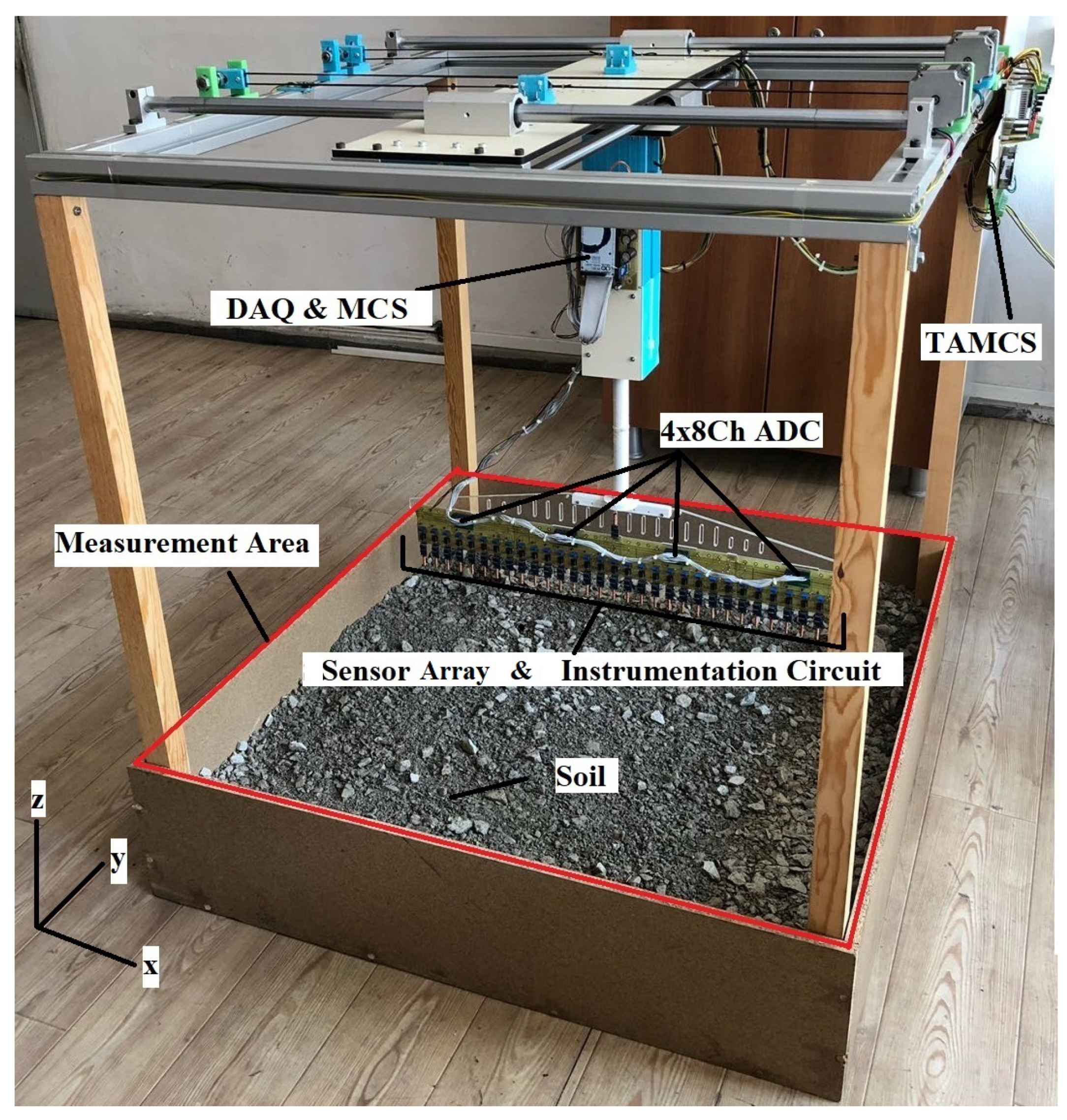
The experimental system consists of a sensor array and instrumentation circuit (SA and IC), an analogue to digital converter (ADC), a three axis motion control system (TAMCS), data acquisition and main control systems (DAQ and MCS), and a graphical user interface unit (GUIU). In the Figure 1 and Figure 2, the basic diagram and the appearance of the BED system are shown, respectively.
A fluxgate sensor named TE100 (Figure 3) is preferred for magnetic field measurements in SA and IC system design. The TE100 fluxgate sensor contains appropriate parameters for measuring the earth’s natural magnetic field strength. The natural magnetic field strength anywhere on the earth is between 25 and 65 micro Tesla ( μ T), and the measurement range of TE100 is ±100 μ T. It generates differential voltage from 1.5 V to 3.5 V depending on the magnitude of applied magnetic field. This voltage range is ideal for working with microcontrollers or microprocessors. TE100 also has specifications of % ±0.3 μ T accuracy, <2 nT/K zero shift, and 0 to 1 kHz (−3 dB) bandwidth. It is possible to change the differential voltage of the TE100 output (+) and output (−) pins in two ways.
(i)
Changing the magnetic field strength and field line angles around a fixed positioned TE100.
(ii)
Moving the TE100 at different angles according to constant magnetic field lines.
If it is assumed that the designed passive measurement system is moved on a land surface, so it is understood that it will not be possible to keep the direction of TE100s constant, and therefore output voltages of the sensors will change continuously depending on their direction. It is difficult to determine whether these changes are due to a buried object-dependent anomaly or a change in the position. Therefore, these changes, which are a function of the TE100 position, and which have noise characteristics must be removed or minimized. In this study, a measuring circuit was developed to minimize the noise caused by TE100’s position and to detect magnetic anomalies that only the buried object generates.
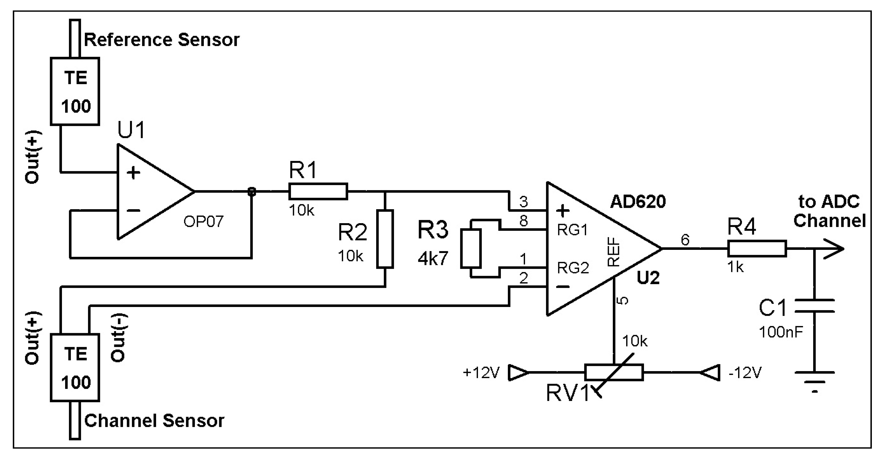
Figure 4 and Figure 5 show the basic diagram and the circuit schematic of the instrumentation circuit we designed, respectively. It is known that the vectoral sum of the magnitudes of two magnetic fields in the same axis but in different directions is zero. With this information, an aim was to produce 0 V in total for two TE100s placed in the same axis but in different directions. Using the circuit in Figure 5 for each sensor, a sensor array consisting 33 pieces of TE100 was formed as shown in Figure 4. Thus, using this sensor array, the BED system, shown in Figure 1, was designed. All these sensors are in the same measurement axis, but only one TE100, to be used for reference sensor (Sref), is in the opposite direction. In the absence of magnetic anomalies, the output of all TE100 channels is equal to 0 V. In the case of magnetic anomalies, the output voltages of TE100 channels change according to the magnitude and intensity of the anomalies. Deviations in the voltages of the channels are due to the MA and contain data about the buried object.
Two magnetic field sensors were placed in the same line with opposite directions in order to produce voltages equal in magnitude but opposite in sign. As shown in Figure 5, the output signal of the reference sensor is common for the 32 channel sensor array. In order to distribute this signal to all channels without attenuation and noise, buffer amplifiers with a gain of 1 were preferred at the channel inputs. Voltages of the buffer amplifier output and the OUT (+) output of the channel sensor are added with each other by the resistors R1 and R2. The resistance values of R1 and R2 are equal. Thus, a signal which is the half of the signal obtained by adding the OUT (+) outputs of the reference and channel sensor arrives at the (+) input of the instrumentation amplifier. As a result of this, the unwanted signal component arising from the Earth’s magnetic field in the signal is removed. Thus, a voltage of 1 V for 50 μ T is obtained regardless of the position of the sensor. However, this voltage is produced on a reference of 2.5 V. A differential amplification operation is performed in the instrumentation amplifier to remove the effect of this reference voltage. At the OUT (−) output of the channel sensor, there is a reference voltage of 2.5 V. The difference signal between the signal reaching the (+) input terminal of the instrumentation and 2.5 V obtained from OUT (−) output of the channel sensor is amplified. This signal is then passed through the first order, passive-low pass filter consisting of R3-C1 elements and directed to the relevant ADC channel [38].
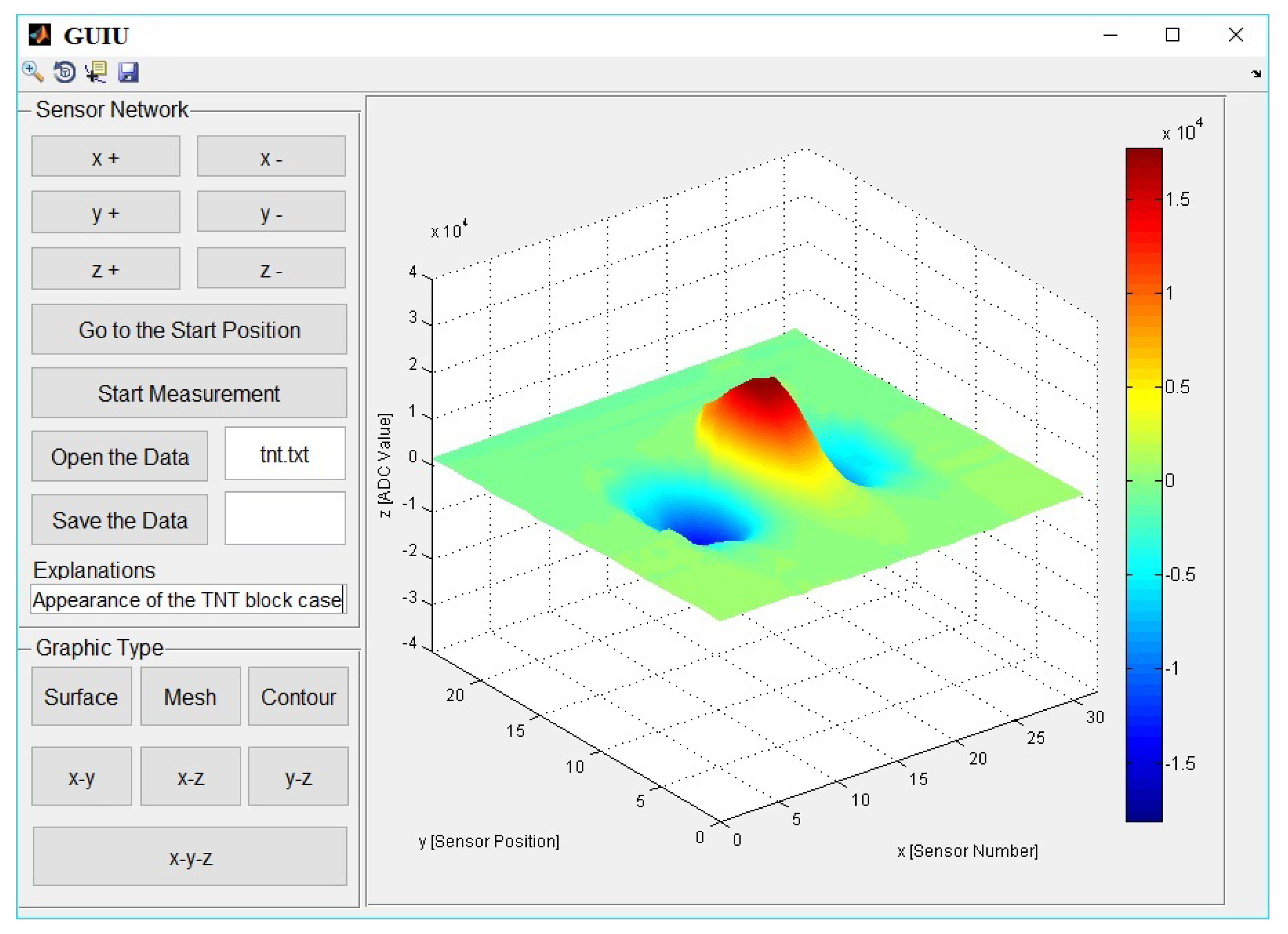
The ADC module is used to digitize the analogue voltages obtained from the instrumentation circuit. This module transfers digitized data to the DAQ and MCS. A 32-channel ADC network was constructed using four ADC modules each having eight channels, and this network is controlled by the DAQ and MCS. The TAMCS is a system designed to obtain data from the magnetic behavior of the BE by moving the designed sensor array over the soil covering measurement area. DAQ and MCS, together are a system that establishes communication between GUIU, SA and IC, and TAMCS. Through DAQ and MCS, the commands from the computer are transferred to TAMCS, and the data obtained from the SA and IC are transferred to the computer during magnetic field scans. A graphical user interface (GUI) was designed for recording the magnetic field data in a certain format in the classification stage, for sending the commands to control TAMCS, for starting/finishing BE scans, and analyzing the graphics. The GUIU was developed using Matlab GUI. A screen appearance of the GUIU is shown in Figure 6. The data collected in the GUIU were recorded in "txt" format, and have been used as an example dataset for the classification.

3. Pattern Recognition of Magnetic Field Data

Pattern recognition consists of two basic stages: feature extraction and classification.

3.1. Feature Extraction

In this phase; the size of the magnetic field data was reduced, descriptive properties were determined, and normalization was applied. The feature extraction phase plays the most important role in the system’s performance. In this study, the following features related to datasets were extracted.
*
Maximum (Max): The element which has the greatest value in the dataset.
*
Minimum (Min): The element which has the smallest value in the dataset.
*
Standard deviation ( σ ): Criterion that is used to quantify the amount of dispersion of a dataset. It is calculated by Equation (1).
σ = i = 1 n x i - μ 2 n .
In the Equation (1), xi is element “i” in the dataset, μ is the mean value of the dataset, and n is number of elemets in dataset.
*
The Kurtosis Coefficient (KC): The sharpness of the peak of a frequency-distribution curve. It is calculated by Equation (2).
K C = i = 1 n x i - μ 4 n σ 4 .
*
The arithmetic mean (AM): The arithmetic mean of the numeric values in the dataset.

3.2. Classification Algorithm

kNN classification algorithm is preferred to classify explosive and non-explosive materials. In the literature, it is clear that explosives can be detected by a kNN classification algorithm and significant results have been obtained [37,39].
kNN is a simple and widely used classification method [40]. kNN is a non-parametric approach that was widely applied to statistics in the early 1970s [41,42,43]. kNN is regarded as one of the top 10 algorithms in data mining, due to its simplicity, effectiveness, and implementation [41,44]. The kNN-based classification technique can be effectively applied in real world and practical classification tasks in several fields, such as expert and intelligence systems [41]. The kNN algorithm is divided into two phases: the training phase and the classification phase [45]. The training examples are vectors in the multidimensional feature space. Each vector has a class label. The training phase of the algorithm only stores the feature vector (reference vector library) and class label of the training samples [45]. In the classification phase, k is a user-defined constant, and an unlabeled vector is classified by assigning the label which is most frequent among the k training samples nearest to that query point. In other words, the kNN method compares the query point or an input feature vector with a library of reference vectors, and the query point is identified to be of the class of library feature vectors to which it has the closest distance [45]. Several distance criteria have been used in previous studies, such as the Euclidean distance, correlation between samples, city block distance, cosine distance, and Hamming distance [46]. In this study, Euclidean distance criteria were used. which can be formulated as Equation (3).
d i s t ( x i , x j ) = d = 1 D ( x i , d - x j , d ) 2 ,
where dist(x i , x j ) represents the Euclidean distance between two data points x i and xj, and samples are represented by d feature dimensions [46].
Success rate is one of the most important parameters giving information about whether the classifier is working effectively. Another parameter that is used to evaluate the success of the classifier is the reliability coefficient ( κ ), and it is described as the criterion used for giving the same result every time for the data being classified [47]. κ can be formulated as in Equation (4) [48].
κ = π A - π E 1 - π E .
π A and π E can be formulated as in Equations (5) and (6), respectively.
π A = T P + T N T P + T N + F P + F N
π E = ( T P + F P ) . ( T P + F N ) ( T P + T N + F P + F N ) 2 + ( F N + T N ) . ( F P + T N ) ( T P + T N + F P + F N ) 2 .
In the Equations (5) and (6), TP, FP, TN, and FN are the predicted true positive, false positive, true negative, and false negative values, respectively.
The basic success criteria and parameters of a classification or test are accuracy (ACC), sensitivity (SNS), specificity (SPC), positive/negative predictive values, and positive/negative likelihood ratios [47,49]. ACC, SNS, and SPC can be formulated as Equations (7)–(8), respectively.
A C C = T P + T N T P + T N + F P + F N
S N S = T P T P + F N
S P C = T N T N + F P .
FAR is an expression of performance used for misclassification of explosive detection. FAR can be formulated as Equation (9) [47].
F A R = F P + F N T P + T N + F P + F N .

4. Experiments

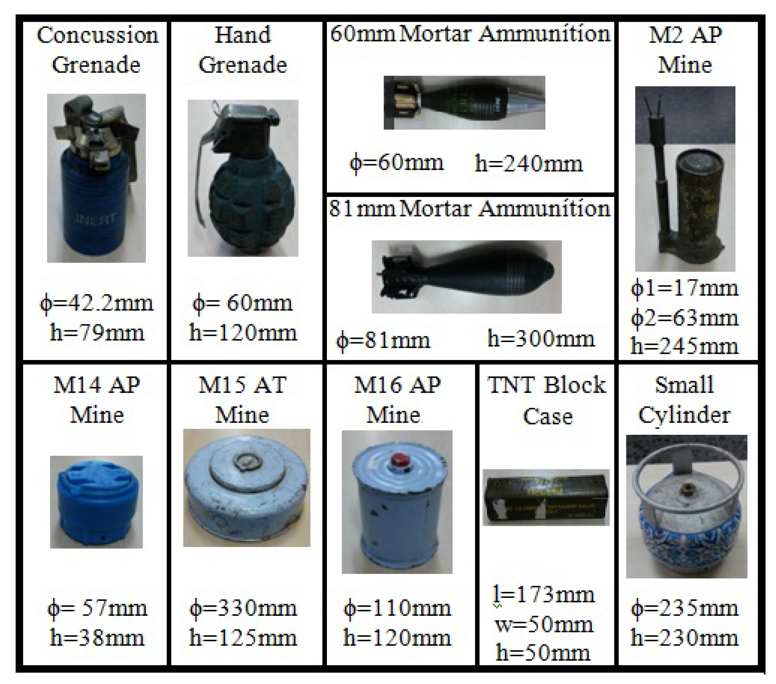
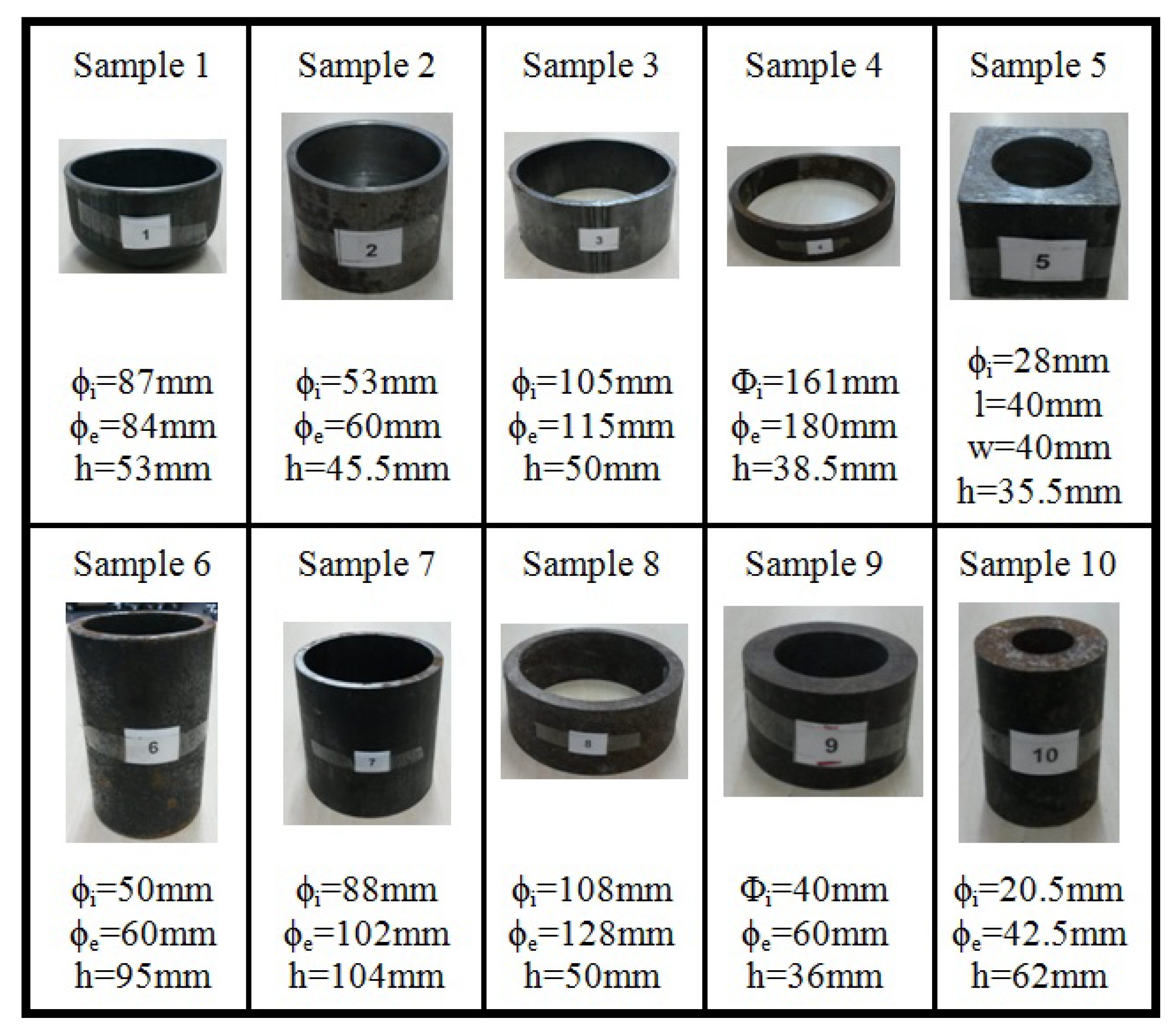
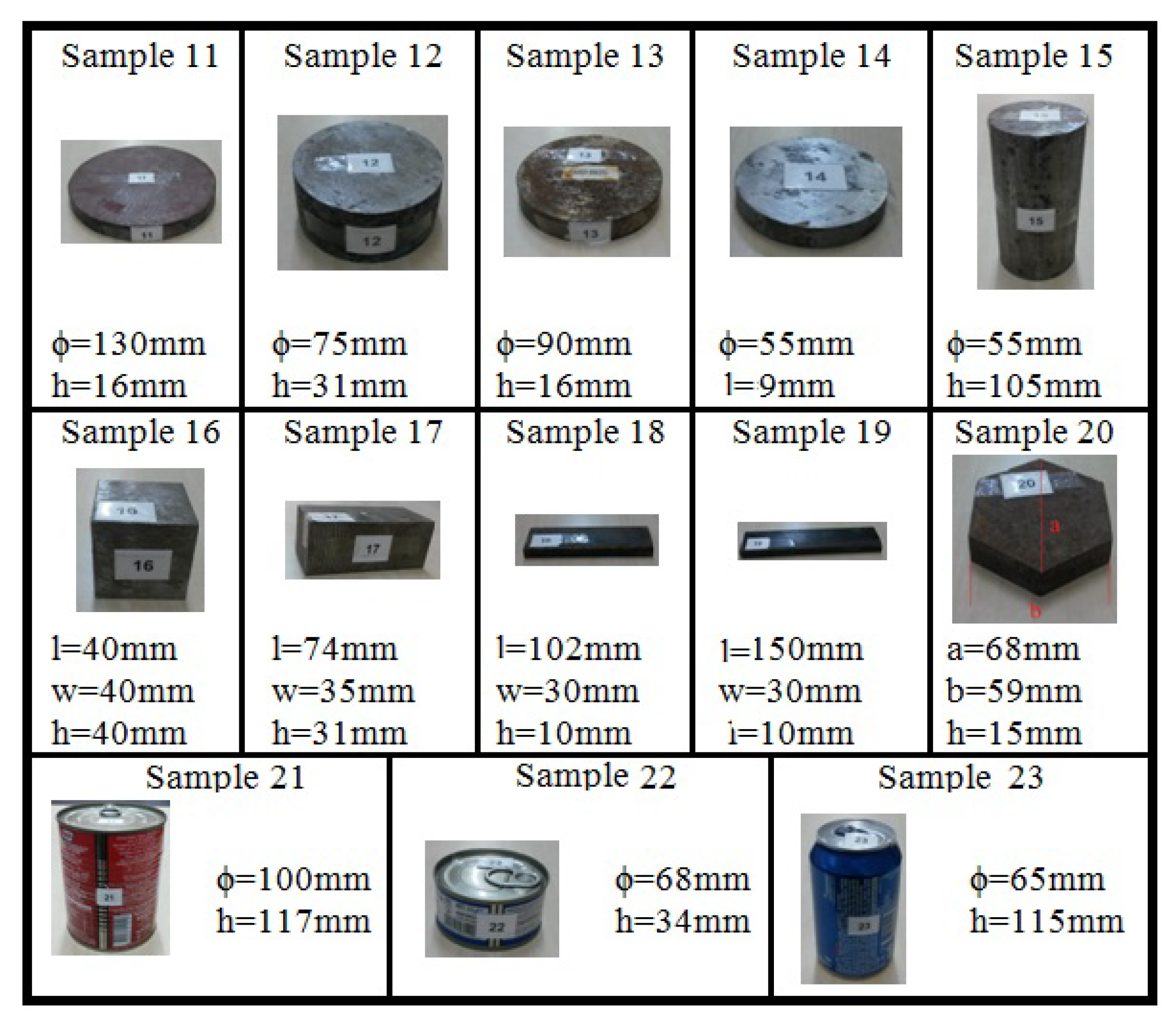
With the aim of detecting and classifying BEs and IEDs by the designed data collection system, the area used for the measurements was first filled with humid soil. A test sample was buried 2–3 cm under the top of the soil surface, and its position was kept constant. The sensor array was placed along the positive x-axis direction, and then data collection process was carried out by moving this sensor array along the y-axis in 25 steps. Each buried test sample was scanned along the positive z-axis at distances of 5 cm, 10 cm, 15 cm, and 20 cm from the top of the buried sample. And then the 32 × 25 dimensions data matrices were obtained from each scan (32: Number of sensors placed along the x axis, 25: Number of scan steps of y axis). In the study, 33 different samples having different ferromagnetic properties were scanned. Ten out of thirty-three samples were explosives in standard production, and they have frequently been used for IEDs and warfare. The appearances and general physical properties of these samples are shown in Figure 7. In addition, ten out of thirty-three samples were kinds of cases having different sizes and geometries and are still being used in the IED productions. The appearances and general physical properties of these samples are given in Figure 8. The remaining 13 samples were non-explosive materials having IED geometries and yielding close results to the magnetic field images of IEDs and explosives. The appearances and general physical properties of these samples are given in Figure 9.
A two-dimensional gray scale image of each sample was obtained by using GUIU with the help of data matrices of 32 × 25 dimensions recovered from the scan results. Two-dimensional gray scale images scanned at 5cm distance for all 33 samples are given in Figure 10. As can be seen in the Figure 10, light regions indicate positive magnetic field density, whereas dark regions indicate negative magnetic field density.
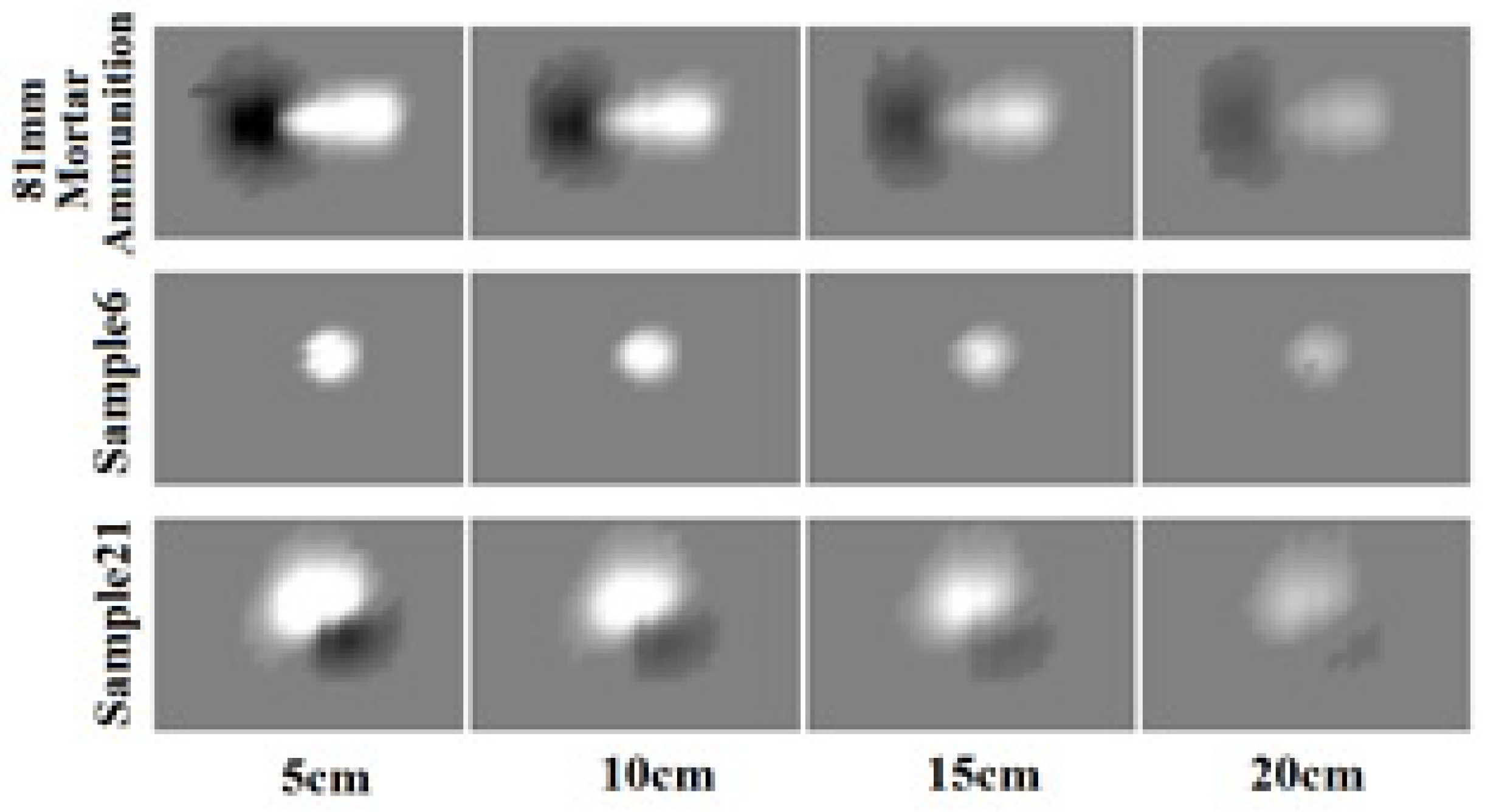
In gray scale images, the color information is stored in numerical values between 32,768 (100% white) and −32,768 (100% black) obtained from the ADC channels. The zero (gray) value indicates the combination of 50% black and 50% white and this corresponds to no magnetic field. As can be seen in Figure 11, the numbers of gray points in the images increase with the increase of scanning height in the z-axis for all samples. When the images obtained from different heights are evaluated as a whole, it can be seen that rate of the gray scale in the images does not change too much. In total, 132 different datasets were recorded as a result of the magnetic measurements carried out at 5 cm, 10 cm, 15 cm, and 20 cm distances for 33 different test samples. Each dataset actually contains a 32 × 25-dimensional data matrix. In the classification study, 80 datasets were categorized as explosives/IEDs, and the other 52 datasets as non-explosive materials. Max, Min, σ , KC, and AM features were calculated and used to characterize these datasets. It is important to know which features will be used in the classification. The usage of single feature is more likely to cause coincidence results in the classification. Eleven different groups were created to examine the effects of the all features for the classification. The feature groups and elements are given in Table 1.

5. Results and Discussion

Within the scope of two different classification studies, TP, FP, TN, FN, ACC, SNS, SPC, and κ values were calculated, and different k values were selected. In the first classification study, 32 × 25 datasets were used, and the kNN classification algorithms were operated for the feature groups in Table 1 and for different k values. And then, TP, FP, TN, FN, ACC, and κ values were calculated using the numerical values obtained. The results of the first classification process are given in Table 2. The conditions for the κ being greater than 0.6 correspond to the "good reliability" for the chosen conditions in the classification [50]. When the classification results are examined, it can be easily seen that the best ACC value was obtained in the Group 11 while k = 3 .
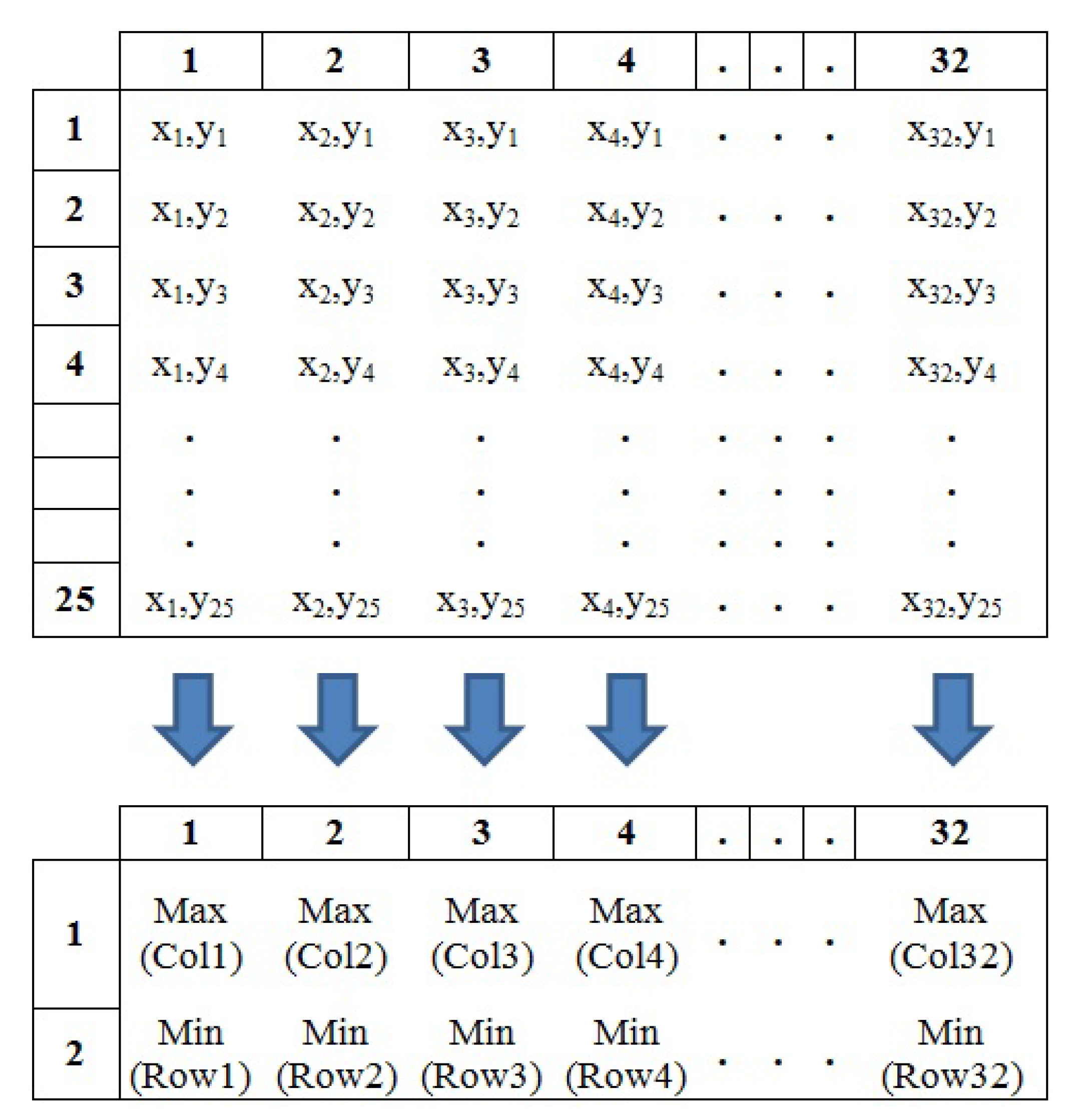
During the sample scan, x–z projection plots were also obtained. Figure 12 shows the x–z projection plots of 60 mm Mortar Ammunition, M16AP (Anti-Personnel) Mine, Sample 3, and Sample 11 scanned at 5 cm distance. These plots includes different unique properties for each sample. Therefore, instead of using 32 × 25 data matrices directly, it was thought that the use of data matrices obtained from x–z projection plots would provide significant improvements in system and classification performance. For this purpose, new 32 × 2 data matrices having same properties were created by reducing the dimensions of 32 × 25 data matrices. Thus, 32 × 25 matrices, which had800 independent data points, were reduced into 32 × 2 matrices, which had 64 independent data points. While generating 32 × 2 data matrices, the maximum and minimum values for each column of 32 × 25 data matrices were determined. Then, the maximum and minimum values of each 32 × 25 matrix were placed in the first and second rows of 32 × 2 data matrices, respectively. A schematic diagram of how these processes were performed is given in Figure 13.
In the second classification study, 32 × 2 datasets were used, and the kNN classification algorithms were operated for the feature groups in Table 1 and for different k values. And then, TP, FP, TN, FN, ACC, and κ values were calculated using the numerical values obtained. The results of the second classification process are given in Table 3. The conditions for the κ being greater than 0.6 correspond to the "good reliability" for the chosen conditions in the classification. When the classification results are examined, it can be easily seen that the best ACC value was obtained in the Group 10 while k = 3 . In this study, explosive materials have been successfully distinguished from non-explosive ones by using reduced data matrices and the features that have been defined. The best result has been obtained for the comparison based on the standard deviation and arithmetic mean. While the best ACC value has been achieved to be 0.86 for the classification carried out with 32 × 25 data matrices, a 0.95 ACC value has been obtained for 32 × 2. In the classifications made with 32 × 25 data matrices, the κ value was obtained as greater than 0.6 for 7 conditions; this value was obtained for 27 conditions in 32 × 2 data matrices. Both of those results reveal a significant increase in classification success after reducing the matrix dimensions. If there is a comparison made between in the mean values of TP, FP, TN, FN, ACC, and κ , then the best results have been obtained for 32 × 2 data matrices. This situation explains that the dimension reduction is essential to get best kNN classification. Classification times have been determined to be 42 ms and 3.62 ms for the groups with the best results: the data matrices of 32 × 25 and 32 × 2, respectively. This means that 23.80 and 276.2 datasets can be classified in one second for 32 × 25 and 32 × 2 data matrices, respectively. By subjecting 32 × 25 and 32 × 2 data matrices to the kNN classification algorithm, samples having explosive properties have been distinguished successfully from the non-explosives materials by 86% and 95%, respectively. There have been significant improvements in the speed and in the number of datasets processed in one second in the classification made for 32 × 2 data matrices. In the conventional buried object and explosive detection systems, FAR is 50% (50% classification success). In our study, FAR was calculated as 5.31% for selected samples, and this ratio indicates a significant improvement.

6. Conclusions

The results which were obtained with this study have been compared with the similar ones in the literature.
*
Yılmaz et al. performed passive measurements in their studies, used the MA method, and classified five different types of mines at 85.8% [37]. In our novel study, 10 different types of explosives were classified with 95% performance.
*
In the study of Nazlıbilek et al., active measurements were made the MA method was used, and the explosives were detected and visualized [29]. In our study, passive measurements were made, explosives were detected, and real time imaging was performed.
*
Ege et al. used a fluxgate sensor network in their study and reported that buried bodies having ferromagnetic content could be detected by passive measurements [33]. However, the position of the sensor network affected the results negatively. In our study, independent measurements without being effected by position were made with fluxgate sensors.
*
In the previous studies [29,33,37] the measurement results changed depending on the sensor position, which made it difficult to make real-time measurements. By the measuring circuit developed in our study, position-independent measurements can be performed.
Studies conducted with magnetic anomaly method for detection buried objects and explosives have still been continueing. There are still many unknowns for the usage of this method in real-time measurements. It is thought that the studies to be conducted with different soil types, different geographical regions, and different classification methods will determine the future in this field.

Author Contributions

Conceptualization, S.G. and S.D.; system design, S.G. and M.K.; methodology, S.G., M.K. and S.D.; software, S.G. and M.K.; validation, S.G. and S.D.; supervision, S.G. and M.K.; writing, original draft, S.G. and M.K.; writing, review and editing, S.G., M.K. and S.D. All authors approved the final version.

Funding

This research received no external funding.

Acknowledgments

This study was supported by the Balıkesir University Research Fund (project number 2016/103). S. Doğan and S. Gürkan would like to thank to Turkish Academy of Sciences (TUBA) for partial support.

Conflicts of Interest

The authors declare no conflict of interest.

References

  1. Ege, Y.; Kakilli, A.; Kılıç, O.; Calik, H.; Citak, H.; Nazlibilek, S.; Kalender, O. Performance Analysis of Techniques Used for Determining Land Mines. Int. J. Geosci. 2014, 5, 1163–1189. [Google Scholar] [CrossRef] [Green Version]
  2. Hussein, E.; Waller, E. Landmine detection: The problem and the challenge. Appl. Radiat. Isot. 2000, 53, 557–563. [Google Scholar] [CrossRef]
  3. Fatah, A.; Arcilesi, R.; Clindock, J. Guide for the Selection of Explosives Detection and Blast Mitigation Equipment for Emergency First Responders; Preparedness Directorate Office of Grants and Training: Washington, WA, USA, 2008. [Google Scholar]
  4. Baysoy, D. Numerical Evaluation of a Mine Detection System Based on Nuclear Techniques. Ph.D. Thesis, Yıldız Technical University, İstanbul, Turkey, 2010. [Google Scholar]
  5. Gonzalez-Huici, M.A.; Giovanneschi, F. A combined strategy for landmine detection and identification using synthetic GPR responses. J. Appl. Geophys. 2013, 99, 154–165. [Google Scholar] [CrossRef]
  6. Hoarau, Q.; Ginolhac, G.; Atto, A.M.; Nicolas, J.M.; Ovarlez, J.P. Robust adaptive detection of buried pipes using GPR. In Proceedings of the 2016 24th European Signal Processing Conference (EUSIPCO), Budapest, Hungary, 29 August–2 September 2016; pp. 533–537. [Google Scholar] [CrossRef] [Green Version]
  7. van der Merwe, A.; Gupta, I.J. A novel signal processing technique for clutter reduction in GPR measurements of small, shallow land mines. IEEE Trans. Geosci. Remote Sens. 2000, 38, 2627–2637. [Google Scholar] [CrossRef] [Green Version]
  8. Chan, L.; Peters, L.; Moffatt, D. Improved performance of a subsurface radar target identification system through antenna design. IEEE Trans. Antennas Propag. 1981, 29, 307–311. [Google Scholar] [CrossRef]
  9. Kolba, M.P.; Jouny, I.I. Buried land mine detection using complex natural resonances on GPR data. In Proceedings of the IEEE International Geoscience and Remote Sensing Symposium, Toulouse, France, 21–25 July 2003; Volume 2, pp. 761–763. [Google Scholar] [CrossRef]
  10. Dumanian, A.J.; Rappaport, C.M. Enhanced detection and classification of buried mines with an UWB multistatic GPR. In Proceedings of the 2005 IEEE Antennas and Propagation Society International Symposium, Washington, DC, USA, 3–8 July 2005; Volume 3B, pp. 88–91. [Google Scholar] [CrossRef]
  11. Mohana, M.A.; Abbas, A.M.; Gomaa, M.L.; Ebrahim, S.M. Discrimination between landmine and mine-like targets using wavelets and spectral analysis. NRIAG J. Astron. Geophys. 2013, 2, 54–66. [Google Scholar] [CrossRef] [Green Version]
  12. Missaoui, O.; Frigui, H.; Gader, P. Land-Mine Detection With Ground-Penetrating Radar Using Multistream Discrete Hidden Markov Models. IEEE Trans. Geosci. Remote Sens. 2011, 49, 2080–2099. [Google Scholar] [CrossRef]
  13. Montoya, T.P.; Smith, G.S. Land mine detection using a ground-penetrating radar based on resistively loaded Vee dipoles. IEEE Trans. Antennas Propag. 1999, 47, 1795–1806. [Google Scholar] [CrossRef]
  14. Ramachandran, G.; Gader, P.D.; Wilson, J.N. GRANMA: Gradient Angle Model Algorithm on Wideband EMI Data for Land-Mine Detection. IEEE Geosci. Remote. Sens Lett. 2010, 7, 535–539. [Google Scholar] [CrossRef]
  15. Xiao, W.; Yi, X.; Pan, F.; Li, R.; Xia, T. Chapter 2—Acoustic, Electromagnetic and Optical Sensing and Monitoring Methods. In Underground Sensing; Pamukcu, S., Cheng, L., Eds.; Academic Press: Cambridge, MA, USA, 2018; pp. 43–139. [Google Scholar] [CrossRef]
  16. Ostafin, M.; Nogaj, B. 14N-NQR based device for detection of explosives in landmines. Measurement 2007, 40, 43–54. [Google Scholar] [CrossRef]
  17. Blauch, A.; Schiano, J.; Ginsberg, M. Landmine detection using feedback NQR. Proc. SPIE 1999, 3710, 1–4. [Google Scholar] [CrossRef]
  18. Deas, R.; Cervantes, C.; Schaedel, S. Landmine Detection by Nuclear Quadrupole Resonance(NQR); US Army RDECOM CERDEC Night Vision and Electronic Sensors Directorate Fort Belvoir: Fort Belvoir, VA, USA, 2004; pp. 1–5. [Google Scholar]
  19. Akseli, I.; Mani, G.N.; Cetinkaya, C. Non-destructive acoustic defect detection in drug tablets. Int. J. Pharm. 2008, 360, 65–76. [Google Scholar] [CrossRef] [PubMed]
  20. Behboodian, A.; Scott, W.R.; McClellan, J.H. Signal processing of elastic surface waves for localizing buried land mines. In Proceedings of the Conference Record of the Thirty-Third Asilomar Conference on Signals, Systems, and Computers (Cat. No.CH37020), Grove, CA, USA, 24–27 October 1999; Volume 2, pp. 827–830. [Google Scholar] [CrossRef]
  21. Zeng, Y.Q.; Liu, Q.H. Acoustic detection of buried objects in 3-D fluid saturated porous media: Numerical modeling. IEEE Trans. Geosci. Remote Sens. 2001, 39, 1165–1173. [Google Scholar] [CrossRef]
  22. Chu, P.C.; Cornelius, M.; Wegstaff, M. Effect of Suspended Sediment on Acoustic Detection Using the Navy’s CASS-GRAB Model. In Proceedings of the OCEANS 2005 MTS/IEEE, Washington, DC, USA, 19–23 September 2005; pp. 1–7. [Google Scholar] [CrossRef]
  23. Baysoy, D.; Subaşı, M. Landmine Detection with the Neutron-Induced. In Proceedings of the X National Congress of Nuclear Science and Technologies Congress, Muğla, Türkiye, 6–9 October 2009; pp. 61–69. [Google Scholar]
  24. Elsheikh, N.A. Multi-parameter optimization of a (3He-252Cf-3He) neutron backscattering sensor for landmine detection. J. Radiat. Res. Appl. Sci. 2017, 10, 122–127. [Google Scholar] [CrossRef]
  25. Bom, V.R.; Datema, C.P.; van Eijk, C.W.E. DUNBLAD, the Delft University Neutron Backscatter LAnd-mine Detector, a status report. AIP Conf. Proc. 2003, 680, 935–938. [Google Scholar] [CrossRef]
  26. Kabessa, Y.; Eyal, O.; Bar-On, O.; Korouma, V.; Yagur-Kroll, S.; Belkin, S.; Agranat, A.J. Standoff detection of explosives and buried landmines using fluorescent bacterial sensor cells. Biosens. Bioelectron. 2016, 79, 784–788. [Google Scholar] [CrossRef]
  27. Miri-Hakimabad, H.; Panjeh, H.; Vejdani-Noghreiyan, A. Experimental optimization of a landmine detection facility using PGNAA method. Nucl. Sci. Tech. 2008, 19, 109–112. [Google Scholar] [CrossRef]
  28. Csikai, J.; Dóczi, R.; Király, B. Investigations on landmine detection by neutron-based techniques. Appl. Radiat. Isot. 2004, 61, 11–20. [Google Scholar] [CrossRef]
  29. Nazlibilek, S.; Kalender, O.; Ege, Y. Mine Identification and Classification by Mobile Sensor Network Using Magnetic Anomaly. IEEE Trans. Instrum. Meas. 2011, 60, 1028–1036. [Google Scholar] [CrossRef]
  30. Ege, Y.; Kalender, O.; Nazlibilek, S. Direction finding of moving ferromagnetic objects inside water by magnetic anomaly. Sens. Actuators A Phys. 2008, 147, 52–59. [Google Scholar] [CrossRef]
  31. Nazlibilek, S.; Ege, Y.; Kalender, O. A multi-sensor network for direction finding of moving ferromagnetic objects inside water by magnetic anomaly. Measurement 2009, 42, 1402–1416. [Google Scholar] [CrossRef]
  32. Söyler, S.; Kurt, E.; Dağ, O. Optimization of the Magnetic Anomaly Signals from a New Land Mine Detection Device. In Proceedings of the 11th International Conference on Applications of Electrical and Computer Engineering, Athens, Greece, 7–9 March 2012; pp. 178–183. [Google Scholar]
  33. Ege, Y.; Çoramık, M.; Kabadayı, M.; Çıtak, H.; Kalender, O.; Yürüklü, E.; Kurt, U.; Nazlıbilek, S. Anomaly detection with low magnetic flux: A fluxgate sensor network application. Measurement 2016, 81, 43–56. [Google Scholar] [CrossRef]
  34. Nazlibilek, S.; Ege, Y.; Kalender, O.; Sensoy, M.G.; Karacor, D.; Sazlı, M.H. Identification of materials with magnetic characteristics by neural networks. Measurement 2012, 45, 734–744. [Google Scholar] [CrossRef]
  35. Ege, Y.; Sensoy, M.G.; Kalender, O.; Nazlibilek, S. Numerical Analysis for Remote Identification of Materials With Magnetic Characteristics. IEEE Trans. Instrum. Meas. 2011, 60, 3140–3152. [Google Scholar] [CrossRef] [Green Version]
  36. Jordanova, N. Applications of Soil Magnetism; Elseiver: Amsterdam, The Netherlands, 2017. [Google Scholar]
  37. Yilmaz, C.; Kahraman, H.T.; Söyler, S. Passive Mine Detection and Classification Method Based on Hybrid Model. IEEE Access 2018, 6, 47870–47888. [Google Scholar] [CrossRef]
  38. Gürkan, S.; Karapınar, M.; Doğan, S. Design of a data acquisition system for passive detection of buried explosives. In Proceedings of the 4th International Conference on Electrical and Electronic Engineering (ICEEE), Ankara, Turkey, 8–10 April 2017; pp. 338–341. [Google Scholar]
  39. Silva, J.S.; Guerra, I.F.L.; Bioucas-Dias, J.; Gasche, T. Landmine Detection Using Multispectral Images. IEEE Sens. J. 2019, 19, 9341–9351. [Google Scholar] [CrossRef]
  40. Jiang, Z.; Ni, F.; Yang, D.; Li, C.; Yang, F.; Liu, H. A Hybrid Mapping Method with Position and Stiffness for Manipulator Teleoperation. Appl. Sci. 2019, 9, 5005. [Google Scholar] [CrossRef] [Green Version]
  41. Xu, H.; Zhou, J.; Asteris, P.G.; Jahed Armaghani, D.; Tahir, M.M. Supervised Machine Learning Techniques to the Prediction of Tunnel Boring Machine Penetration Rate. Appl. Sci. 2019, 9, 3715. [Google Scholar] [CrossRef] [Green Version]
  42. Dudaa, R.; Hart, P.E. Pattern Classification and Scene Analysis; Wiley: Hoboken, NJ, USA, 1973. [Google Scholar]
  43. Franco-Lopez, H.; Ek, A.; Bauer, M. Estimation and mapping of forest stand density, volume, and cover type using the k-nearest neighbors method. Remote. Sens. Environ. 2001, 77, 251–274. [Google Scholar] [CrossRef]
  44. Wu, X.; Kumar, V.; Ross Quinlan, J.; Ghosh, J.; Yang, Q. Top 10 algorithms in data mining. Knowl. Inf. Syst. 2008, 14, 1–37. [Google Scholar] [CrossRef] [Green Version]
  45. Shi, C.T. Signal Pattern Recognition Based on Fractal Features and Machine Learning. Appl. Sci. 2018, 8, 1327. [Google Scholar] [CrossRef] [Green Version]
  46. Islam, M.R.; Kim, Y.H.; Kim, J.Y.; Kim, J.M. Detecting and Learning Unknown Fault States by Automatically Finding the Optimal Number of Clusters for Online Bearing Fault Diagnosis. Appl. Sci. 2019, 9, 2326. [Google Scholar] [CrossRef] [Green Version]
  47. Baratloo, A.; Hosseini, M.; Negida, A.; Ashal, G.E. Part 1: Simple Definition and Calculation of Accuracy, Sensitivity and Specificity. Emergency 2015, 3, 48–49. [Google Scholar] [PubMed]
  48. Weka 3: Machine Learning Software in Java. 2019. Available online: https://www.cs.waikato.ac.nz/ml/weka/index.html (accessed on 10 November 2019).
  49. Altman, D.G.; Bland, J.M. Statistics Notes: Diagnostic tests 1: Sensitivity and specificity. BMJ 1994, 308, 1552. [Google Scholar] [CrossRef] [Green Version]
  50. McHugh, M. Interrater reliability: The kappa statistic. J. Croat. Soc. Med. Biochem. Lab. Med. 2002, 22, 276–282. [Google Scholar] [CrossRef]
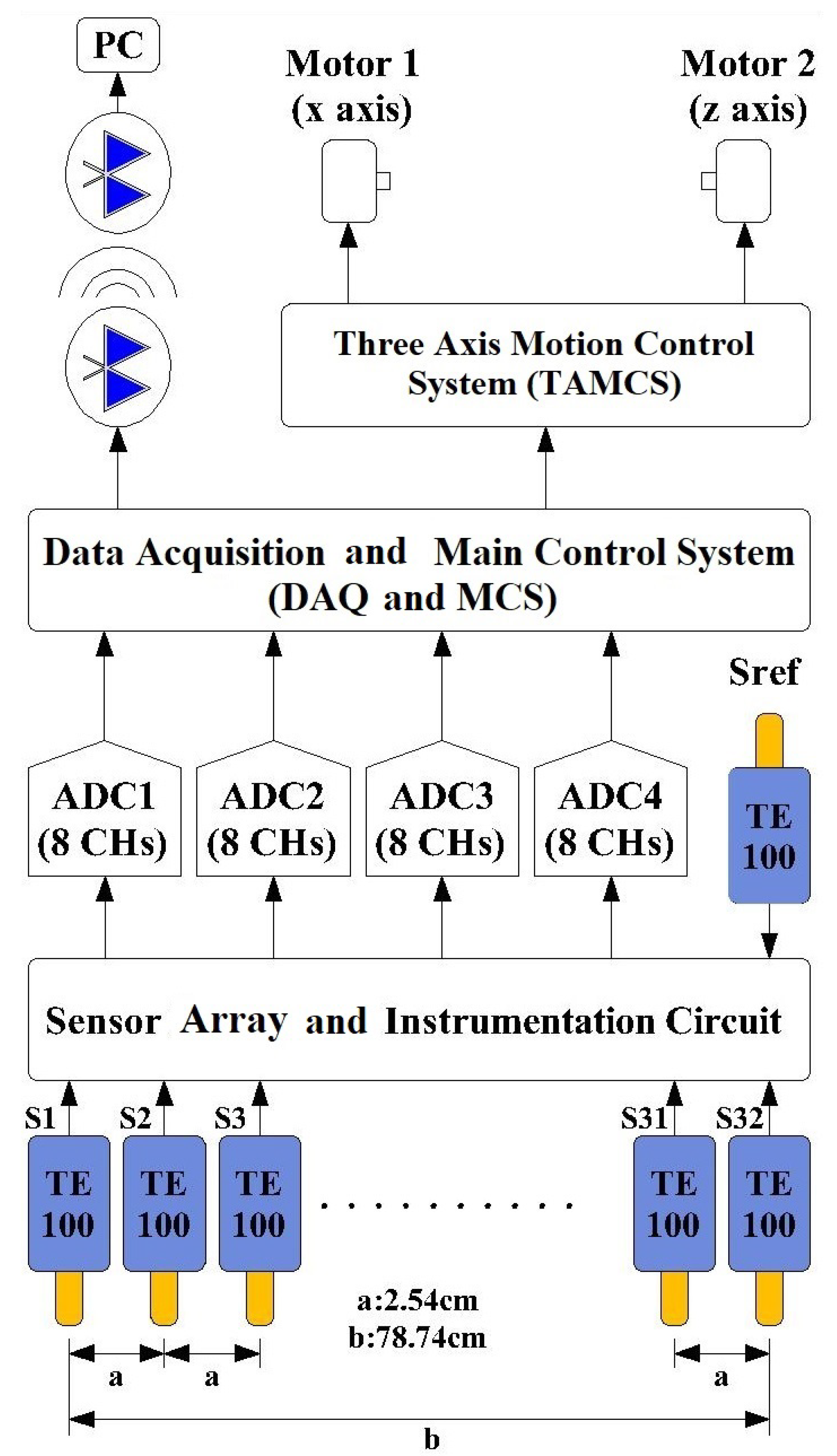
Figure 1. Basic diagram of buried explosive detection (BED) system.
Applsci 09 05415 g001
Figure 2. Appearance of the BED system.
Applsci 09 05415 g002
Figure 3. Appearance of the TE100 fluxgate sensor.
Applsci 09 05415 g003
Figure 4. The basic diagram of the instrumentation circuit.
Applsci 09 05415 g004
Figure 5. The circuit schematic of instrumentation circuit only for one sensor channel.
Applsci 09 05415 g005
Figure 6. Screen appearance of developed graphical user interface unit (GUIU).
Applsci 09 05415 g006
Figure 7. Appearances and physical properties of the explosive samples with standard production.
Applsci 09 05415 g007
Figure 8. Appearances and physical properties of the samples used as cases in improvised explosive devices (IEDs).
Applsci 09 05415 g008
Figure 9. Appearances and physical properties of the non-explosive samples.
Applsci 09 05415 g009
Figure 10. Grey scale graphics obtained as a result of magnetic field scans performed at a distance of 5 cm.
Applsci 09 05415 g010
Figure 11. Grey scale images obtained from 81mm Mortar Ammunition, Sample 6, and Sample 21, at the heights of 5 cm, 10 cm, 15 cm, and 20 cm.
Applsci 09 05415 g011
Figure 12. The x–z projection plots for 60 mm Mortar Ammunition, M16 Anti-Personal (AP) Mine, Sample 3, and Sample 11.
Applsci 09 05415 g012
Figure 13. Steps for creating 32 × 2 data matrices.
Applsci 09 05415 g013
Table 1. Feature groups and elements.
MaxMin σ KCAM
Group 1
Group 2
Group 3
Group 4
Group 5
Group 6
Group 7
Group 8
Group 9
Group 10
Group 11
Table 2. Classification results of kNN for 32 × 25 data matrices.
Feature Groups
1234567891011
k→3 κ 0.50.550.550.640.560.590.640.560.570.530.7
TP6667657070656669676774
FP141315101015141113136
TN3537394035414336383640
FN171513121711916141612
ACC0.770.790.790.830.80.80.830.80.80.780.86
k→5 κ 0.480.480.480.490.550.510.580.610.560.520.57
TP6767626371636370686666
FP131318179171710121414
TN3333373734384238373639
FN1919151518141014151613
ACC0.760.760.750.760.80.770.80.820.80.770.8
k→7 κ 0.420.420.340.570.50.40.60.60.540.420.61
TP6868606670636568696468
FP1212201410171512111612
TN2929313932324239353212
FN2323211320201013172040
ACC0.730.730.690.80.770.720.810.810.790.730.61
Mean Values
κ :0.53 TP:67 FP:13 TN:36
FN:16 ACC:0.78
Table 3. Classification results of kNN for 32 × 2 data matrices.
Feature Groups
1234567891011
k→3 κ 0.820.670.710.80.750.810.870.670.850.890.83
TP7667717877737565757678
FP4139237515542
TN4544434240474946484944
FN7891012536438
ACC0.920.840.860.910.890.910.940.840.930.950.92
k→5 κ 0.670.540.630.750.70.660.790.520.720.820.76
TP7365687474707260747773
FP715126610820637
TN3938414340414741414444
FN131411912115111188
ACC0.850.780.830.890.860.840.90.770.870.920.89
k→7 κ 0.710.530.520.690.720.580.640.480.70.790.73
TP7368667074676561707472
FP712141061315191068
TN4135364341394438434543
FN11171691113814979
ACC0.860.780.770.860.870.80.830.750.860.90.87
Mean Values
κ :0.71 TP:71 FP:9 TN:43
FN:9 ACC:0.86