1. Introduction
Batteries are the most common electrical energy storage device in vehicles as a replacement of traditional fuel (petrol, gasoline) [
1,
2,
3,
4]. The capacity of a battery is gradually reduced due to erosion, passivation, outgassing, temperature, decomposition of materials, and changes on the electrode surface during its operation [
5,
6]. Also, the battery weakening process can be increased when the battery is subjected to operate beyond its specified safe operating conditions. The battery state is also used to estimate the expected lifetime of the battery and can simply be described by two parameters: state of charge (SOC) and state of health (SOH). The SOC mostly depends on current in and out and its initial charge condition of a battery at a given temperature [
7]. The SOH is a measurement that reflects the general condition of a battery and its ability to deliver the specified performance compared to a fresh battery. In smaller vehicles, monitoring the voltage and current of each cell reduces the reliability because of the increased amount of circuitry. Also, these circuits require some power to operate, therefore, they induce a self-discharge. The battery monitoring may have inputs as the total voltage, current, and temperature, but requires a reference point to know that all cells are full. For the battery to have a long life, it requires an appropriate battery management system (BMS) to equalize the cells in a battery string. Several cell-balancing strategies have been presented in the literature [
8,
9,
10,
11,
12,
13,
14,
15]. Slight differences between the series-connected cells in a lithium-ion (Li-ion) battery pack can produce imbalances in cell voltages, and this effect causes great reductions in the charge capacity [
16,
17]. There are three main types of battery management systems that are commonly found in commercial and industrial lithium battery-based systems, such as the shunt resistor equalizing method, capacitor equalizing method, and inductor/transformer equalizing method. The aim is to retain a low bill of material (BOM) and still achieving a fast equalization. In lithium types, the voltage is mainly dependent on the charging state when the battery is either full or empty. The easiest way is to equalize when at the almost-full state. There are multiple balancing systems, which can roughly be subdivided into the following two categories: The active cell balancing method and passive cell balancing method.
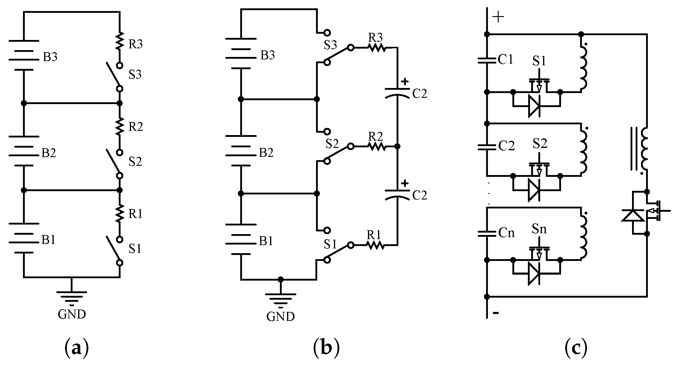
The shunting resistor cell balancing method is a passive method that shunts the charging current around each cell as they become fully charged. It removes excess energy from the higher voltage cells by bypassing the current of the cell, and waits until it is the same level as low voltage cells. This can be categorized into two subcategories: fixed or switched resistor balancing methods [
18,
19,
20,
21,
22]. The first method uses continuous bypassing of the current for all cells. It can be only used for lead–acid and nickel batteries because they have the capability to be in overcharge conditions without damage. The second method is a controlled shunting resistor. This method removes energy from high cells in a controlled manner by using switches. When the unbalancing happens, it will be detected by a sensor that is measuring the voltage across cells that decides what resistor should be shunted. The disadvantages of this method are the requirement for a large-power dissipating resistor, high-current switches, and thermal management requirements. A switched resistor cell balancing is shown in
Figure 1a.
The capacitive shunting balancing method is an active cell balancing method. An active cell balancing employs an active charge shunting element to remove energy from one cell to another cell. The capacitor shunting balancing method can be implemented in the following three categories: switched capacitor, single switched capacitor, and double-tiered switched capacitor [
10,
23,
24,
25]. The switched capacitor has two conditions, charging and discharging. A group of capacitors is used to shift charge among batteries. A single switched capacitor requires only one capacitor to balance cells. A double-tiered switched capacitor balancing method is a derivation of the switched capacitor but it uses two capacitors for energy shuttling. The advantage is that the second capacitor reduces the balancing time.
Figure 1b shows a switched capacitor balancing circuit.
The transformer/flyback balancing method is an active balancing method and removes energy from one cell to another cell [
11,
12,
13,
15,
26,
27,
28]. It may have a smaller balancing/executing time. It also has disadvantages, such as high cost and magnetic losses.
Figure 1c shows the multi secondary winding transformer balancing method. If all transistors are always switched at the secondary side, the leakage impedance determines the equalizing current for a voltage difference. It is not clear if all secondary voltages are equal due to the non-homogeneous field close to the air gap on the flyback transformer. If only some selected transistors are driven, more precise control is possible, but this requires much more circuitry.
In this paper, a high-voltage detecting, equalizing, and monitoring system is proposed. To achieve that, a light-emitting diode (LED) band gap is used as a voltage reference to inform the user if any cell is at its high voltage. A smart-monitoring display (using a liquid crystal display (LCD)) shows the user whether one cell is high or all cells are high. This provides a signal to the microcontroller to turn on/off the charger if all cells are high as well. Furthermore, a Bluetooth module is designed to command the microcontroller to turn on/off the charger via voice/text message by using a smartphone. A notable characteristic of the system is its ability to carry a very-low current; as a result, the system does not contribute significantly to the self-discharge of the battery and does not require complex control as compared to the existing passive methods [
21,
22,
29].
2. Smart High-Voltage Equalizing Detection
In this section, the principle of high-voltage equalizing detection (HVED) via an LED band gap, based on the voltage reference, will be considered. This paper proposes both an equalizing and monitoring system. The monitoring system detects if one cell is fully charged or all cells are fully charged and the equalizing system tops off each cell at the desired voltage. To achieve this, a light-emitting diode (LED) band gap is used as a voltage reference to detect the cell voltages and to inform the user if any cell is at its high voltage. Also, a smart-monitoring system using a liquid crystal display (LCD) displays to the user if one cell is at the desired high-voltage level or if all cells are at the desired high-voltage level by displaying the text messages, “one cell is high” or “all cells high” on the LCD. This detection also gives a signal to the microcontroller to turn on, or to turn off the charger if all cells are at high-voltage level. In addition, a Bluetooth module was designed to command the microcontroller to turn on or to turn off the charger via voice or text message by using a smartphone. Other technologies were tried out, such as supply level detectors, but these had an even higher cost, the leakage current was higher, and the voltage accuracy was lower.
Typical Zener diodes do not have a very sharp knee as the threshold voltage for equalization (discrete or integrated circuit e.g., LM329). The aim is to obtain a low-leakage current at low voltage (below threshold voltage) and high-equalizing current at a constant voltage, or simply put, a sharp knee in the I-V characteristic. The most often used integrated circuit (IC) in commercially available BMS systems is a three-terminal TL431, in which the third terminal is used to set the voltage. However, a minimum regulating current of 400 A is required, with a voltage divider needed to get an adjustable output voltage. With a 2.495 V reference (1%) and the assumption of a 10 k reference resistor in the voltage divider, this requires 0.2495 mA. This causes a 2.185 Ah capacity decrease in one year, and usually, there are also other leakage currents in a system. For the newer technologies, such as the junction gate field-effect transistor (JFET) pinch-off references, this problem arises with a 560–800 A quiescent current for the ADR 430 series. While obtaining a high accuracy, low-temperature coefficients, and noise, JFET pinch-off references cost more. One of the most recent entries in the voltage reference sweepstakes is a floating gate voltage reference. The idea here is to introduce some charge into the buried and well-insulated gate of a metal-oxide-semiconductor field-effect transistor (MOSFET) during manufacturing, thereby putting it at a certain voltage. The ISL21009 series exhibit a typical regulating current of 100 A, which is acceptable.
3. Proposed Topology and Operation
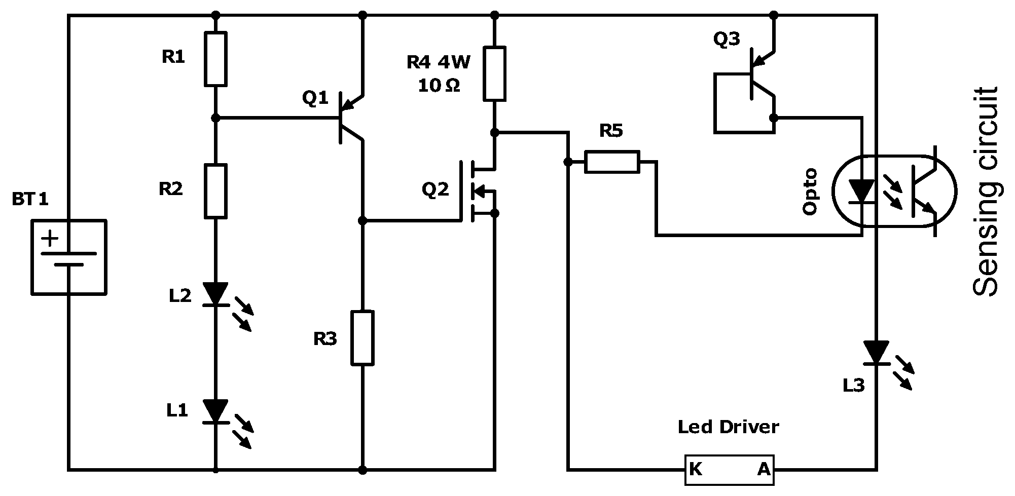
The operational principle for one cell is illustrated in
Figure 2. Assume that the voltage of the considered cell rises above a predefined maximum value. At this moment the two LEDs in series (L1, L2) become forward biased, enabling the transistor Q1, bipolar junction transistor (BJT) (PNP) to be turned on. The gate of the N-channel MOSFET Q2 gets pulled up and current flows through the 4W resistor. This is a power resistor since it needs to dissipate the surplus battery power for some time.
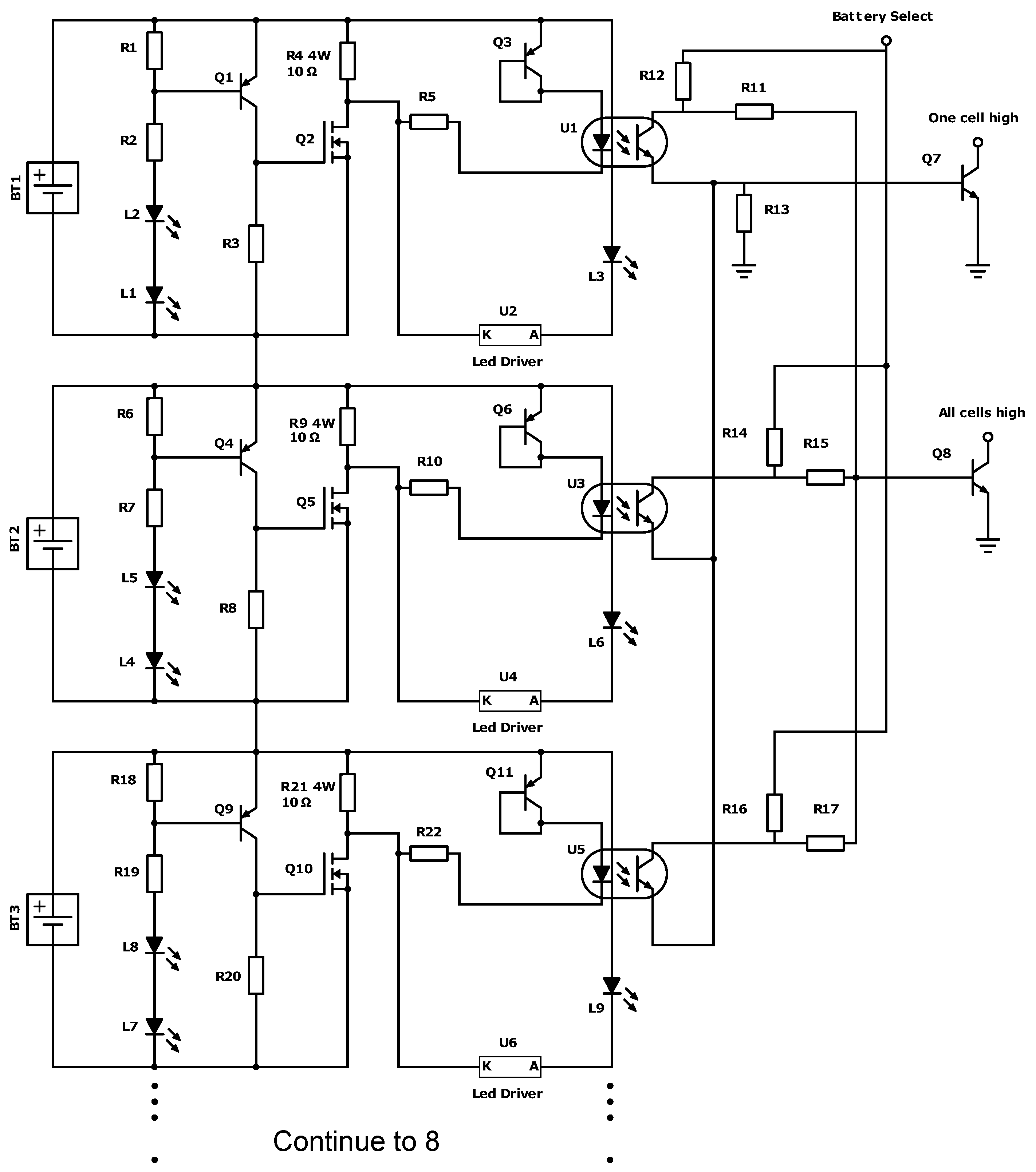
An extra LED is used to inform users that the system is in high-voltage equalization. The LED driver/constant current regulator limits the current to 10 mA and has a negative T-coefficient to protect the LED from thermal runaway at high currents. Note that it tops all cells at a predefined voltage. A detection is added to enable actions, such as balancing and charger cut-off when the cells go beyond the threshold voltage. This detection is located on the right-hand side of the schematic. The over-voltage detection is implemented through an optoisolator, (optocoupler) shown in
Figure 3.
For servicing, it is better to know which cell did reach full charge, thus, a visible LED was implemented. As a cell achieves a high voltage, the phototransistor is switched on and allows the conduction of the collector–emitter current. A wired “Or” circuit, using transistor Q7, allows the detecting of whether one cell is high and a wired “AND” circuit using Q8 detects whether all cells are high. This current originates from a bank- or battery-select, which is a microcontroller signal (5 V) enabling the monitoring of the different battery packs at a certain frequency. This way the amount of signals is reduced from four to one as the packs are not simultaneously monitored, but sequentially monitored. The frequency must be made high enough in order to make sure that during non-monitored dissipation, the cell will not be damaged. In addition, a Bluetooth module is predicted to command the microcontroller to turn on or off the charger when all cells are high via a voice or text message by using a smartphone. Depending on the fastest charger type (within the current limits of the batteries), the resistor might vary.
Assume only one HVED cell (assume again cell 1) in the pack has reached equalizing mode, or simply put, one cell is high, then the collector of the Q7 BJT is pulled down, enabling a microcontroller to interpret this pull-down as a warning that one cell is high. Please note that the controller has no means of detecting which specific cell is high, thus, the LED is useful for maintenance and fault detection. This information can then be used to disable the charger temporarily and balance the cells amongst each other through a parallel balancing method. During regenerative braking, this method is also used. When all cells are high, the collector of the Q8 BJT is pulled down and the microcontroller is warned that all cells are high. This case will probably only happen when regenerative braking. In a charging situation, most chargers (without individual cell monitoring) will stop when the average peak voltage is high enough, though some cells might be rather low and at the same time other cells too high. By doing this, an important reduction of wires is obtained toward the processor. It can even be further reduced by multiplexing data from series-connected battery sets.
4. Practical Implementation
In this section, the practical implementation of the HVED circuit will be discussed. In our first design, the LEDs were chosen in such a way that the threshold voltage for equalization was very close to 3.65 V. This was done by selecting gallium–arsenide–phosphide LEDs. It seems to be an ideal situation since the maximum charging voltage of the lithium–iron–phosphate (LiFePO) cells, as declared by the manufacturer, is 3.65 V (+/−0.05). However, in LiFePO technology batteries, this limit is less strict than in li–ion batteries since the electrolyte does not decompose quickly and there is much less risk of thermal runaway. This makes a trade-off between a slight overcharge and a resulting decrease in cycle-life possible.
There are some reasons to select a higher threshold voltage than 3.65 V. First of all, assume the batteries are to be charged to their full charge. This means all cells should reach 3.65 V. Equalization at this threshold is rather hard to obtain. Anyhow, there is a variety of LED types that are able to get the right effect. Assume that normal charging stops at one cell high. A trickle charging can give a reduced current that HVED circuits can manage. One way is to switch to a trickle charge mode, where a limited current of, for example, 1%, of nominal Ah is given. In this way, the voltage-limiting can fully act without the risk of overcharging. At the end of the trickle charging all HVED units are warm, coming in under the higher-temperature threshold.
The LEDs (≈1.5 mV/K for Al-GaInP) and BJT base-emitter junction (≈2 mV/K) both have a negative temperature coefficient causing the threshold voltage to decrease when the temperature rises. The HVED will equalize earlier than required at higher temperatures. It can be seen as a positive effect since a higher temperature puts stress on the cell. As explained before, it makes it harder to reach full charge, and limits the obtainable range of the vehicle. One could argue that the open-circuit voltage OCV vs. SOC characteristic is also temperature-dependent, but not in the same temperature range. LiFePO
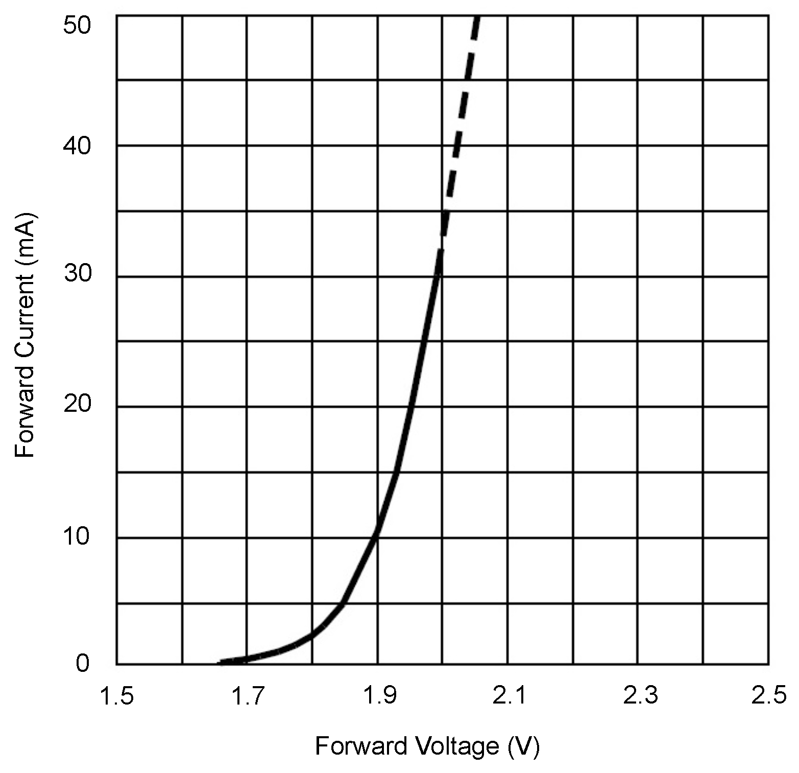
batteries have a higher tolerance to overcharge. There is a capacity decrease due to active material loss inside the cell. The type of LED is a choice requiring some thought if some designers want to use a lower threshold LED, as such types also exist. A rather high threshold voltage is chosen by using aluminum–gallium–indium–phosphide LEDs. Since the purpose of the LEDs is not to emit light, it is not the forward voltage drop mentioned in the data-sheet (1.95 V–2.5 V at 20 mA and 25
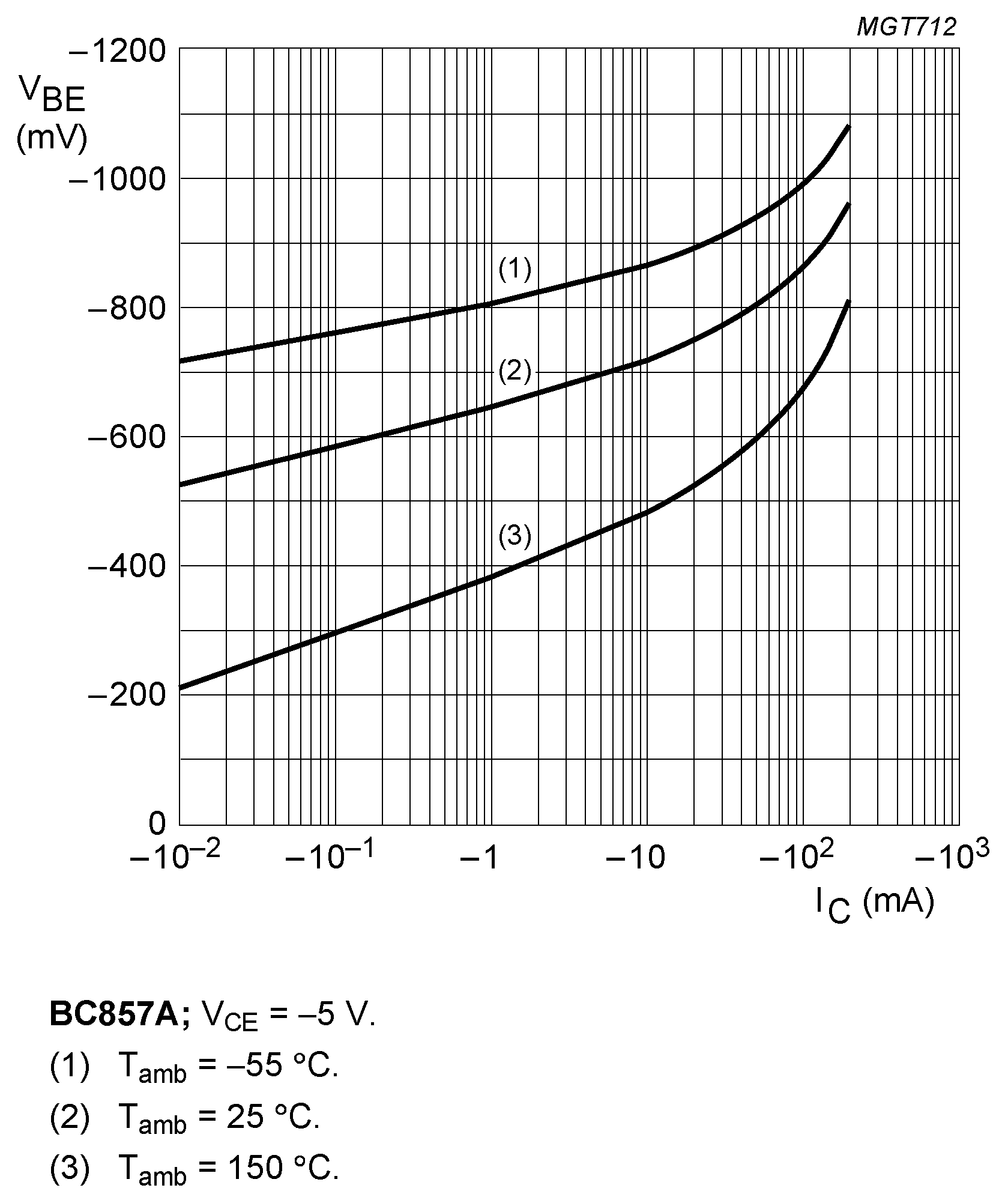
C) that has to be considered, since the HVED will start working at lower currents and thus lower forward voltages. One could determine the forward voltage drop by making use of the Schottky diode equation and Ebers–Moll model, but this would unnecessarily complicate matters. The estimate for the LED drop is made from the following characteristic as supplied by the manufacturer. The reverse leakage current is also an indication of the forward leakage current. Next to the LED drop, the threshold voltage is also determined by the base-emitter voltage drop of the PNP BJT. The LED supplier specified a reverse LED leakage of 10
A. In the assumption of a forward leakage <10
A, the BJT has to be biased sufficiently above that value, so the leakage in no way triggers the equalization. A 10 k
base-emitter resistor is chosen to be safe in that regard. The current will stay well below 1 mA and the LED drop can thus safely be assumed around 1.65 V according to
Figure 4. The transistor works at a limited collector current of <0.1 mA, the threshold
can be estimated at 0.55 V according to
Figure 5.
The threshold voltage obtained by this configuration is estimated as the following equation
Due to the use of the 10 dissipating resistor, and of the MOSFET, the equalizing current is limited below 370 mA. One could consider using a lower resistance to speed up the dissipation of energy from the high cell, however, there is no need to quickly dissipate, and a larger dissipation current would require the cooling size of a printed circuit board (PCB) heat sink. A 370 mA equalizing current means a 1.3% dissipative equalization per hour. The HVED will also be active during regenerative braking. A 370 mA equalization current gives a 48.64 W power dissipation. This is not sufficient for mountain terrains with a full battery pack; the user will be informed that they better use the mechanical brake. However, as in a charging situation, the control sequence will be programmed to only enable regenerative braking if required.
5. Experimental Results
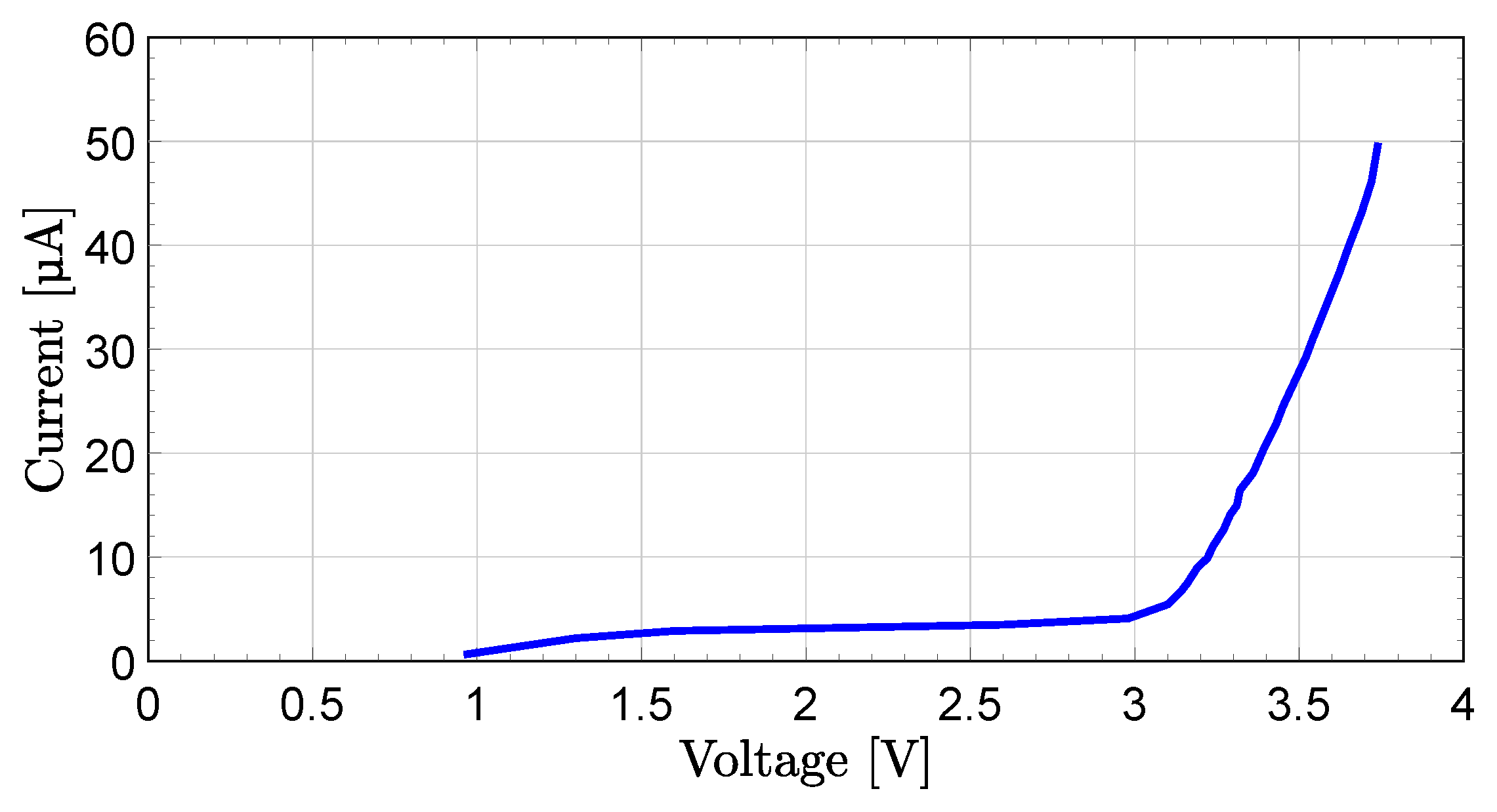
In this section, the functionality of the above design was tested and conclusions concerning the results are made. In all of the following tests, capacitors were connected in parallel to each HVED cell to simulate the series impedance of a battery cell. Since one of the design goals is to obtain a voltage reference that distinguishes itself compared to other voltage references in its quiescent behavior, the HVED was first tested at sub-threshold voltages. A 1 M resistor in series with a 56 k resistor was used in parallel with the 20 M internal resistance of the voltmeter to obtain a 1.003 M current measuring resistance. The cell voltage was measured on the PCB. The following result of a single HVED cell was obtained.
From
Figure 6, it is clear that the quiescent current at the nominal voltage is below 10
A (9.87
A to be precise). On a yearly basis, this means a capacity decrease of 0.3%, which is considered to be an outstanding result. From there on out the knee starts to form with a 41
A current at 3.65 V, sufficiently small enough to assume a sharp knee. To observe this characteristic at higher currents, initially, a single HVED cell was tested to above 400 mA. A large number of data points were selected over a 10 min measurement to indicate the temperature influence on the HVED cell voltage. In
Figure 7 the result is shown.
The cold threshold voltage amounts to 3.86 V, which is a fraction higher than the 3.85 V that was estimated in the previous section. Due to the temperature coefficient of the LED and BE-junction of the BJT, the HVED cell voltage at 390 mA is reduced to 3.81 V. This results in a 10 C temperature increase. Above 380 mA, the voltage rises again as is foreseen due to the presence of the 10 dissipation resistor. A 10 C temperature increase is something very common in any vehicle if parked in the sun, for example. Temperature differences of up to 30 C are likely.
This would lead to a 0.15 V reduction in the threshold voltage. For a design with a 3.65 V threshold, the warm threshold would thus be 3.5 V, which is still well above the nominal voltage. Depending on the influence the overcharge has on the batteries, this method can still be opted to decrease the threshold voltage. This influence is to be evaluated in a later phase. In order to draw a conclusion regarding an entire pack of HVED cells, all eight cells were tested simultaneously to observe if the threshold voltage and I-V characteristics show mutual differences.
If there is a faulty cell between the normal cells, it will be detected by the LED at the end of the circuit for each cell shown in
Figure 2, as well as the voltage-sensing circuit as shown in
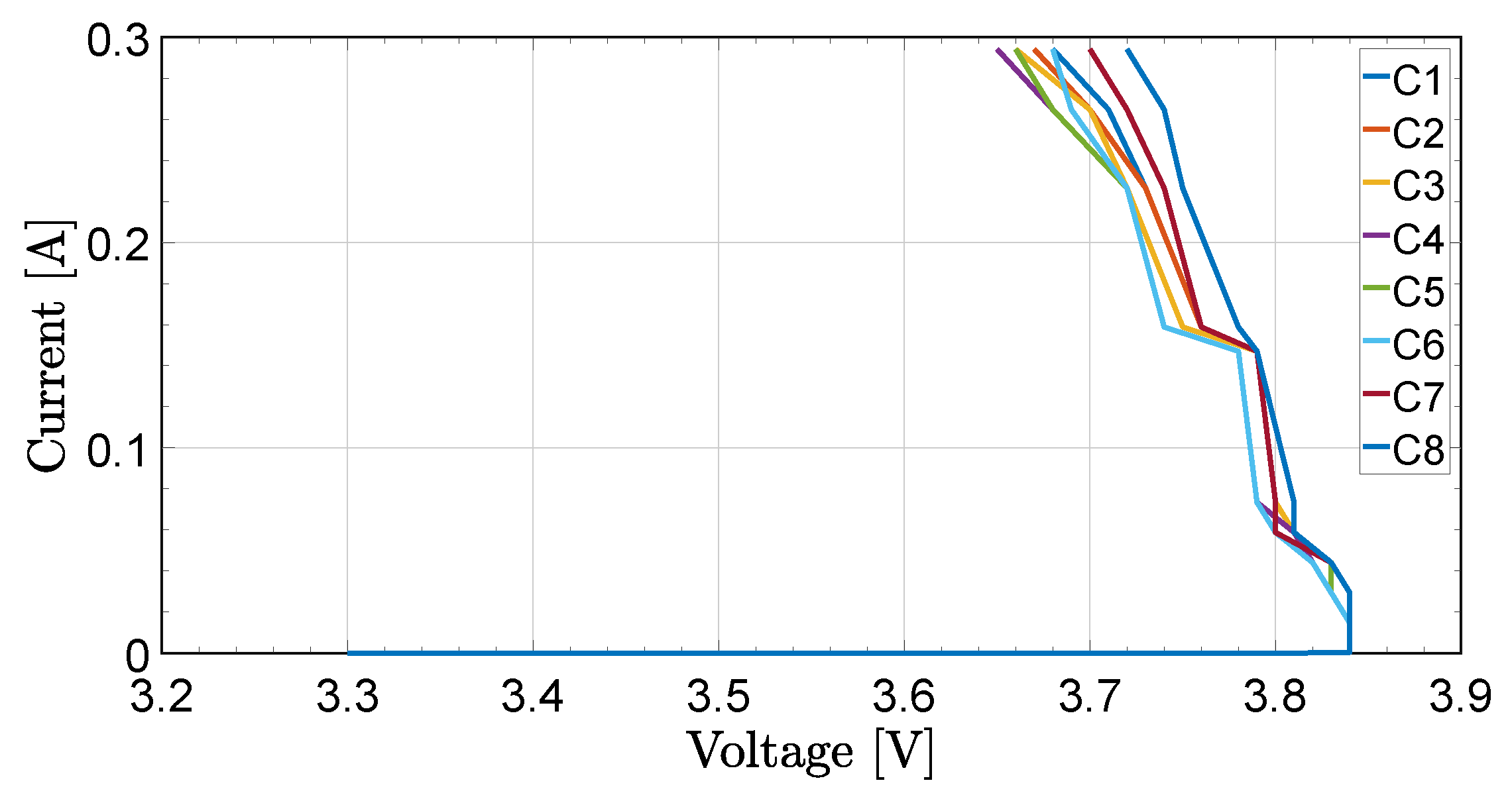
Figure 3. A large voltage range is represented in order to examine possible differences between cells in quiescent and equalizing mode. The obtained result is represented in
Figure 8.
In this case, the lowest HVED cell voltage at a supply current of 294 mA is 3.65 V in cell 4 (C4), with the highest being 3.72 V in cell 8 (C8). There is a noticeable increase in mutual differences between cells at higher currents. When assessing the differences, it is clear that cells located in the middle of the PCB are affected by the heat production of the surrounding cells and show a larger temperature effect than the border cells. One would expect that the voltage of cell number 8 and cell number 1 show little difference, which does not correspond to the measurement.
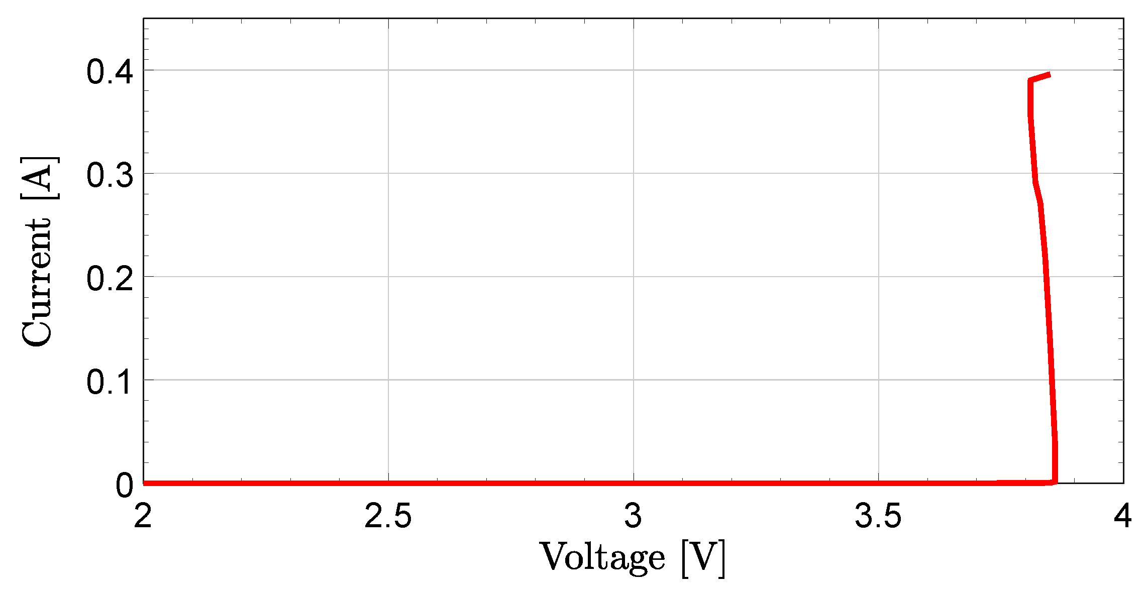
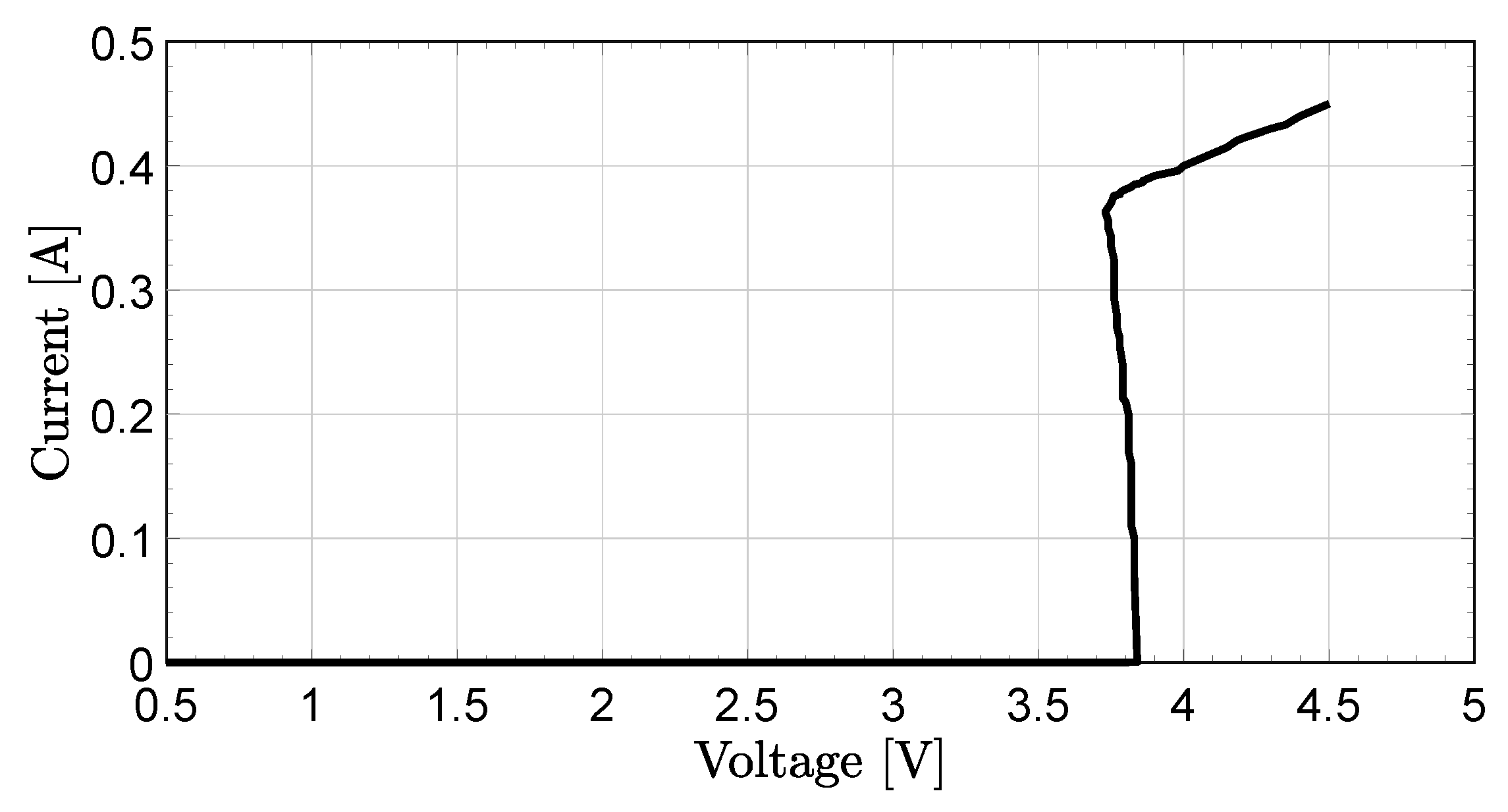
This is due to the testing setup. The resistor used to obtain the supply current also generates heat with increasing current. In the test, this resistor was located nearest to cell 1, thereby explaining its increased voltage drop. In
Figure 9 the I-V characteristics of one cell is presented. It can be seen that The threshold voltage is 3.86 V but due to the temperature coefficient of the LED and BJT, the HVED cell voltage at 390 mA is reduced to 3.81 V. Again above 380 mA, the voltage rises again due to the presence of the 10
dissipation resistor.
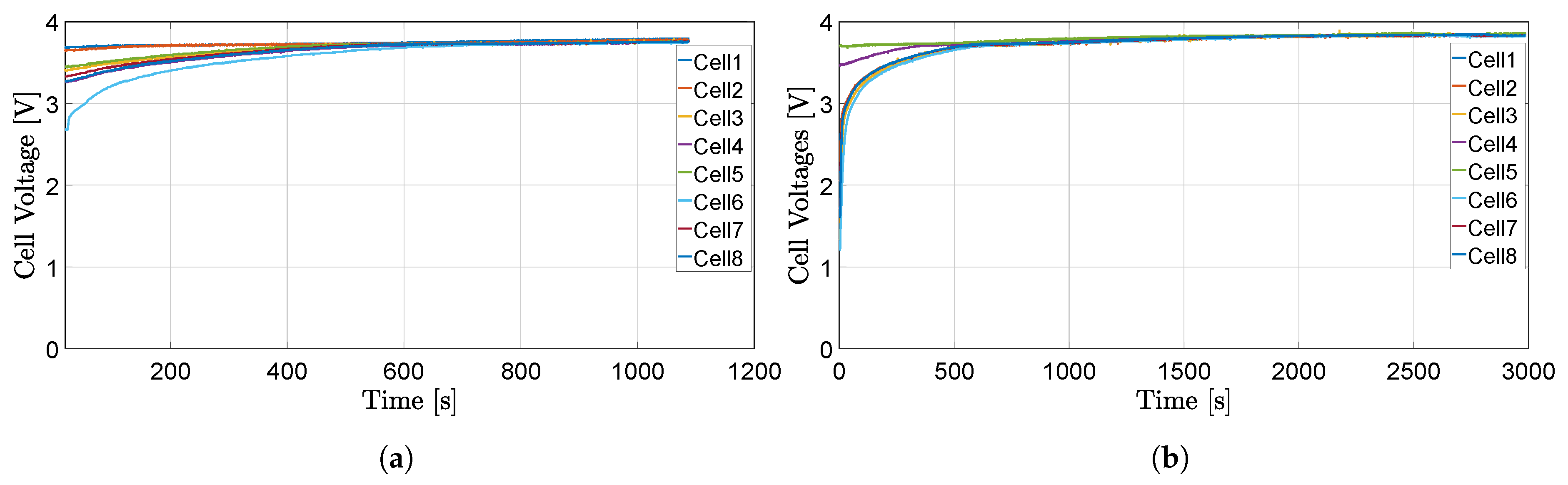
In order to verify the feasibility of the system, the equalization results of eight battery cells are presented. In
Figure 10a, cell voltage waveforms vs. time is shown. The cell voltages vary from 2.67 V to 3.67 V. In this case all cells are above 3.25 V, only one cell is 2.67 V. The cell were fully charged to 3.45 V. As can be seen in the figure, all cells are fully-charged and they are converged at the end of balancing process. In order to test the limit voltage level of the proposed circuit and have more cell imbalances, the circuits were tested with more voltage imbalances. The cell voltages vary from 1.21 V to 3.7 V. The results are shown in
Figure 10b. In both cases the charging current was 1 A. It can be noticed that all cells are charged to the threshold voltage 3.85 V according to Equation (
1).
6. Communication between Battery and Charger via Bluetooth Module
As an additional work, a Bluetooth module HC05 was added to the circuit to turn off the charger via a voice message from a smartphone—which is programmed by Arduio Uno—if all cells are fully charged and all cells are at a high level of charge and also turn on the charger if the cells are at a low voltage level. In order to control the charger via Bluetooth module, a mobile app “BT Voice Control for Arduino” is used. This app is available in the Google Play store. If a cell is high, it will be detected by the circuit at the end of each battery section transistor Q7 as shown in
Figure 3 and if all cells are high it will be detected by transistor Q8 as shown in
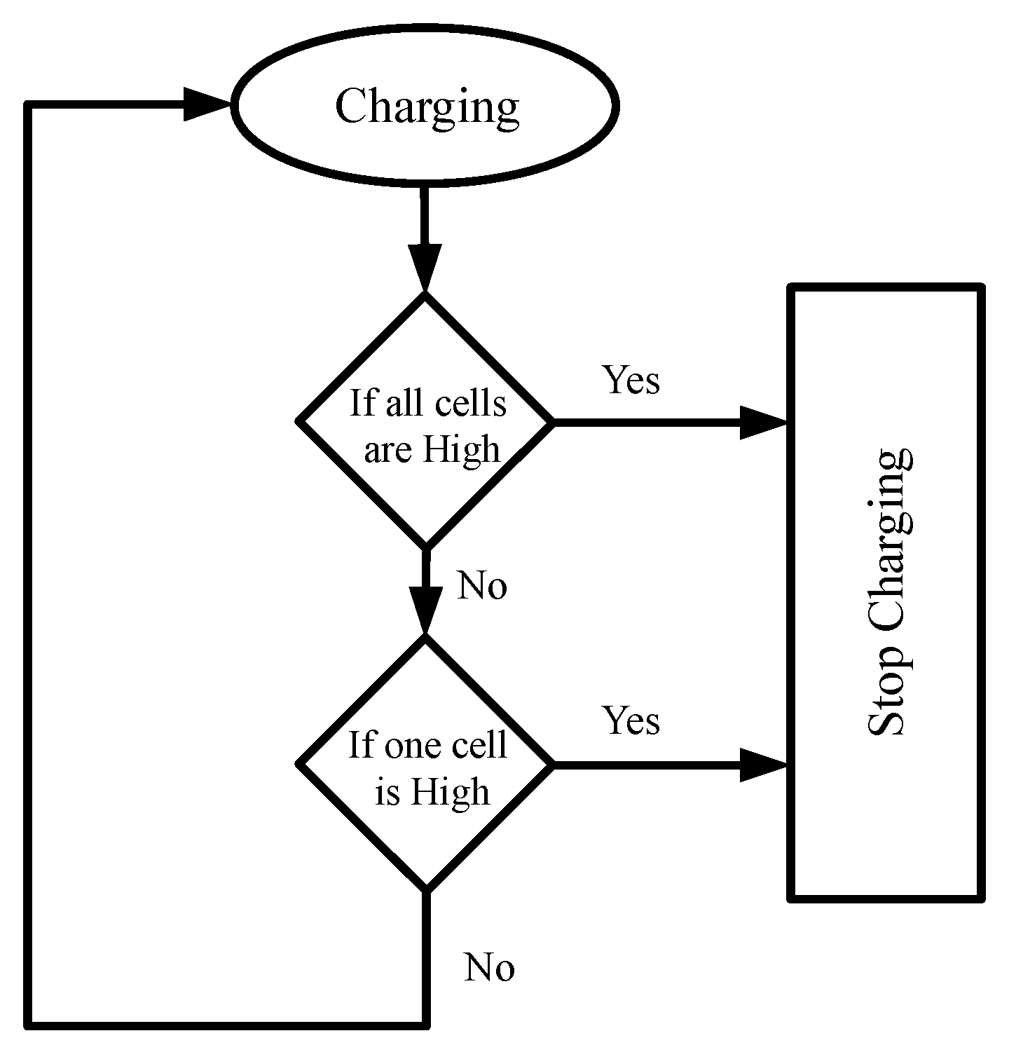
Figure 3. These transistors provide a signal to the analog pin of the microcontroller (Arduino) in order to turn off charging process. These detections are displayed by the LCD using the text “all cells high” or “one cell is high”. It can also be observed by LED for each cell when the LED is turned on, it means this cell is at its high level. If one LED is not turned on it means that the cell is not high or it is damaged. The algorithm flowchart of smart monitoring is presented in
Figure 11. Firstly, it detects if all cells are high, if it is true, it stops charging, if its not it countinues to next stage. Next, if one cell is high it stops again charging, if it is not it countinues charging.
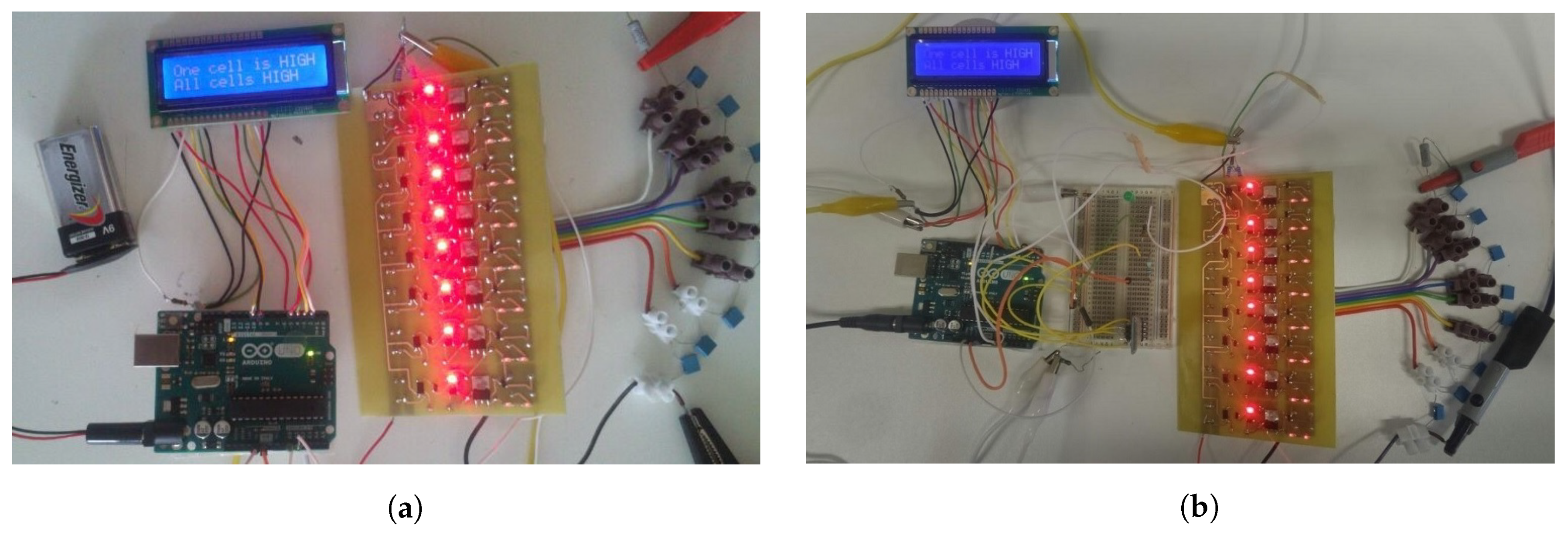
A picture of the testing layout is represented in
Figure 12a. As can be seen in the figure, an LCD is expected to warn the user if one cell is higher than the desired voltage or if all cells are higher than this voltage. To avoid too much self-discharge by this feature, it can turn off itself after 10 days. If it draws <1 W for 10 days it is 0.24 kWh, which is reasonable. It also avoids that the battery stays at its maximum charge level when for some reason it is not used during the month.
A picture of the testing layout with Bluetooth module is represented in
Figure 12b. The state of charge of the cells is also detected by the microcontroller, so if all cells are at a high level of charge it automatically turns off the charger by sending a signal to the charger. It can be done both automatically by the microcontroller and also by voice message from the smartphone. The voice message can be generated by the smartphone with a mobile app “AMR-Voice”, which is available in the Google Play store, then this message will be received by Bluetooth module HC05 which is connected to the Arduino, thus, the Arduino will disconnect the charger. In this paper, eight cells are considered, but the number of cells can be extended by adding more parts to the whole circuit, which are all the same and connected in series, but for simplicity, one circuit is shown in
Figure 2.
To monitor individual cell voltage, a new smart-monitoring system based on Bluetooth was made. The system provides users to monitor the cell voltages of the battery pack from a safe distance. The smart-monitoring system has played an important role during the last few decades [
30,
31,
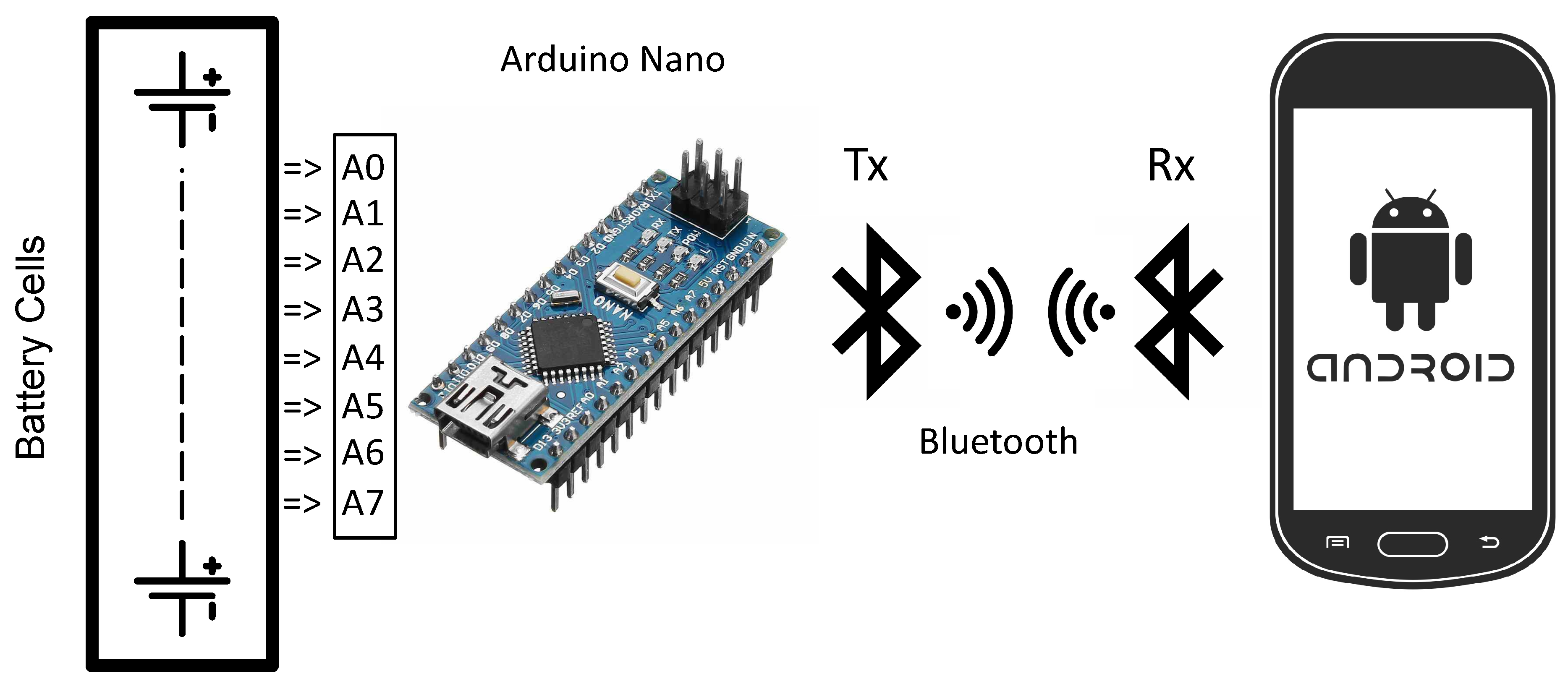
32]. The system was designed using the Arduino Nano as a microcontroller, a Bluetooth module (HC05), and a smartphone. This microcontroller is cheap and capable of measuring eight cell voltages by eight analog pins (A0–A7), which is suitable for our special purpose.
The Bluetooth module is HC05 which is a wireless device. To monitor the cell voltages, first, the individual cell voltages are measured by analog pins of Arduino Nano via isolated voltage probes, and then the data will be transmitted wirelessly by Bluetooth module to a new android application. The smartphone will receive the data from the Bluetooth module, and the measured cell voltages will be displayed on the smartphone screen. The proposed monitoring system is shown in
Figure 13.
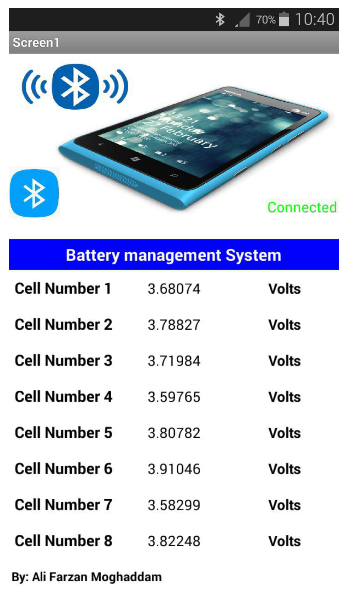
This new android smartphone application is developed by MIT App inventor 2. This application is an open-source platform available on Google. The cell voltage monitoring results are shown in
Figure 14. It can be seen in the figure that the monitoring system will measure cell voltages of eight battery cells in a series.
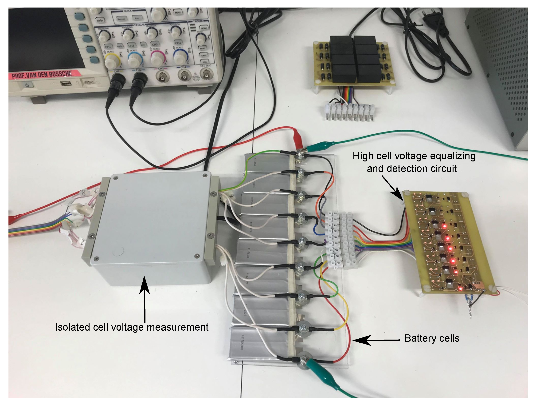
In
Figure 15, a picture of the practical implementation of the proposed circuit is represented. As it can be seen in the figure, eight batteries are connected in series. The cell voltage varies between 3 V to 3.85 V. When a cell reaches the maximum allowed voltage, which is designed to be 3.85 V, the LED will be turned on and the circuit gives a signal to the controller to cut-off the charger. In the figure, cell 1 and cell 2 are not fully charged and the proper LED is turned off, while the other cells are fully charged and the proper LED is turned on.
7. Conclusions
In this paper, a high cell voltage equalizing and detection circuit for a LiFePO battery for an ultra-light electric vehicle is proposed. The battery pack consists of eight cells in series with a nominal voltage of 3.3 V. By applying a two LED band gap, a sufficiently correct voltage is obtained—1.65 V for each LED (connected in series). It shows a sharp knee and very-low leakage current compared to other known techniques, so that the self-discharge due to the BMS becomes negligible. On one hand, if the voltage of an individual cell is higher than the expected value, the excess power is delivered to the 4 W resistor (operated at 2 W). It also gives a signal that we have reached the limited voltage. On the other hand, if all cells are high, it also generates a signal to the optocoupler. These detections are displayed by an LCD and also with LEDs mounted on each cell to inform the user that of what condition the battery charge is in, and gives a signal to the charger to revert to a trickle charge of 0.3 A if one cell is high, or to switch-off charging completely if all cells are high. The detection will appear on the LCD with the text message, “One cell high” if one of the cells are at a high level or “all cells high”; the LEDs mounted at the end of each circuit will also be turned on if the corresponding cell is high. As an additional work, a Bluetooth module (HC05) is predicted to command the microcontroller to turn on or off the charger via a voice or text message by using a smartphone when it is desired to be turned off or on. This voice message is provided by phone and it will be received by Bluetooth module which is connected to the microcontroller (Arduino). If a cell is replaced in a battery that does not have the same charge as the other cell, it will cause any issues but will just take more time to equalize, no cell will be damaged. To complete the monitoring system, a new smart-monitoring system based on Bluetooth and a new mobile application designed by “MIT app inventor 2” has been made to monitor individual cell voltage. A significant feature of the system is to draw a very-low current hence, the system does not contribute significantly to the self-discharge of the battery. Manufacturers of large electric vehicles may possess more intelligent systems that may need a constant connection to the grid and allow high standby losses, where more percentage of SOC may be lost per day. The paper is rather focused on the reduction of the standby losses and to activate the equalizer only when charging or driving. Experiments were performed to confirm the validity of the proposed system.


