Synthesis and Processing of Melt Spun Materials from Esterified Lignin with Lactic Acid


Abstract
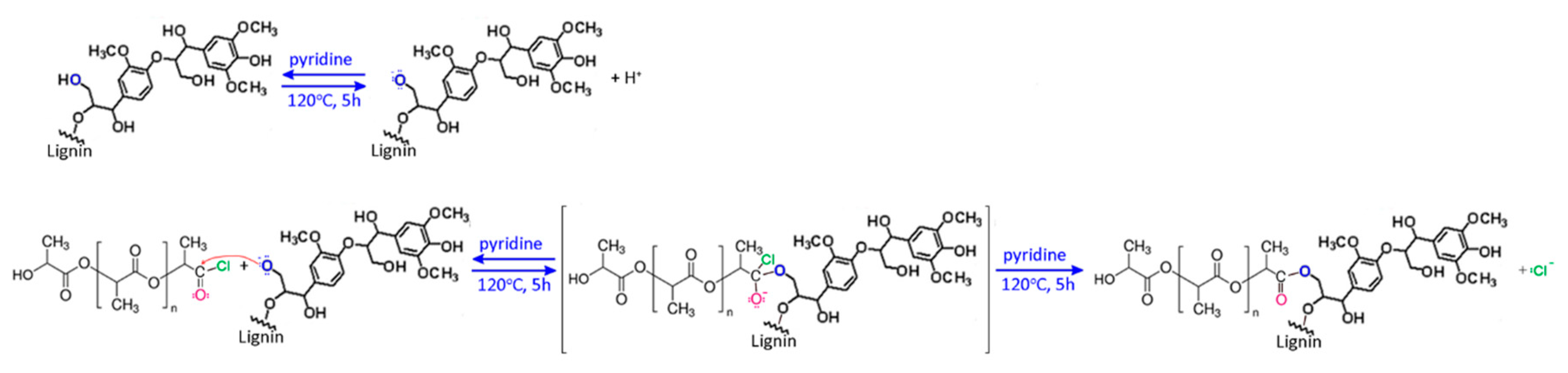
1. Introduction
2. Materials and Methods
2.1. Materials
2.2. Synthesis of Fibers
2.3. Characterization
3. Results and Discussion
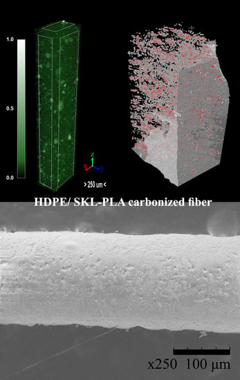
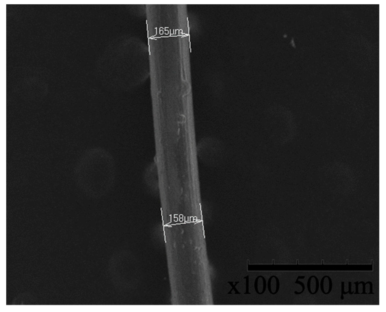
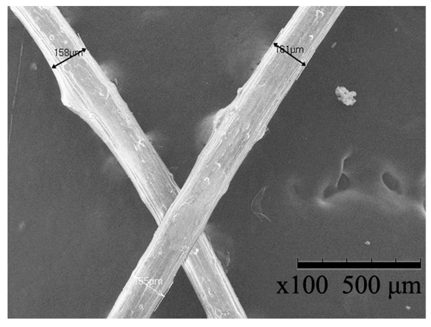
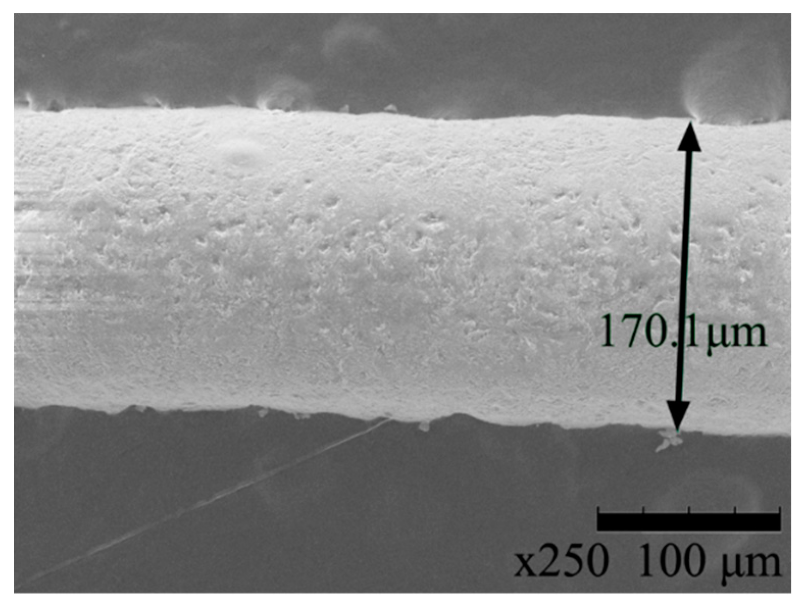
3.1. Scanning Electron Microscopy and Energy Dispersive X-ray Spectroscopy
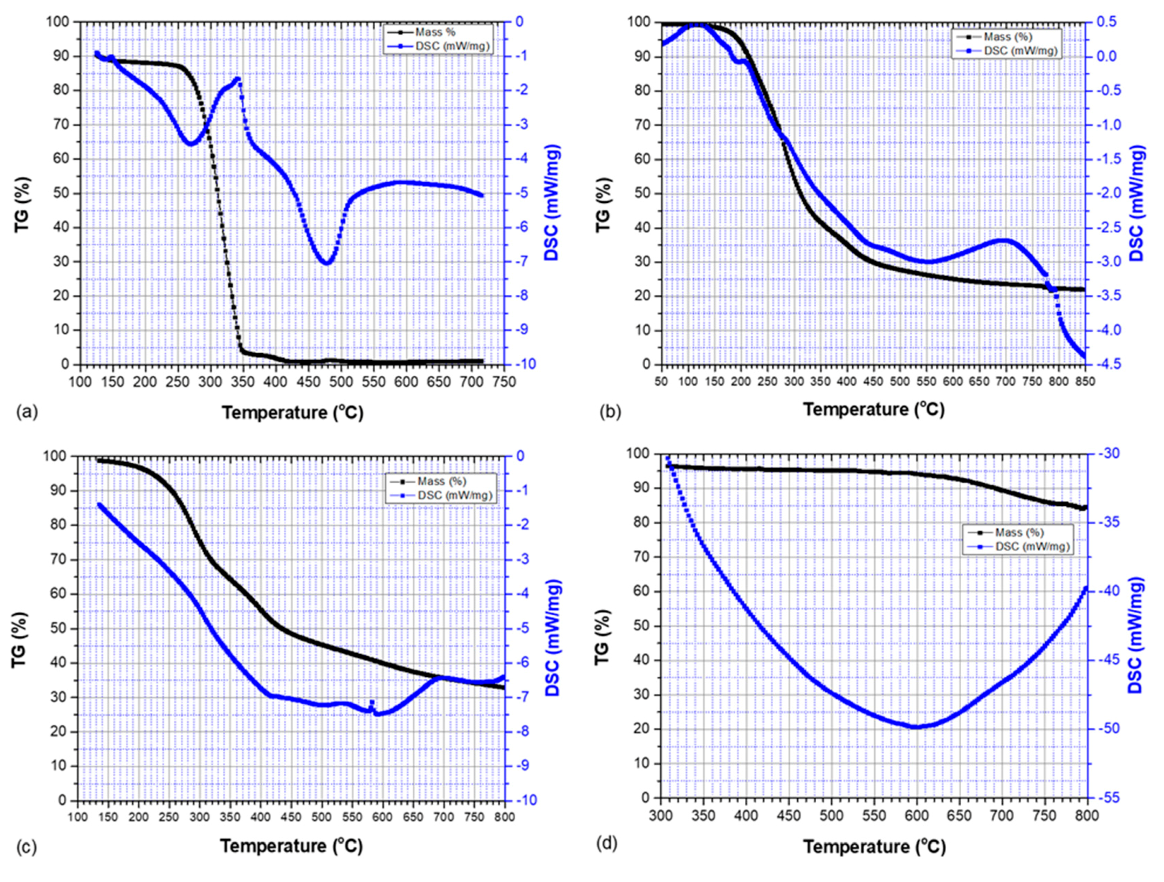
3.2. Thermogravimetric Analysis and Differential Scanning Calorimetry
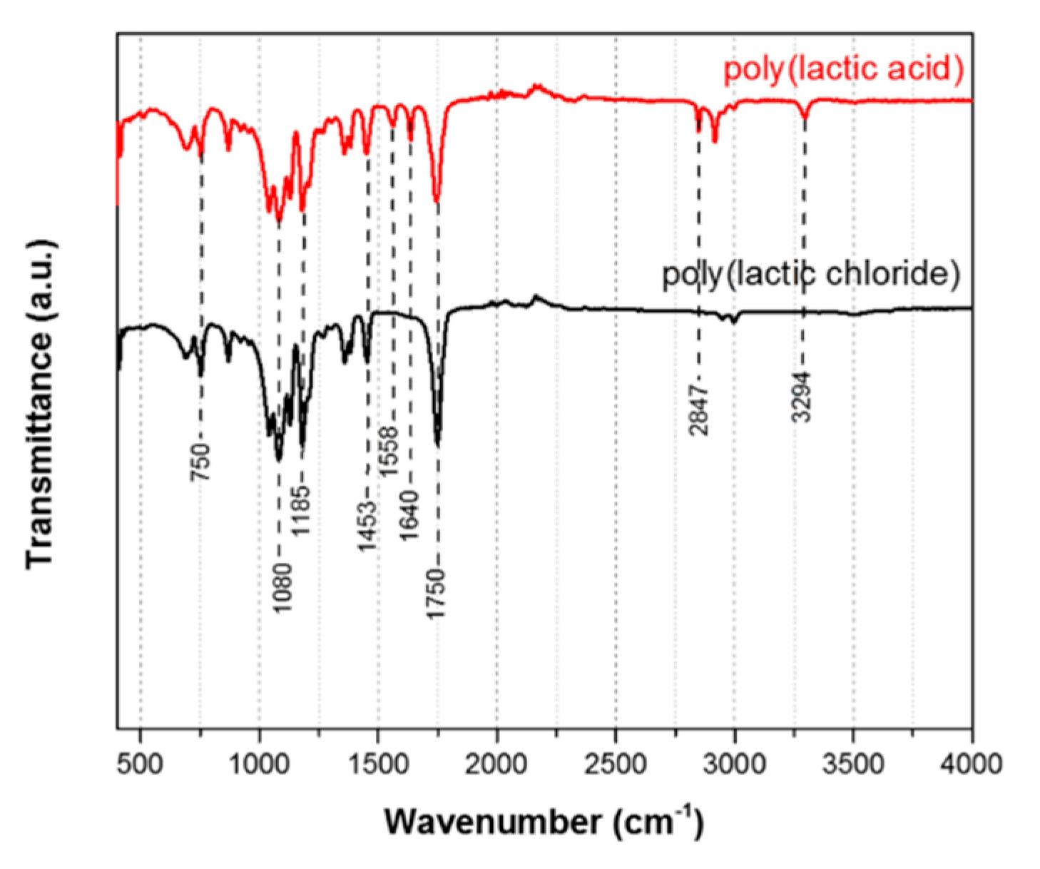
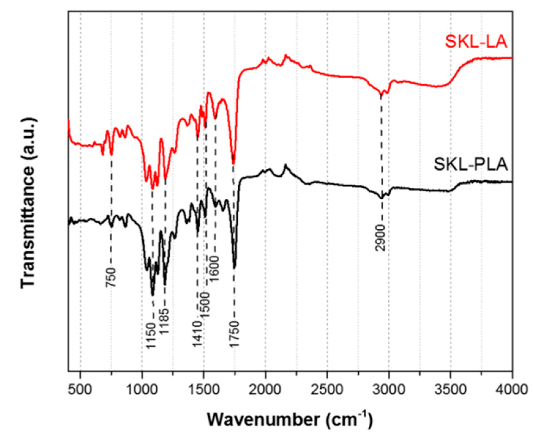
3.3. Attenuated Total Reflectance Fourier Transform Infrared Spectroscopy
3.4. Thermal Processing (Stabilization—Carbonization)
3.5. Tensile Testing of Precursor Fibers
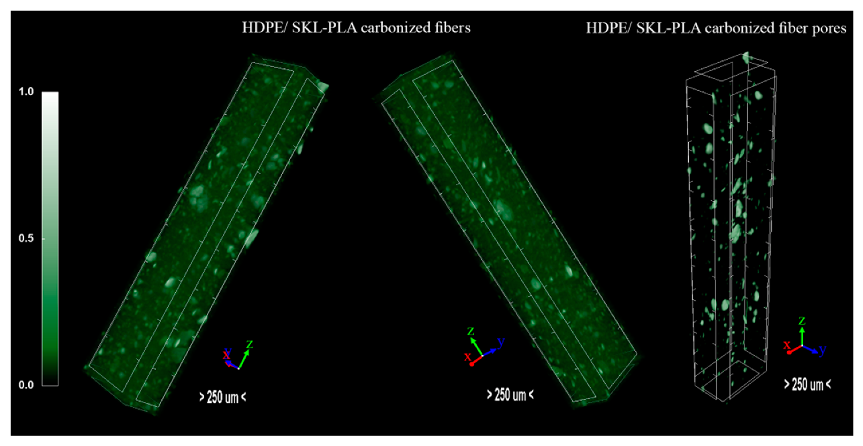
3.6. Micro-CT Analysis
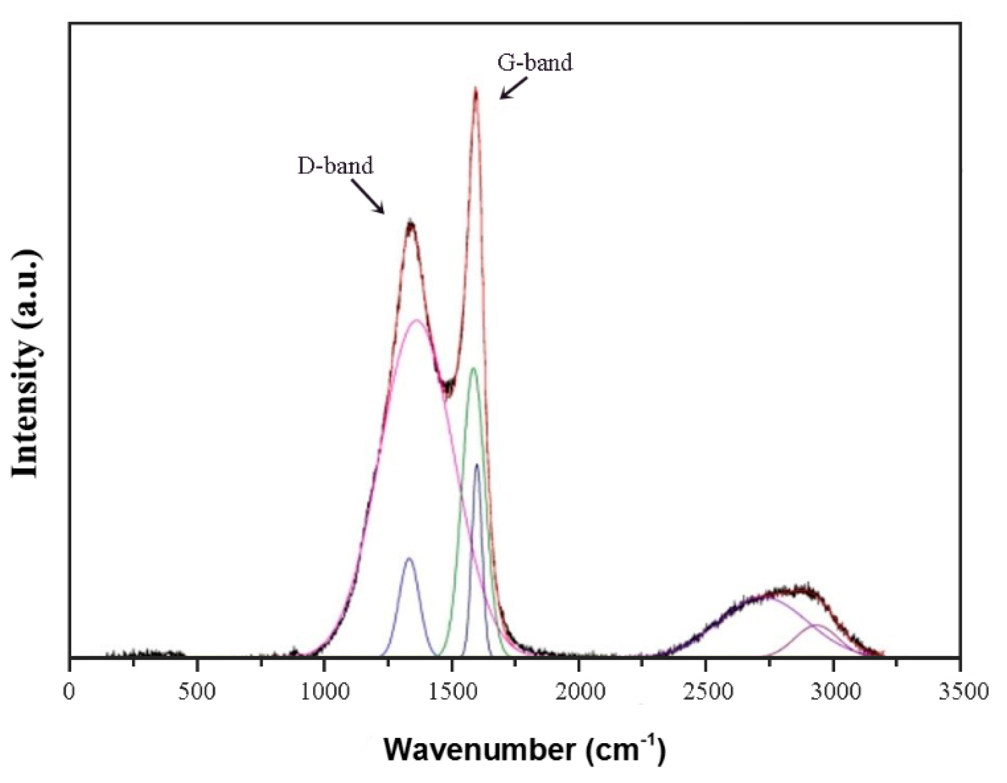
3.7. Raman Spectroscopy
3.8. Outcome Analysis
4. Conclusions
Author Contributions
Funding
Conflicts of Interest
Appendix A

| Blend | Stage 1 Temperature (°C) | Stage 2 Temperature (°C) | Extrusion Speed (% rpm) | Roller Distance (cm) |
|---|---|---|---|---|
| HDPE/SKL–LA | 220 | 230 | 100 | 23 |
| 226 | ||||
| 220 | 230 | 100 | 23 | |
| 235 | ||||
| 220 | 230 | 80 | 23 | |
| 100 | ||||
| 220 | 230 | 100 | 23 | |
| 28 | ||||
| 226 | 230 | 100 | 23 | |
| 235 | ||||
| 226 | 230 | 80 | 23 | |
| 100 | ||||
| 226 | 230 | 100 | 23 | |
| 28 |
| Blend | Stage 1 Temperature (°C) | Stage 2 Temperature (°C) | Extrusion Speed (% rpm) | Roller Distance (cm) |
|---|---|---|---|---|
| HDPE/SKL–PLA | 215 | 225 | 85 | 25 |
| 222 | ||||
| 215 | 225 | 85 | 25 | |
| 230 | ||||
| 215 | 225 | 65 | 25 | |
| 85 | ||||
| 215 | 225 | 85 | 25 | |
| 30 | ||||
| 222 | 225 | 85 | 25 | |
| 230 | ||||
| 222 | 225 | 65 | 25 | |
| 85 | ||||
| 222 | 225 | 85 | 25 | |
| 30 |
References
- Thunga, M.; Chen, K.; Grewell, D.; Kessler, M.R. Bio-renewable precursor fibers from lignin/polylactide blends for conversion to carbon fibers. Carbon 2014, 68, 159–166. [Google Scholar] [CrossRef]
- Mainka, H.; Täger, O.; Körner, E.; Hilfert, L.; Busse, S.; Edelmann, F.T.; Herrmann, A.S. Lignin—An alternative precursor for sustainable and cost-effective automotive carbon fiber. J. Mater. Res. Technol. 2015, 4, 283–296. [Google Scholar] [CrossRef]
- Maradur, S.P.; Kim, C.H.; Kim, S.Y.; Kim, B.H.; Kim, W.C.; Yang, K.S. Preparation of carbon fibers from a lignin copolymer with polyacrylonitrile. Synth. Met. 2012, 162, 453–459. [Google Scholar] [CrossRef]
- Ragauskas, A.J.; Beckham, G.T.; Biddy, M.J.; Chandra, R.; Chen, F.; Davis, M.F.; Davison, B.H.; Dixon, R.A.; Gilna, P.; Keller, M.; et al. Lignin valorization: Improving lignin processing in the biorefinery. Science 2014, 344, 1246843. [Google Scholar] [CrossRef]
- Naseem, A.; Tabasum, S.; Zia, K.M.; Zuber, M.; Ali, M.; Noreen, A. Lignin-derivatives based polymers, blends and composites: A review. Int. J. Biol. Macromol. 2016, 93 Pt A, 296–313. [Google Scholar] [CrossRef]
- Datta, J.; Parcheta, P.; Surówka, J. Softwood-lignin/natural rubber composites containing novel plasticizing agent: Preparation and characterization. Ind. Crop. Prod. 2017, 95, 675–685. [Google Scholar] [CrossRef]
- Ferdosian, F.; Yuan, Z.; Anderson, M.; Xu, C.C. Synthesis and characterization of hydrolysis lignin-based epoxy resins. Ind. Crop. Prod. 2016, 91, 295–301. [Google Scholar] [CrossRef]
- Simionescu, C.I.; Rusan, V.; Macoveanu, M.M.; Cazacu, G.; Lipsa, R.; Vasile, C.; Stoleriu, A.; Ioanid, A. Lignin/epoxy composites. Compos. Sci. Technol. 1993, 48, 317–323. [Google Scholar] [CrossRef]
- Zhou, Y.; Fan, M.; Chen, L. Interface and bonding mechanisms of plant fibre composites: An overview. Compos. B Eng. 2016, 101, 31–45. [Google Scholar] [CrossRef]
- Megiatto, J.D.; Silva, C.G.; Rosa, D.S.; Frollini, E. Sisal chemically modified with lignins: Correlation between fibers and phenolic composites properties. Polym. Degrad. Stab. 2008, 93, 1109–1121. [Google Scholar] [CrossRef]
- Lee, K.-Y.; Ho, K.K.C.; Schlufter, K.; Bismarck, A. Hierarchical composites reinforced with robust short sisal fibre preforms utilising bacterial cellulose as binder. Compos. Sci. Technol. 2012, 72, 1479–1486. [Google Scholar] [CrossRef]
- Migneault, S.; Koubaa, A.; Perré, P.; Riedl, B. Effects of wood fiber surface chemistry on strength of wood–plastic composites. Appl. Surf. Sci. 2015, 343, 11–18. [Google Scholar] [CrossRef]
- Alshaaer, M.; Mallouh, S.A.; Al-Kafawein, J.A.; Al-Faiyz, Y.; Fahmy, T.; Kallel, A.; Rocha, F. Fabrication, microstructural and mechanical characterization of Luffa Cylindrical Fibre—Reinforced geopolymer composite. Appl. Clay Sci. 2017, 143, 125–133. [Google Scholar] [CrossRef]
- Hervy, M.; Evangelisti, S.; Lettieri, P.; Lee, K.-Y. Life cycle assessment of nanocellulose-reinforced advanced fibre composites. Compos. Sci. Technol. 2015, 118, 154–162. [Google Scholar] [CrossRef]
- Ye, X.; Wang, H.; Zheng, K.; Wu, Z.; Zhou, H.; Tian, K.; Su, Z.; Tian, X. The interface designing and reinforced features of wood fiber/polypropylene composites: Wood fiber adopting nano-zinc-oxide-coating via ion assembly. Compos. Sci. Technol. 2016, 124, 1–9. [Google Scholar] [CrossRef]
- Soman, S.; Chacko, A.S.; Prasad, V.S. Semi-interpenetrating network composites of poly(lactic acid) with cis-9-octadecenylamine modified cellulose-nanofibers from Areca catechu husk. Compos. Sci. Technol. 2017, 141, 65–73. [Google Scholar] [CrossRef]
- Zhang, Y.; Gan, T.; Luo, Y.; Zhao, X.; Hu, H.; Huang, Z.; Huang, A.; Qin, X. A green and efficient method for preparing acetylated cassava stillage residue and the production of all-plant fibre composites. Compos. Sci. Technol. 2014, 102, 139–144. [Google Scholar] [CrossRef]
- Vaikhanski, L.; Lesko, J.J.; Nutt, S.R. Cellular polymer composites based on bi-component fibers. Compos. Sci. Technol. 2003, 63, 1403–1410. [Google Scholar] [CrossRef]
- Del Saz-Orozco, B.; Oliet, M.; Alonso, M.V.; Rojo, E.; Rodríguez, F. Formulation optimization of unreinforced and lignin nanoparticle-reinforced phenolic foams using an analysis of variance approach. Compos. Sci. Technol. 2012, 72, 667–674. [Google Scholar] [CrossRef]
- Wang, R.; Zhang, J.; Kang, H.; Zhang, L. Design, preparation and properties of bio-based elastomer composites aiming at engineering applications. Compos. Sci. Technol. 2016, 133, 136–156. [Google Scholar] [CrossRef]
- Meek, N.; Penumadu, D.; Hosseinaei, O.; Harper, D.; Young, S.; Rials, T. Synthesis and characterization of lignin carbon fiber and composites. Compos. Sci. Technol. 2016, 137, 60–68. [Google Scholar] [CrossRef]
- Wang, S.; Zhou, Z.; Xiang, H.; Chen, W.; Yin, E.; Chang, T.; Zhu, M. Reinforcement of lignin-based carbon fibers with functionalized carbon nanotubes. Compos. Sci. Technol. 2016, 128, 116–122. [Google Scholar] [CrossRef]
- Asp, L.E.; Greenhalgh, E.S. Structural power composites. Compos. Sci. Technol. 2014, 101, 41–61. [Google Scholar] [CrossRef]
- Laurichesse, S.; Avérous, L. Chemical modification of lignins: Towards biobased polymers. Prog. Polym. Sci. 2014, 39, 1266–1290. [Google Scholar] [CrossRef]
- McMurry, J. Carboxylic Acid Derivatives: Nucleophilic Acyl Substitution Reactions of Carboxylic Acids. In Organic Chemistry, 7th ed.; Brooks/Cole: Belmont, CA, USA, 2008; 21.3; pp. 794–800. [Google Scholar]
- McMurry, J. Carboxylic Acid Derivatives: Chemistry of Halide Acids. In Organic Chemistry, 7th ed.; Brooks/Cole: Belmont, CA, USA, 2008; 21.4; pp. 800–806. [Google Scholar]
- Goliszek, M.; Wiącek, A.E.; Wawrzkiewicz, M.; Sevastyanova, O.; Podkościelna, B. The impact of lignin addition on the properties of hybrid microspheres based on trimethoxyvinylsilane and divinylbenzene. Eur. Polym. J. 2019, 120, 109200. [Google Scholar] [CrossRef]
- Wang, X.; Zhai, M.; Wang, Z.; Dong, P.; Lv, W.; Liu, R. Carbonization and combustion characteristics of palm fiber. Fuel 2018, 227, 21–26. [Google Scholar] [CrossRef]
- Szycher, M. Szycher’s Handbook of Polyurethanes, 2nd ed.; CRC Press, Taylor & Francis Group: Boca Raton, FL, USA, 2013; pp. 87–134. [Google Scholar]
- Chauhan, M.; Gupta, M.; Singh, B.; Singh, A.K.; Gupta, V.K. Effect of functionalized lignin on the properties of lignin–isocyanate prepolymer blends and composites. Eur. Polym. J. 2014, 52, 32–43. [Google Scholar] [CrossRef]
- Dodda, J.M.; Bělský, P. Progress in designing poly(amide imide)s (PAI) in terms of chemical structure, preparation methods and processability. Eur. Polym. J. 2016, 84, 514–537. [Google Scholar] [CrossRef]
- Puszka, A.; Kultys, A. New thermoplastic polyurethane elastomers based on aliphatic diisocyanate. J. Therm. Anal. Calorim. 2016, 128, 407–416. [Google Scholar] [CrossRef]
- Ouyang, Q.; Wang, X.; Wang, X.; Huang, J.; Huang, X.; Chen, Y. Simultaneous DSC/TG analysis on the thermal behavior of PAN polymers prepared by aqueous free-radical polymerization. Polym. Degrad. Stab. 2016, 130, 320–327. [Google Scholar] [CrossRef]
- Tripathi, A.K.; Tsavalas, J.G.; Sundberg, D.C. Quantitative measurements of the extent of phase separation during and after polymerization in polymer composites using DSC. Thermochim. Acta 2013, 568, 20–30. [Google Scholar] [CrossRef]
- Schawe, J.E.K. Remarks regarding the determination of the initial crystallinity by temperature modulated DSC. Thermochim. Acta 2017, 657, 151–155. [Google Scholar] [CrossRef]
- Dumas, J.P.; Gibout, S.; Cézac, P.; Franquet, E. New theoretical determination of latent heats from DSC curves. Thermochim. Acta 2018, 670, 92–106. [Google Scholar] [CrossRef]
- Klásek, A.; Rege, D.V. Reaction of 4-hydroxy-2-quinolones with thionyl chloride—Preparation of new spiro-benzo[1,3]oxathioles and their transformations. Tetrahedron 2013, 69, 492–499. [Google Scholar] [CrossRef]
- Merchant, J.R.; Rege, D.V. Reaction of thionyl chloride with flavone. Tetrahedron Lett. 1969, 10, 3589–3591. [Google Scholar] [CrossRef]
- Chern, Y.-T.; Huang, C.-M. Synthesis and characterization of new polyesters derived from 1,6- or 4,9-diamantanedicarboxylic acyl chlorides with aryl ether diols. Polymer 1998, 39, 2325–2329. [Google Scholar] [CrossRef]
- Sutter, P.; Weis, C.D. The chlorination of 1,4-dihydroxyanthraquinone with thionyl chloride. Dye. Pigment. 1985, 6, 435–443. [Google Scholar] [CrossRef]
- Freeman, J.H.; Smith, M.L. The preparation of anhydrous inorganic chlorides by dehydration with thionyl chloride. J. Inorg. Nucl. Chem. 1958, 7, 224–227. [Google Scholar] [CrossRef]
- Zhao, J.; Xiuwen, W.; Hu, J.; Liu, Q.; Shen, D.; Xiao, R. Thermal degradation of softwood lignin and hardwood lignin by TG-FTIR and Py-GC/MS. Polym. Degrad. Stab. 2014, 108, 133–138. [Google Scholar] [CrossRef]
- Jin, W.; Shen, D.; Liu, Q.; Xiao, R. Evaluation of the co-pyrolysis of lignin with plastic polymers by TG-FTIR and Py-GC/MS. Polym. Degrad. Stab. 2016, 133, 65–74. [Google Scholar] [CrossRef]
- Ravindar Reddy, M.; Subrahmanyam, A.R.; Maheshwar Reddy, M.; Siva Kumar, J.; Kamalaker, V.; Jaipal Reddy, M. X-RD, SEM, FT-IR, DSC Studies of Polymer Blend Films of PMMA and PEO. Mater. Today Proc. 2016, 3, 3713–3718. [Google Scholar] [CrossRef]
- Soulis, S.; Anagnou, S.; Milioni, E.; Mpalias, C.; Kartsonakis, I.A.; Kanellopoulou, I.; Markakis, V.; Koumoulos, E.P.; Kontou, E.; Charitidis, C.A. Strategies towards Novel Carbon Fiber Precursors: The Research Results on the Synthesis of PAN Copolymers via AGET ATRP and on Lignin as a Precursor. NanoWorld J. 2015, 1, 88–94. [Google Scholar] [CrossRef][Green Version]
- Abrishambaf, A.; Pimentel, M.; Nunes, S. Influence of fibre orientation on the tensile behaviour of ultra-high performance fibre reinforced cementitious composites. Cem. Concr. Res. 2017, 97, 28–40. [Google Scholar] [CrossRef]
- Jang, S.Y.; Ko, S.; Jeon, Y.P.; Choi, J.; Kang, N.; Kim, H.C.; Joh, H.-I.; Lee, S. Evaluating the stabilization of isotropic pitch fibers for optimal tensile properties of carbon fibers. J. Ind. Eng. Chem. 2017, 45, 316–322. [Google Scholar] [CrossRef]
- Torres, J.P.; Vandi, L.J.; Veidt, M.; Heiztmann, M.T. Statistical data for the tensile properties of natural fibre composites. Data Brief 2017, 12, 222–226. [Google Scholar] [CrossRef]
- Zhong, Y.; Bian, W. Analysis of the tensile moduli affected by microstructures among seven types of carbon fibers. Compos. B Eng. 2017, 110, 178–184. [Google Scholar] [CrossRef]
- Bie, B.X.; Huang, J.Y.; Fan, D.; Sun, T.; Fezzaa, K.; Xiao, X.H.; Qi, M.L.; Luo, S.N. Orientation-dependent tensile deformation and damage of a T700 carbon fiber/epoxy composite: A synchrotron-based study. Carbon 2017, 121, 127–133. [Google Scholar] [CrossRef]
- Borodulina, S.; Motamedian, H.R.; Kulachenko, A. Effect of fiber and bond strength variations on the tensile stiffness and strength of fiber networks. Int. J. Solids Struct. 2016, 154, 19–32. [Google Scholar] [CrossRef]
- Wan, Y.; Straumit, I.; Takahashi, J.; Lomov, S.V. Micro-CT analysis of internal geometry of chopped carbon fiber tapes reinforced thermoplastics. Compos. A Appl. Sci. Manuf. 2016, 91, 211–221. [Google Scholar] [CrossRef]
- Ferguson, J.C.; Panerai, F.; Lachaud, J.; Martin, A.; Bailey, S.C.C.; Mansour, N.N. Modeling the oxidation of low-density carbon fiber material based on micro-tomography. Carbon 2016, 96, 57–65. [Google Scholar] [CrossRef]
- Liu, J.; Li, C.; Liu, J.; Cui, G.; Yang, Z. Study on 3D spatial distribution of steel fibers in fiber reinforced cementitious composites through micro-CT technique. Constr. Build. Mater. 2013, 48, 656–661. [Google Scholar] [CrossRef]
- Sencu, R.M.; Yang, Z.; Wang, Y.C.; Withers, P.J.; Rau, C.; Parson, A.; Soutis, C. Generation of micro-scale finite element models from synchrotron X-ray CT images for multidirectional carbon fibre reinforced composites. Compos. A Appl. Sci. Manuf. 2016, 91, 85–95. [Google Scholar] [CrossRef]
- Cosmi, F.; Bernasconi, A. Micro-CT investigation on fatigue damage evolution in short fibre reinforced polymers. Compos. Sci. Technol. 2013, 79, 70–76. [Google Scholar] [CrossRef]
- Ning, Z.; Liu, R.; Elhajjar, R.F.; Wang, F. Micro-modeling of thermal properties in carbon fibers reinforced polymer composites with fiber breaks or delamination. Compos. B Eng. 2017, 114, 247–255. [Google Scholar] [CrossRef]
- Headrick, R.J.; Trafford, M.A.; Taylor, L.W.; Dewey, O.S.; Wincheski, R.A.; Pasquali, M. Electrical and acoustic vibroscopic measurements for determining carbon nanotube fiber linear density. Carbon 2019, 144, 417–422. [Google Scholar] [CrossRef]
- Putignano, C.; Menga, N.; Afferrante, L.; Carbone, G. Viscoelasticity induces anisotropy in contacts of rough solids. J. Mech. Phys. Solids 2019, 129, 147–159. [Google Scholar] [CrossRef]
- Xia, Y.; Cai, J.; Perfect, E.; Wei, W.; Zhang, Q.; Meng, Q. Fractal dimension, lacunarity and succolarity analyses on CT images of reservoir rocks for permeability prediction. J. Hydrol. 2019, 579, 124198. [Google Scholar] [CrossRef]
- Liu, X.; Zhu, C.; Guo, J.; Liu, Q.; Dong, H.; Gu, Y.; Liu, R.; Zhao, N.; Zhang, Z.; Xu, J. Nanoscale dynamic mechanical imaging of the skin–core difference: From PAN precursors to carbon fibers. Mater. Lett. 2014, 128, 417–420. [Google Scholar] [CrossRef]
- Long, D.A. Infrared and Raman characteristic group frequencies. Tables and chartsGeorge Socrates John Wiley and Sons, Ltd, Chichester, Third Edition, 2001, Price £135. J. Raman Spectrosc. 2004, 35, 905. [Google Scholar] [CrossRef]
- Musiol, P.; Szatkowski, P.; Gubernat, M.; Weselucha-Birczynska, A.; Blazewicz, S. Comparative study of the structure and microstructure of PAN-based nano- and micro-carbon fibers. Ceram. Int. 2016, 42, 11603–11610. [Google Scholar] [CrossRef]
- Jin, S.; Guo, C.; Lu, Y.; Zhang, R.; Wang, Z.; Jin, M. Comparison of microwave and conventional heating methods in carbonization of polyacrylonitrile-based stabilized fibers at different temperature measured by an in-situ process temperature control ring. Polym. Degrad. Stab. 2017, 140, 32–41. [Google Scholar] [CrossRef]
- Park, O.-K.; Lee, S.; Joh, H.-I.; Kim, J.K.; Kang, P.-H.; Lee, J.H.; Ku, B.-C. Effect of functional groups of carbon nanotubes on the cyclization mechanism of polyacrylonitrile (PAN). Polymer 2012, 53, 2168–2174. [Google Scholar] [CrossRef]
- Batchelor, B.L.; Mahmood, S.F.; Jung, M.; Shin, H.; Kulikov, O.V.; Voit, W.; Novak, B.M.; Yang, D.J. Plasticization for melt viscosity reduction of melt processable carbon fiber precursor. Carbon 2016, 98, 681–688. [Google Scholar] [CrossRef]
- Berrueco, C.; Álvarez, P.; Díez, N.; Granda, M.; Menéndez, R.; Blanco, C.; Santamaria, R.; Millan, M. Characterisation and feasibility as carbon fibre precursors of isotropic pitches derived from anthracene oil. Fuel 2012, 101, 9–15. [Google Scholar] [CrossRef]
- Li, X.; Zhu, X.-Q.; Okuda, K.; Zhang, Z.; Ashida, R.; Yao, H.; Miura, K. Preparation of carbon fibers from low-molecular-weight compounds obtained from low-rank coal and biomass by solvent extraction. New Carbon Mater. 2017, 32, 41–47. [Google Scholar] [CrossRef]
- Şahin, K.; Fasanella, N.A.; Chasiotis, I.; Lyons, K.M.; Newcomb, B.A.; Kamath, M.G.; Chae, H.G.; Kumar, S. High strength micron size carbon fibers from polyacrylonitrile–carbon nanotube precursors. Carbon 2014, 77, 442–453. [Google Scholar] [CrossRef]
- Spörl, J.M.; Ota, A.; Son, S.; Massonne, K.; Hermanutz, F.; Buchmeiser, M.R. Carbon fibers prepared from ionic liquid-derived cellulose precursors. Mater. Today Commun. 2016, 7, 1–10. [Google Scholar] [CrossRef]
- Guo, T.; Xia, Q.; Shao, Y.; Liu, X.; Wang, Y. Direct deoxygenation of lignin model compounds into aromatic hydrocarbons through hydrogen transfer reaction. Appl. Catal. A Gen. 2017, 547, 30–36. [Google Scholar] [CrossRef]


| Blend | Stage 1 Temperature (°C) | Stage 2 Temperature (°C) | Extrusion Speed (% rpm) | Roller Distance (cm) |
|---|---|---|---|---|
| HDPE/SKL–LA | 226 | 230 | 100 | 23 |
| HDPE/SKL–PLA | 222 | 225 | 85 | 25 |
| Sample | 150 °C, 1 h | 220 °C, 3 h | 300 °C, 10 min | Proceeded to Carbonization | Successful Carbonization |
|---|---|---|---|---|---|
| HDPE/SKL–LA | sustained | sustained | sustained | Yes | need for optimization |
| HDPE/SKL–PLA | sustained (fiber shrinkage) | sustained | sustained | Yes | Yes |
| Sample | Min. Diameter (μm) | Max. Diameter (μm) | Average Diameter (μm) |
|---|---|---|---|
| HDPE/SKL–LA | 158 | 165 | 161.5 |
| HDPE/SKL–PLA (precursor) | 155 | 164 | 159.5 |
| HDPE/SKL–PLA (carbon fiber) | 168.5 | 170.1 | 169.3 |
| Sample | Element | wt.% |
|---|---|---|
| C | 57.60 | |
| HDPE/SKL–PLA (precursor) | O | 41.53 |
| Cl | 0.87 | |
| C | 87.89 | |
| HDPE/SKL–PLA (carbon fiber) | O | 11.60 |
| Cl | 0.51 |
| Sample | Onset Temperature of Thermal Degradation (°C) | Peak Temperature of Thermal Degradation (°C) | End Temperature of Thermal Degradation (°C) | Mass Change (wt.%) |
|---|---|---|---|---|
| PLCl | 284.9 | 320.8 | 399.3 | 95 |
| SKL–LA | 205.1 | 277.9 | 740.0 | 75 |
| SKL–PLA | 236.1 | 285.7 | 781.8 | 69 |
| HDPE/SKL–PLA (carbon fiber) | 625.0 | 725 | 800.0 | 15 |
| Wavenumber (cm−1) | Type of Bond Vibration |
|---|---|
| 3294 | –COOH (PLA) |
| 2847 | –COOH (PLA) |
| 1750 | C=O (both PLA and PLCl) |
| 1640 | asymmetric CO2− stretching vibration (PLA) |
| 1558 | asymmetric CO2− stretching vibration (PLA) |
| 1453 | C–H (both PLA and PLCl) |
| 1185 | C–O (both PLA and PLCl) |
| 1080 | C–O (both PLA and PLCl) |
| 750 | C–H (both PLA and PLCl) |
| Wavenumber (cm−1) | Type of Bond |
|---|---|
| 3500 | O–H (both SKL–LA and SKL–PLA) |
| 2900 | C–H stretch |
| 1750 | C=O (both SKL–LA and SKL–PLA) |
| 1600 | aromatic lignin rings (conjugated structure) |
| 1500 | aromatic lignin rings |
| 1410 | aromatic lignin rings |
| 1150–1185 | C–O (both SKL–LA and SKL–PLA) |
| 750 | C–H bend (both SKL–LA and SKL–PLA) |
| Parameters | HDPE/SKL–PLA Carbonized |
|---|---|
| Object Surface Density (mm−1) | 17.19 |
| Structure Linear Density (mm−1) | 12.68 |
| Degree of Anisotropy | 1.599 |
| Fractal Dimension | 2.600 |
| Total Porosity (%) | 1.995 |
© 2019 by the authors. Licensee MDPI, Basel, Switzerland. This article is an open access article distributed under the terms and conditions of the Creative Commons Attribution (CC BY) license (http://creativecommons.org/licenses/by/4.0/).
Share and Cite
Goulis, P.; Kartsonakis, I.A.; Konstantopoulos, G.; Charitidis, C.A. Synthesis and Processing of Melt Spun Materials from Esterified Lignin with Lactic Acid. Appl. Sci. 2019, 9, 5361. https://doi.org/10.3390/app9245361
Goulis P, Kartsonakis IA, Konstantopoulos G, Charitidis CA. Synthesis and Processing of Melt Spun Materials from Esterified Lignin with Lactic Acid. Applied Sciences. 2019; 9(24):5361. https://doi.org/10.3390/app9245361
Chicago/Turabian StyleGoulis, Panagiotis, Ioannis A. Kartsonakis, George Konstantopoulos, and Costas A. Charitidis. 2019. "Synthesis and Processing of Melt Spun Materials from Esterified Lignin with Lactic Acid" Applied Sciences 9, no. 24: 5361. https://doi.org/10.3390/app9245361
APA StyleGoulis, P., Kartsonakis, I. A., Konstantopoulos, G., & Charitidis, C. A. (2019). Synthesis and Processing of Melt Spun Materials from Esterified Lignin with Lactic Acid. Applied Sciences, 9(24), 5361. https://doi.org/10.3390/app9245361