Abstract
Nowadays, piezoelectric actuators are widely used, but are rarely applied in high overload environments due to th difficulty implementing them. Traveling wave rotary ultrasonic motors (TRUMs) have the characteristics of variable structure and are insensitive to overload, endowing them with the potential ability of high overload resistance. In this study, four TRUMs with different rotor structures are designed to work under the high-impact acceleration of 10,000 g through modifying the rotors with a designed slotted disc spring. The dynamics model is established, the impact process is simulated, and the results are analyzed successively. The high-impact test, deformation measurement and performance test of the motors are carried out to verify the modification. The results show that performance of the TRUMs with a disc spring declines much less than those without a disc spring after the high-impact test. The TRUM-4 with the modified rotor and disc spring has the best performance, the speed of which decreased only 1.6% at the torque of 0.15 N m, and it is considered to be capable of withstanding the high acceleration of 10,000 g. This work is significance for guiding the ultrasonic motors’ optimization to expand their application in high-overload environments.
1. Introduction
Piezoelectric actuators, which have the advantages of compact structure, quick response, good electromagnetic compatibility, and high precision, have been widely used in the field of micromechanical systems, aerospace mechanisms, micro-robots and high-precision machines [1,2,3,4]. However, due to their particularity and complexity, the application of piezoelectric actuators in high-overload environments is limited. A traveling-wave rotary ultrasonic motor (TRUM), one of the most typical ultrasonic motors or piezoelectric actuators [5,6], has the characteristics of variable structure, flexible selection of the working modes, and insensitivity to the overload [7]. All these features give the TRUM the potential ability of high overload resistance and design advantages, making it possible to realize the application of the TRUM in the high-overload environment [8]. However, there are only a few research reports about the high-overload field of TRUMs. Ren et al. established a finite element model of the TRUM under high acceleration of 10,000 g using LS-DYNA (a nonlinear finite element solver) and analyzed the stress distribution and failures of TRUM [7]. Sun et al. established a theoretical model about dynamic response of TRUM in shock environment based on theoretical rigid plasticity model, proposed the concept of TRUM-based acceleration sensor, and conducted experimental validation [9,10]. Xu et al. analyzed the response characteristics of a TRUM under a high-overload environment and mentioned that the wave spring and stainless steel gasket were effective for the anti-overloaded actuator [11], but the process of establishing the impact dynamics model and the performance of the TRUM was not described in detail. All the above research theoretically analyzed the feasibility of TRUM application under high overload environments. However, the influence of the high overload on the performance of the TRUM, which is vital for its application, is rarely reported. There is still a lack of studies which could be beneficial to the reliability prediction of TRUM and to its optimal design to improve the ability of high overload resistance.
For the above purposes, based on the PMR40 ultrasonic motor (a kind of TRUM made by NUAA Super Control Technology Co. Ltd., Nanjing, China), the rotor structure is optimized, four motors are designed, and the impact dynamics model of the TRUM with high acceleration of 10,000 g is established using the finite element (FE) software Automatic Dynamic Incremental Non-Linear Analysis (ADINA). Force situations during the impact of the main parts and contact surfaces of the TRUMs are analyzed, and motors’ performances before and after the impact are compared in experiments.
Finally, a TRUM structure with the strongest anti-overload capability and the best reliability is obtained. The actual high-overload test will cause large loss to the motors and high cost. By establishing the impact dynamics model, the impact process is simulated, the results are analyzed, and the motor structure is optimized. This work is of important guiding significance to the design and application of ultrasonic motor in the high-overload environment.
2. Structure Improvement Design of Traveling-Wave Rotary Ultrasonic Motor (TRUM) in High-Overload Environments
2.1. Working Principle of the TRUM
Figure 1 shows the structure of the PMR40 motor. The stator, together with the ceramic piece pasted to its surface, are bolted to the base; the rotor has a vibration-damping sheet on one side and a friction plate on the other side; one end of the shaft is bolted to the rotor base and the other end is designed with a thread connected to the base through a bearing. The lock nut is tightly connected to the shaft end thread to press the base, the stator and the rotor, thereby generating pre-pressure between the stator and the rotor. The vibration on the surface of the stator, which is excited by the piezoelectric ceramic, is converted into rotation of the rotor by the frictional force between the stator and rotor contact interface.
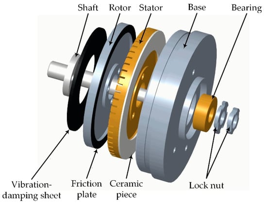
Figure 1.
Structure of the PMR40 ultrasonic motor.
In our previous research, a high overload experiment of 10,000 g impact acceleration was performed on the PMR40 motor. The results showed that the rotor and stator were deformed, the ceramic was broken and the motor failed to work. These results can only demonstrate the state of the motor after impact, but cannot explain the mechanism of the influence of the high-impact process on the motor. Meanwhile, the high overload test is very expensive and difficult to realize. Therefore, it is more economical and effective to establish the impact dynamics model to guide the design of the motor structure of high-overload resistance.
To reduce the maximum stress or deformation of the stator and rotor during the high-impact process so as to reduce the contact surface variation, the weak rotor structure is improved based on the structure of the PMR40. A disc spring is designed to modify the rotor and four new TRUMs are designed. The impact dynamics simulation model of the TRUM is established to analyze dynamic response of each key part and the results are finally verified by experiments.
2.2. Design of Disc Spring for TRUM
The disc spring has strong buffer absorption capacity and can withstand large loads with small deformation [12,13,14], so as a buffering component it is very suitable for TRUM with very limited axial space working under high-overload conditions. In particular, the disc spring is a non-linear spring. During the loading process, a working area with zero stiffness will occur in the force characteristic of the disc spring, where, the load force keeps almost unchanged but the spring still deforms. This is called the “quasi-zero stiffness” characteristic. [15,16]. Considering this, the disc spring as a buffering element is used to protect the rotor in the motor and the contact interface.
The disc springs for TRUMs should be specially designed. Here, the slotted disc spring is selected, which is usually applied in situations where the axial dimension is limited and the outer diameter is large. Based on the experimental experience, the best performance of the PMR40 motor is generally obtained at the pre-loading force of 135 ± 5 N. Therefore, when designing a slotted disc spring, it is desirable that the zero-stiffness section occurs at the load of about 135 N and the span of it is expected to be longer, which plays an important role in stabilizing the TRUM’s pre-pressure and performance. The calculation formula for load P of slotted disc spring [16] is shown in Equation (1).
where E is the Young’s modulus of the slotted conical disc spring; µ is the Poisson’s ratio; δ is the thickness; ƒ is the deformation; H is the cone height; D is the outer diameter; Dm is the slotted bottom diameter; K1 is the constant, which can be calculated by Equation (2).
According to references [17,18,19], when, the designed slotted disc spring will have the force characteristic of “quasi-zero stiffness”. Figure 2 illustrates the geometry of the designed slotted disc spring and the structural parameters are summarized in Table 1. Figure 3 shows the displacement-load mechanical characteristic of the designed slotted disc spring.
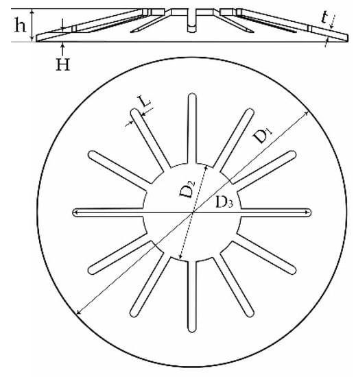
Figure 2.
Slotted disc spring designed for traveling-wave rotary ultrasonic motor (TRUM).

Table 1.
The structural parameters of the disc spring.
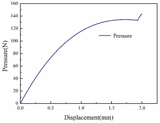
Figure 3.
Mechanical characteristic curve of the disc spring.
From Figure 3, it can be seen that the section in which the disc spring deformation is 1.4–1.9 mm can be regarded as the “quasi-zero stiffness” section. In this section, deformation of the disc spring increases, but the load is keeping at about 135 N. When the deformation of the disc spring exceeds 1.9 mm, the lower surface of the disc spring will come into contact with the fixed surface of the test platform. As the load continues to increase, the contact area becomes larger and larger, thus, the mechanical characteristic of the disc spring changes and the stiffness increases instantly. When the disc spring is flattened, the lower contact surface of the disc spring is completely in contact with the test platform’s surface, and then the stiffness reaches maximum. The designed disc spring is used to improve the structure of the rotor as a rigid rotor system composed of an upper rotor, a disc spring and a lower rotor. During assembling, the disc spring is compressed to the initial position of the zero-stiffness section, where the deformation is 1.4 mm and the corresponding pre-loading force is 135 N.
2.3. New TRUM Designs
Based on the rotor of PMR40 (original rotor), considering the influence of different rotor stiffness on motor performance, the rotor modified schemes are proposed and four TRUMs with different rotor structures are designed as shown in Figure 4.
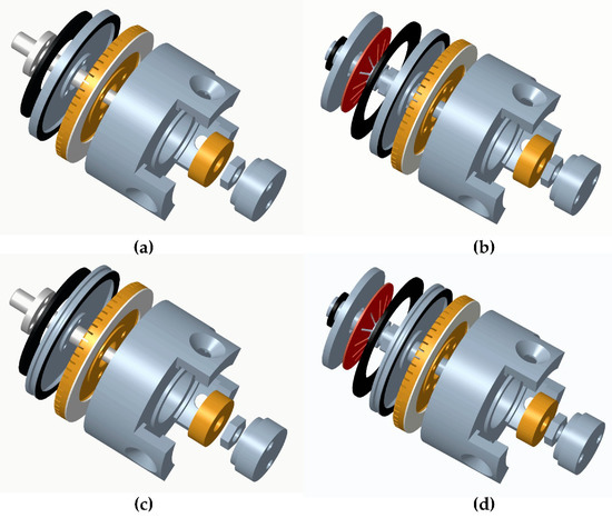
Figure 4.
Structure of the TRUMs: (a) TRUM-1; (b) TRUM-2; (c) TRUM-3; (d) TRUM-4.
The four TRUMs are defined as follows:
- The TRUM with the original rotor and new base is labeled as TRUM-1, as shown in Figure 4a.
- The TRUM with the original rotor and the disc spring disposed above it as a cushioning element is marked as TRUM-2, as shown in Figure 4b.
- Based on the original rotor, thickness of the rotor’s web is reduced and an “I-Beam”-shaped ring groove is cut at the edge of the rotor. The rotor with such structure characteristic is called the modified rotor which is less rigid and more flexible than the original rotor. The TRUM with the modified rotor is labeled as TRUM-3, as shown in Figure 4c.
- The TRUM with the modified rotor and disc spring disposed above it is marked as TRUM-4, as shown in Figure 4d.
3. Modeling and Analysis
In this research, the TRUM working under high impact acceleration of 10,000 g is simulated by the commercial FE software ADINA. The impact dynamics model is established and the results are analyzed. ADINA is particular suitable for FE simulation calculation of complex structures, and especially good for solving non-linear numerical calculation problems of a contact mechanism [20,21]. Therefore, it is very appropriate for simulating the TRUM that involves many complicated contact problems. The simulation process based on the international system of units is divided into the following aspects.
3.1. Mesh Generation
Considering the structural characteristics of the motor and the complexity of the calculation, the structure is simplified. Meanwhile, in order to improve the accuracy of the calculation, the second order hexahedron element is mainly used in the model finite element mesh. Figure 5 shows the FE mesh of the above four motor models.
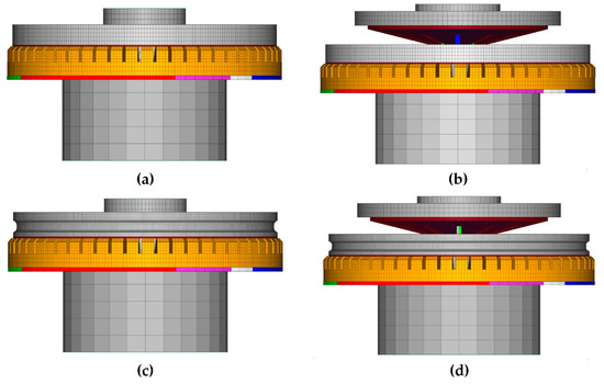
Figure 5.
Finite element (FE) model mesh of the TRUMs: (a) TRUM-1; (b) TRUM-2; (c) TRUM-3; (d) TRUM-4.
3.2. Material Setting
The stator of the TRUM is made of phosphor bronze. The shaft and rotor are made of steel-45 and aluminum, respectively. The friction plate is made of polytetrafluoroethylene (PTFE) which is an orthotropic material. These materials are all set as elastoplastic materials. The disc spring is made of 60Si2Mn material which is elastic material. The details are displayed in Table 2. In addition, material of the piezoelectric ceramic bonded to the stator is PZT-8H, whose material parameters can refer to ADINA’s primer [22].

Table 2.
Constants of the utilized materials in this study.
3.3. Loading and Boundary Condition
According to the working principle and structural characteristics of the TRUMs, meshes of the rotor and the friction plate are glued together to restrain any relative movement between them. The same treatment is applied between the stator and the ceramic piece, the stator and the base respectively. The upper surface of the stator is in contact with the lower surface of the friction plate adhered to the rotor, so there is a contact pair [23] between them, as shown in the Figure 6. The red part is the stator surface and the black part is the friction surface. Moreover, there are other three contact pairs between the spring and the rotor, the spring and the shaft and the rotor and the shaft.
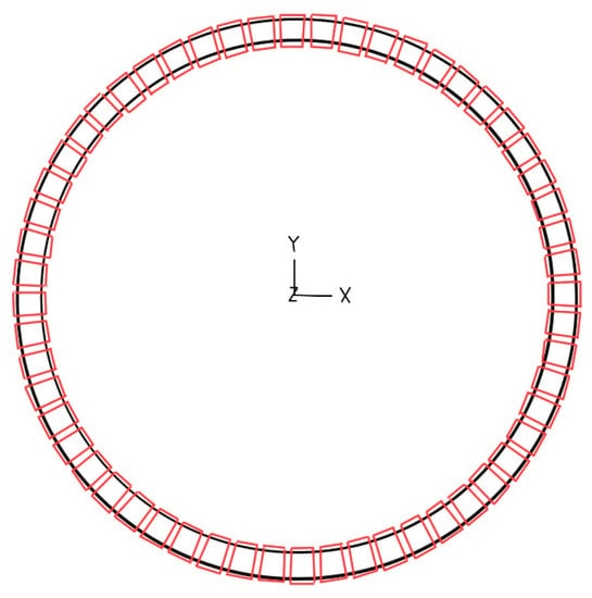
Figure 6.
Contact pair between the stator and friction plate.
The bolt function in the ADINA is used to preload the pre-pressure of the motor model. All the rotation and movement of the motor base are constrained except the Z direction movement, which means that the motor can only move along the axial direction. A rigid point connected to the motor base is for acceleration loading. The direction of acceleration is set opposite to the Z direction as shown by the arrow in the Figure 7a. Model constraints and load settings are shown in Figure 7a,b.
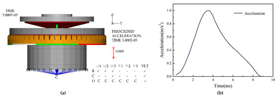
Figure 7.
Constraints and load settings of the model: (a) constraints setting; (b) the high-impact acceleration loading curve.
3.4. Simulation Results Analysis
The simulation results of the impact dynamics of the TRUMs mainly include the stress of the stator, rotor and friction plate, and the force on the contact surface between the stator and rotor. For better analysis of the simulation results, the four motors are divided into two groups for comparison. The TRUM-1 and TRUM-2 are set as group 1, and the TRUM-3 and TRUM-4 are set as group 2.
3.4.1. Comparison of Rotor Stress
Figure 8 shows the stress cloud diagrams of rotors in the motors at the moment of maximum stress occurs. It can be seen that during the high-impact process, the maximum stress of rotor of the TRUM-1 reaches 481.4 MPa, which exceeds the yield strength of the rotor material (325 MPa), so the rotor will be plastically deformed and operation of the motor will be badly influenced. For the TRUM-2, however, the maximum stress value of the rotor is 287.0 MPa, which does not exceed the yield strength of the rotor material. The rotor deforms elastically. When the impact acceleration is removed, the rotor will return to its original shape without affecting the structure of the motor. Similarly, comparing the motors in group 2, it is shown that the maximum stress values of the rotors in TRUM-3 and TRUM-4 are 432.6 MPa and 259.3 MPa respectively, which means that there is plastic deformation in TRUM-3’s rotor, but not in TRUM-4’s rotor. Thus, it can be concluded that the disc spring does have a good buffering effect during the high impact to the motor and the rotor is protected. It can also be observed from the cloud diagrams that during the impact process, the stress is concentrated at the root of the middle boss of the rotor where the maximum stress occurs. Therefore, the improved design of the rotor can be considered from the perspective of reducing the stress concentration at the junction of the boss and web.
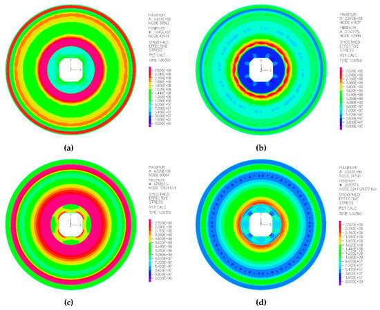
Figure 8.
Stress-cloud diagrams of the rotors at the moment that maximum stress occurs: (a) TRUM-1; (b) TRUM-2; (c) TRUM-3; (d) TRUM-4.
3.4.2. Comparison of Stator Stress
Figure 9 illustrates the stress cloud diagrams of the stators in the motors at the moment that maximum stress occurs.
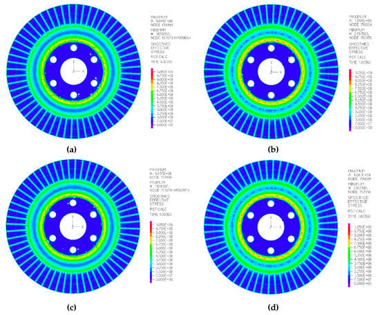
Figure 9.
Stress cloud diagrams of the stators at the moment that maximum stress occurs: (a) TRUM-1; (b) TRUM-2; (c) TRUM-3; (d) TRUM-4.
It is shown that the maximum stress of the four motors stators are 984.9 MPa (TRUM-1), 1059.9 MPa (TRUM-2), 993.7 MPa (TRUM-3), and 1061 MPa (TRUM-4), respectively. They all exceed the stator material yield strength (404 MPa), so the stator will be plastically deformed. Comparing the data, it can be found that the maximum stress of the stator of motors with the disc spring are slightly larger than that without disc spring which means that the stator plastic deformation of motors without the disc spring will be larger than that with disc spring. However, these maximum stress values are very close, indicating that the addition of a disc spring to the structure does not have a significant effect on the stator. Meanwhile, it can be seen through the cloud diagram that during the impact process, the maximum stress of the stator occurs at the web of the intermediate base root to the stator tooth root. Therefore, improving the structure of the stator from reducing the stress concentration at the web can be considered.
3.4.3. Comparison of Friction Plates Stress
In the same way, stresses of the four motor friction plates are obtained from the stress cloud diagrams, respectively, 4.66 MPa (TRUM-1), 3.54 MPa (TRUM-2), 6.06 MPa (TRUM-3) and 3.84 MPa (TRUM-4). None of them exceeds the yield strength of the friction material (55 MPa). However, it can be found that the maximum stress of the friction plate of motors with the disc spring is smaller than those without the disc spring, further verifying the protection of the disc spring to the parts in the TRUMs.
3.4.4. Analysis of Contact Surface Pressure
Research of the contact surface pressure has always been a difficult problem in the field of ultrasonic motors. The software ADINA is especially good at contact surface non-linear analysis. The impact dynamics model can be used to extract the contact surface force of each motor subjected to the impact process, as shown in Figure 10.
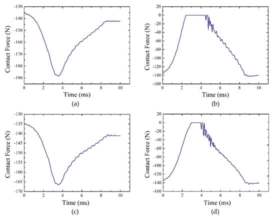
Figure 10.
Contact surface force change during the impact process: (a) TRUM-1; (b) TRUM-2; (c) TRUM-3; (d) TRUM-4.
It is revealed from the Figure 10a,b that during the impact process, the contact force of TRUM-1 gradually increases from the initial 135 N to the maximum 185 N, then becomes smaller, and the final pressure is about 140 N. Contact surface force variation trend of TRUM-3 is consistent with TRUM-1, but the maximum value is 167 N. For TRUM-2 and TRUM-4, the contact surface pressure gradually decreases from the initial pre-pressure 135 N to 0 N, is maintained for a certain period of time, then continues to increase, and finally, the contact force is around 140 N. This means that in the process of impacting, there is a short period of time in which the stator and rotor contact surfaces are separated, and then the contact is resumed. The process time is extremely short, and there is relative vibration between the stator and the rotor. The duration time of TRUM-4 contact surface pressure of 0 N is shorter than that of TRUM-2 during the impact process as shown in Figure 10b–d. This phenomenon is caused by the difference in the structure of the two motors, mainly, the differences of the rotors’ structure. The rotor web of TRUM-4 is thinner and more elastic than TRUM-2’s. When the stator and rotor contact surfaces are instantaneously separated due to the impact force, the rotor of TRUM-4 with better elasticity can recover to contact with the stator more quickly than rotor in TRUM-2.
4. Experiment and Analysis
Four sets of TRUMs are machined with the structures mentioned above. They are subjected to a high-impact test with the acceleration of 10,000 g. The deformation measurement experiment and mechanical performance test are carried out as well. Figure 11 shows the four physical motors; from left to right, TRUM-1, TRUM-2, TRUM-3 and TRUM-4.
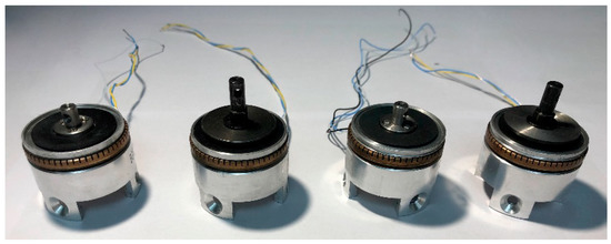
Figure 11.
The four physical TRUMs.
4.1. High-Impact Test of the TRUMs
The high-impact test with acceleration of 10,000 g to the TRUMs is done by using the pneumatic impact test platform (model: SM-110-MP) produced by Transmission Science and Technology Co., Limited, Huntsville, AL, USA. The maximum acceleration that can be achieved by this set is 30,000 g. The pulse width is 0.012–100 ms. As shown in Figure 12, the impact test bench system mainly includes: an impact test bench, an air compressor, a gas storage tank, a filter and a control panel, etc. In addition, there is an electromagnetic switch, a piston and cylinder, an acceleration sensor, a piston and external mounting in the internal design which are connected to the mounting platform.
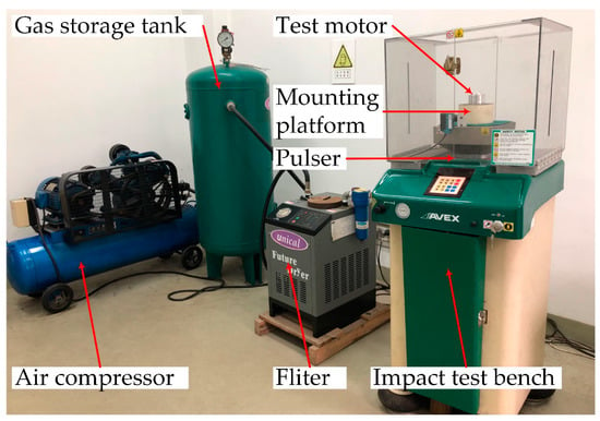
Figure 12.
SM-110-MP impact-test bench system.
Before the impact test, the motor is fixed on the mounting platform, and the maximum acceleration of 10,000 g is set through the control panel on the impact-test platform. The acceleration is measured by an acceleration sensor inside the test platform and feedback control is designed to ensure the acceleration value. During the impact test, compressed air is introduced to the underside of the piston, raising the platform to a pre-selected height. Once this is achieved, the brake is activated, the lift air is exhausted and compressed air is introduced into the other side of the piston. When the required inflation pressure is reached, the brake device is turned off, the platform is driven to fall rapidly by the inflation pressure, hitting the pulse generator mounted on the anvil, generating a huge impact force and the high-impact test is finished. The impact test results of four motors are reflected by the deformation test and performance test of the motors below.
4.2. Measurement Experiment of the Stator and Rotor Deformation
After the above impact test, the four TRUMs are disassembled, and the plastic deformation of the stator and rotor are measured. The web of the stator or rotor where the maximum stress and strain occur is chosen as the main measurement site to predict the whole plastic deformation trend. The initial state is considered to be very flat and non-plastically deformed, but allows machining tolerances of 10 µm. A digital dial gauge with the accuracy of 1 × 10⁻⁶ m manufactured by Mitutoyo Corporation is used. Taking the rotor web deformation measurement for example, the rotor is mounted on a special tooling and placed on a micrometer stand, as shown in Figure 13. The rotor web is divided into 12 equal parts in the circumferential direction, and each aliquot is divided into 10 points in the radial direction as shown in the figure. The maximum height difference among the 10 points is extracted separately, which is regarded as the deformation in the radial direction. A total of 12 radial maximum differences can be obtained, and the maximum value among them is selected as the approximate deformation of the rotor web. Plastic deformation of the stator web is measured in the same way. Table 3 demonstrates the plastic deformation values of the stator and rotor webs after the high-impact test.
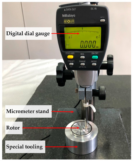
Figure 13.
Deformation measurement of the rotor web.

Table 3.
Plastic deformation of the stator and rotor webs after high impact test (10,000 g).
It is found that the stator plastic deformation of the motors (TRUM-2 and TRUM-4) with the disc spring are slightly larger than those (TRUM-1 and TRUM-3) without the disc spring, but the differences are extremely small with the order of magnitude of 10−6 m. However, the differences in the rotors are obvious. It can be seen that the rotors’ plastic deformation of TRUM-1 and TRUM-3 are 296 µm and 232 µm respectively which are much larger than those in TRUM-2 (13 µm) and TRUM-4 (10 µm). That is to say the rotors’ plastic deformation of the motors without the disc spring are larger than those of the motors with the disc spring. This trend is consistent in principle with the simulation results that the maximum stresses of rotors of the motors without the disc spring are much larger than those of the motors with the disc spring.
4.3. Mechanical Performance Test of the TRUMs
In order to study the influence of high overload on the performance of TRUM, the mechanical performance test of the four TRUMs before and after high impact are carried out. Figure 14 shows the experimental setups. The driving voltage is generated by a function generator (AFG 3022B; Tektronix Inc., Beaverton, AL, USA) and amplified to 400 Vp-p by two power amplifiers (HFVA-153; Foneng Technology Co., Ltd., Nanjing, China). The end of the test motor shaft is connected to a torque sensor (CYT-303; Tianyu Sensor Co., Ltd., Beijing, China), through which speed and output torque of the motor are measured. The results are finally displayed on the monitor of the data collector.
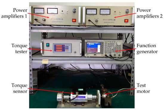
Figure 14.
Performance test setups for the TRUMs.
According to the mechanical performance data of each motor obtained from the experiment, the relationship between torque and speed is plotted, as shown in Figure 15.
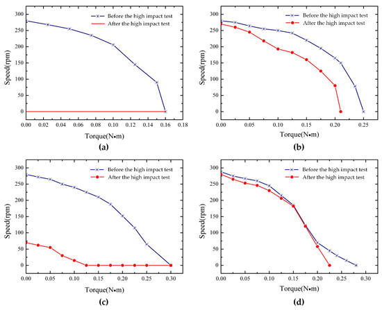
Figure 15.
The TRUMs’ performance before and after high-impact test: (a) TRUM-1; (b) TRUM-2; (c) TRUM-3; (d) TRUM-4.
Comparing the TRUMs in group 1, TRUM-1 performs well before the high-impact test with the maximum speed reaching 280 rpm and the stalling torque 0.16 N·m. However, after the high-impact test, the motor is damaged with no performance. For TRUM-2, the performance decreases after the impact test, the maximum speed decreases from 280 rpm to 270 rpm, and the stalling torque reduces from 0.25 N·m to 0.21 N·m. At the torque of 0.15 N·m, the speed decreases about 21.3%. This performance is acceptable. Comparing this with TRUMs in group 2, the maximum speed of TRUM-3 reaches 285 rpm and the stalling torque is 0.3 N·m. After the impact test, the motor performance drops severely. The maximum speed is 70 rpm and the speed drops rapidly to 0 until the torque is 0.15 N·m. Among the four motors, TRUM-4 has the lowest performance degradation after impact. The maximum speed decreases from 288 rpm to 280 rpm, and the stalling torque reduces from 0.3 N·m to 0.25 N·m. At the torque of 0.15 N·m, the speed decreases only 1.6%. The good performance of TRUM-4, indicating that the high acceleration of 10,000 g applied to this type of motor has little influence on its performance and the structure, means that it can be considered of high-overload resistance. Comprehensive analysis of the simulation and experimental results leads to the conclusion that the performance of the TRUMs with the disc spring is much less affected by the high overload than that without the disc spring, which indirectly proves that the disc spring applied to the structure of a TRUM acts as a good buffer and protects the motor from high overload.
5. Conclusions
In this research, the application of a TRUM in a high-overload environment (high acceleration of 10,000 g) is studied. Based on the structure of the PMR40 ultrasonic motor, the disc spring is used as the cushioning element to improve the weak rotor structure, and four new motors are designed. The FE software ADINA is used to establish the impact dynamics model of a TRUM working in a high-overload environment. A high-impact process of the four motors is simulated, and the stress of stator, rotor and friction plate of each motor and the force variation on the contact surfaces are studied. Finally, the simulation results are compared. Meanwhile, four actual TRUMs are manufactured. The high-impact test, measurement experiments for the stator and rotor webs plastic deformation, and a mechanical performance test before and after the impact test are carried out. Finally, the experimental results are compared and analyzed. It can be concluded that high overload will have different degrees of influence on the internal components of the TRUM. The occurrence of plastic deformation in the internal parts does not mean that the motor will not work immediately, but will cause a change in the motor’s performance. The performance degradation is directly proportional to the degree of damage to internal parts during the impact process. Combined with the impact dynamics simulation and experimental results, this leads to the conclusion that the TRUMs with the disc spring are more capable of high-overload resistance than the TRUMs without the disc spring. Performance of TRUM-4 with the modified rotor and disc spring decreased little after the 10,000 g acceleration high-impact test, so the structure of TRUM-4 is considered to be high-overload resistant and the purpose of structural improvement is achieved. In addition, the establishment of a TRUM impact dynamics model is of great significance for guiding the optimization of ultrasonic motors to expand their application in high-overload environments.
Author Contributions
Conceptualization, J.Z. and L.Y.; Methodology, J.Z.; Software, J.Z., C.M and H.C.; Validation, L.Y. and H.C.; Writing—original draft preparation, J.Z., L.Y. and C.M.; Writing—review and editing, X.S. and L.C.
Funding
This work was supported by the National Natural Science Foundation of China (grant No. 51575265), and the Project Funded by the Priority Academic Program Development of Jiangsu Higher Education Institutions (PAPD).
Acknowledgments
The authors are very grateful to Chunsheng Zhao, Rong-cheng Zhao, Xiangzhen Tao and Fuchun Gao from the NUAA Super Control Technology Co. Ltd. of financial support and providing TRUMs machining assistance.
Conflicts of Interest
The authors declare no conflict of interest.
References
- Cai, K.; Tian, Y.; Liu, X.; Fatikow, S.; Wang, F.; Cui, L.; Zhang, D.; Shirinzadeh, B. Modeling and controller design of a 6-DOF precision positioning system. Mech. Syst. Signal. Process. 2018, 104, 536–555. [Google Scholar] [CrossRef]
- Tian, X.; Liu, Y.; Chen, W.; Deng, J.; Liu, J. Development and experiment evaluation of an H-shape linear piezoelectric actuator operated in stepping mode. Ceram. Int. 2018, 44, S246–S249. [Google Scholar] [CrossRef]
- Li, J.; Zhou, X.; Zhao, H.; Shao, M.K.; Du, Y. Development of a Novel Parasitic-Type Piezoelectric Actuator. IEEE ASME Trans. Mechatronics 2017, 22, 541–550. [Google Scholar] [CrossRef]
- Zhang, J.; Tao, C.; Cheng, G.; Sui, Y.; Yang, H. Review of micro/nano machining by utilizing elliptical vibration cutting. Int. J. Mach. Tools. Manuf. 2016, 106, 109–126. [Google Scholar] [CrossRef]
- Sashida, T. Motor Device Utilizing Ultrasonic Oscillation. U.S. Patent Application No. 4,562,374, 31 December 1985. [Google Scholar]
- Zhao, C.S. Ultrasonic Motors: Technologies and Applications; Springer: Berlin/Heidelberg, Germany, 2011. [Google Scholar]
- Ren, J.H.; Chen, C.; Zhou, J.L. Research on the overload characteristic of Traveling Wave Type Rotary Ultrasonic Motor. In Proceedings of the 2013 Symposium on Piezoelectricity, Acoustic Waves, and Device Applications, Changsha, China, 25–27 October 2013. [Google Scholar]
- Chen, C.; Ren, J.H.; Shi, M.Y. Impact Dynamics Simulation and Experiment of Rotating Traveling Wave Ultrasonic Motor. J. Vib. Meas. Diagn. 2014, 34, 8–14. (In Chinese) [Google Scholar]
- Sun, D.; Wang, X.J.; Chen, C.; Wang, J.; Liu, Y.F. Dynamic response mechanism of rotary type ultrasonic motor under high impact load. In Proceedings of the ASME 2016 international mechanical engineering congress and exposition, Phoenix, AZ, USA, 11–17 November 2016. [Google Scholar]
- Sun, D.; Tang, Y.J.; Wang, J.; Wang, X.J. Concept and experimental validation of piezoelectric motor–based acceleration sensor in shock environment. J. Intel. Mater. Syst. Struct. 2019, 30, 2112–2124. [Google Scholar] [CrossRef]
- Xu, X.; Xiu, T.; Fu, H.; Wang, Y.; Hao, Y. In Study on High Overload Characteristics of Ultrasonic Electric Actuator. In Proceedings of the International Conference on Intelligent & Interactive Systems & Applications, Beijing, China, 1 November 2017. [Google Scholar]
- Fawazi, N.; Yoon, J.; Oh, J.; Lee, J. Geometric Design of a Slotted Disc Spring for a Prescribed Load-Displacement Function. In Proceedings of the ASME 2010 International Mechanical Engineering Congress & Exposition, Vancouver, BC, Canada, 12–18 November 2010. [Google Scholar]
- Schremmer, G. The Slotted Conical Disk Spring. J. Eng. Ind. 1973, 95, 765–770. [Google Scholar] [CrossRef]
- Fawazi, N.; Yang, I.H.; Kim, J.S.; Lee, J.Y.; Kim, H.S.; Oh, J.E. An Inverse Algorithm of Nonlinear Load-Displacement for a Slotted Disc Spring Geometric Design. Int. J. Precis. Eng. Manuf. 2013, 14, 137–145. [Google Scholar] [CrossRef]
- Alabuzhev, P.M.; Gritchin, A.A.; Kim, L.I.; Migirenko, G. Vibration-Protection System with Quasi-Zero Stiffness; CRC Press: Boca Raton, FL, USA, 2002. [Google Scholar]
- Valeev, A.R.; Zotov, A.N.; Kharisov, S.A. Erratum to: Application of Disk Springs for Manufacturing Vibration Isolators with Quasi-Zero Stiffness. Chem. Pet. Eng. 2016, 51, 194–200. [Google Scholar] [CrossRef]
- Wen, B.C. Machinery Design Handbook; China Machine Press: Beijing, China, 2007. [Google Scholar]
- Niu, F.; Meng, L.S.; Wu, W.J.; Sun, J.G.; Zhang, W.M.; Meng, G.; Rao, Z.S. Design and analysis of a quasi-zero stiffness isolator using a slotted conical disk spring as negative stiffness structure. J. Vibroeng. 2014, 16, 1769–1785. [Google Scholar]
- Meng, L.; Sun, J.; Wu, W. Theoretical Design and Characteristics Analysis of a Quasi-Zero Stiffness Isolator Using a Disk Spring as Negative Stiffness Element. Shock. Vib. 2015, 2015, 19. [Google Scholar] [CrossRef]
- Bathe, K.J. ADINA Handbook; ADINA R & D, Inc.: Watertown, NY, USA, 2017. [Google Scholar]
- Bathe, K.J. ADINA User Interface Command Reference Manual; ADINA R & D, Inc.: Watertown, NY, USA, 2017. [Google Scholar]
- Ren, W.H.; Yang, L.; Ma, C.C.; Li, X.N.; Zhang, J.J. Output performance simulation and contact analysis of traveling wave rotary ultrasonic motor based on ADINA. Comput. Struct. 2019, 216, 15–25. [Google Scholar] [CrossRef]
- Bathe, K.J. Finite Element Procedures; Prentice Hall: Upper Saddle River, NJ, USA, 2006. [Google Scholar]
© 2019 by the authors. Licensee MDPI, Basel, Switzerland. This article is an open access article distributed under the terms and conditions of the Creative Commons Attribution (CC BY) license (http://creativecommons.org/licenses/by/4.0/).