Article

Deformations of FRP–Concrete Composite Beam: Experiment and Numerical Analysis

1
Laboratory of Innovative Building Structures, Vilnius Gediminas Technical University (VGTU), Saulėtekio av. 11, Vilnius LT-10223, Lithuania
2
Department of Steel and Composite Structures, VGTU, Saulėtekio av. 11, Vilnius LT-10223, Lithuania
*
Author to whom correspondence should be addressed.
Appl. Sci. 2019, 9(23), 5164; https://doi.org/10.3390/app9235164
Submission received: 2 November 2019 / Revised: 22 November 2019 / Accepted: 25 November 2019 / Published: 28 November 2019
(This article belongs to the Section Civil Engineering)

Abstract

:

Featured Application

The proposed numerical analysis principles are applicable for a design for serviceability of fibre-reinforced polymer (FRP)–concrete elements.

Abstract

Advanced materials have been created for structural application during the past decades. Engineers, however, faced severe problems due to the absence of a reliable technique for ensuring the required structural properties minimising the amount of material used. A lack of constitutive models for the analysis of the structural systems also exists. Residual stiffness of flexural concrete elements subjected to short-term load is the focus of this research. Tension-stiffening models were developed to represent the deformation response of the members reinforced with internal bars. This study examines the suitability of the tension-stiffening modelling approach for simulating the deformation behaviour of the composite specimens comprising glass fibre-reinforced polymer (GFRP) pultruded profile adhesively bonded to the tensile surface of the concrete beam. The study employs a nonlinear finite element approach and analytical model to simulate the deformation behaviour of the flexural elements.

Graphical Abstract

1. Introduction

Advanced materials were created for structural application. The use of concrete and fibre-reinforced polymers (FRP) composites has emerged as one of the most exciting and promising techniques in structural engineering. A synergy of the high performance of FRP materials in tension and concrete in compression enables the development of efficient structural systems [1,2]. However, engineers faced severe problems due to the absence of a reliable technique for ensuring the required structural properties minimising the amount of material used [3].
The first attempts of application of FRP materials are related to the flexural strengthening of reinforced concrete (RC) bridges [4]. At that moment, adhesively bonded external steel reinforcement was the commonly acceptable option of achieving structural rehabilitation. This method was originally invented in France in the mid-sixties; in the early seventies, it was further developed in Switzerland, Germany and England and is nowadays state-of-art in Western Europe [5]. However, the drawbacks of the steel application overrule the efficiency of the bonding technique. The heaviness of steel plates causes inconvenience of the handling on construction site. The need for the extension of element lengths results in the welded connections, which corrupt the adhesive bond. The long-term creep tests reveal progressively growing spots of corrosion at the joint between the steel and adhesive [5]. The mentioned problematic points have made it necessary to look for more appropriate materials and strengthening technologies. Nowadays, there is a wide range of potential applications of FRP reinforcement that cover both initial design as well as strengthening and rehabilitation [6,7,8]. However, the brittleness of the FRP systems should be pointed out as the main drawback: FRP materials experience linear elastic behaviour up to failure that causes unfavourable brittleness of the composite [9,10,11].
Commonly, FRP strips are adhesively bonded to the most tensioned surface of a deficient structural member [12], and the mechanical parameters of the bond often determine the failure of the strengthening system [12,13,14,15]. Therefore, a comprehensive understanding of the bond behaviour plays an essential role in determining the performance of FRP–concrete elements.
Glass fibre-reinforced polymers (GFRP) have great potential as construction material and enable structural engineers to consider them as a feasible alternative to steel for various structural applications [6,9,16,17]. Tests of GFRP–concrete composite elements were initially carried out to estimate the efficiency of the rehabilitation systems [10,18,19]. Compared with the use of steel plates, this solution presents several advantages, such as the ease of application, the lower self-weight, and resistance to corrosive environments. The GFRP materials are less expensive than carbon fibre-reinforced polymers (CFRP). Therefore, GFRP is often used for engineering practice. However, due to the low value of the modulus of elasticity, the GFRP–concrete elements exhibit large deformations. Thus, the serviceability criterion governs the design of such structures. Numerical simulations offer a powerful tool for the solution of the serviceability problems [20], but adequate constitutive models are necessary for that purpose.
Residual stiffness of flexural concrete elements subjected to short-term load is the focus of this research. This parameter is characteristic of the structural integrity of cracked concrete. In numerical simulations, tension-stiffening models can represent the stiffness decay in an average manner. Numerous studies investigated the tension-stiffening issue. However, only several works addressed flexural effects. Fundamental studies by Kaklauskas & Ghaboussi [21] and Torres et al. [22] should be mentioned in this context. Gribniak et al. [23,24] proposed an experimental procedure to estimate the flexural response of concrete elements with different types of composite reinforcement. In this study, the proposed test procedure is used to verify the performance of the simplified tension-stiffening approach to represent the deformation behaviour of a GFRP–concrete composite element. A nonlinear finite element model and an engineering approach are developed for that purpose.

2. Test Program

As shown in Figure 1, two series of concrete specimens with the same geometry of concrete cross-section and different reinforcement types are considered—two nominally identical beams composed each set of samples. The composite specimens, comprising GFRP pultruded profile and concrete beam (B1-GFRP and B2-GFRP), and the elements reinforced with ordinary steel bars (B1 and B2) were tested. The geometry of the GFRP–concrete beam was chosen to simplify numerical simulations. These specimens should be considered only as a prototype of the composite structural systems mentioned in the introduction. The total area of the bar reinforcement was selected to ensure a similar flexural rigidity (~6 × 10¹¹ N·mm2) of both series of the specimens. The RC specimens are used to determine the tension-stiffening model of the concrete that further is applied for the modelling of the GFRP–concrete beams.

2.1. Material Properties

The beam specimens were poured in two batches using the same mix proportions. Together with the beams, 100 mm cubes were produced to determine the strength of the concrete. The composition of the concrete (for a cubic meter) is the following: 356 kg of cement CEM I 42.5 R, 163 l of water, 177 kg of limestone powder, 890 kg of 0/4 mm sand, and 801 kg of 4/16 mm crushed aggregates; 1.97% (by the cement weight) of the superplasticiser Mapei Dynamon XTend and 3.5 kg of the admixture SCP 1000 Optimizer. The concrete also included 4.2 kg of the Durus EasyFinish synthetic macro-fibres and 0.6 kg of the Crackstop M Ultra synthetic micro-fibres. The fibres were used to avoid a brittle failure of the concrete [12]. The strength of the concrete was estimated using the compression test results of the 100 mm cubes. It was equal to 57.7 MPa at the beams testing day.
Figure 1 shows the cross-sections of the beam samples. The slab-like shape of the specimens was developed in [23] to form multiple cracks in the pure bending zone of relatively small samples. A 100 × 200 × 1000 concrete prism and 10 × 80 × 1000 pultruded GFRP profile comprise the composite section (Figure 1a). The modulus of elasticity (= 58.1 GPa) and strength (= 350 MPa) of the polymer profile were determined experimentally applying the uniaxial tensile load along the direction of the glass filaments.
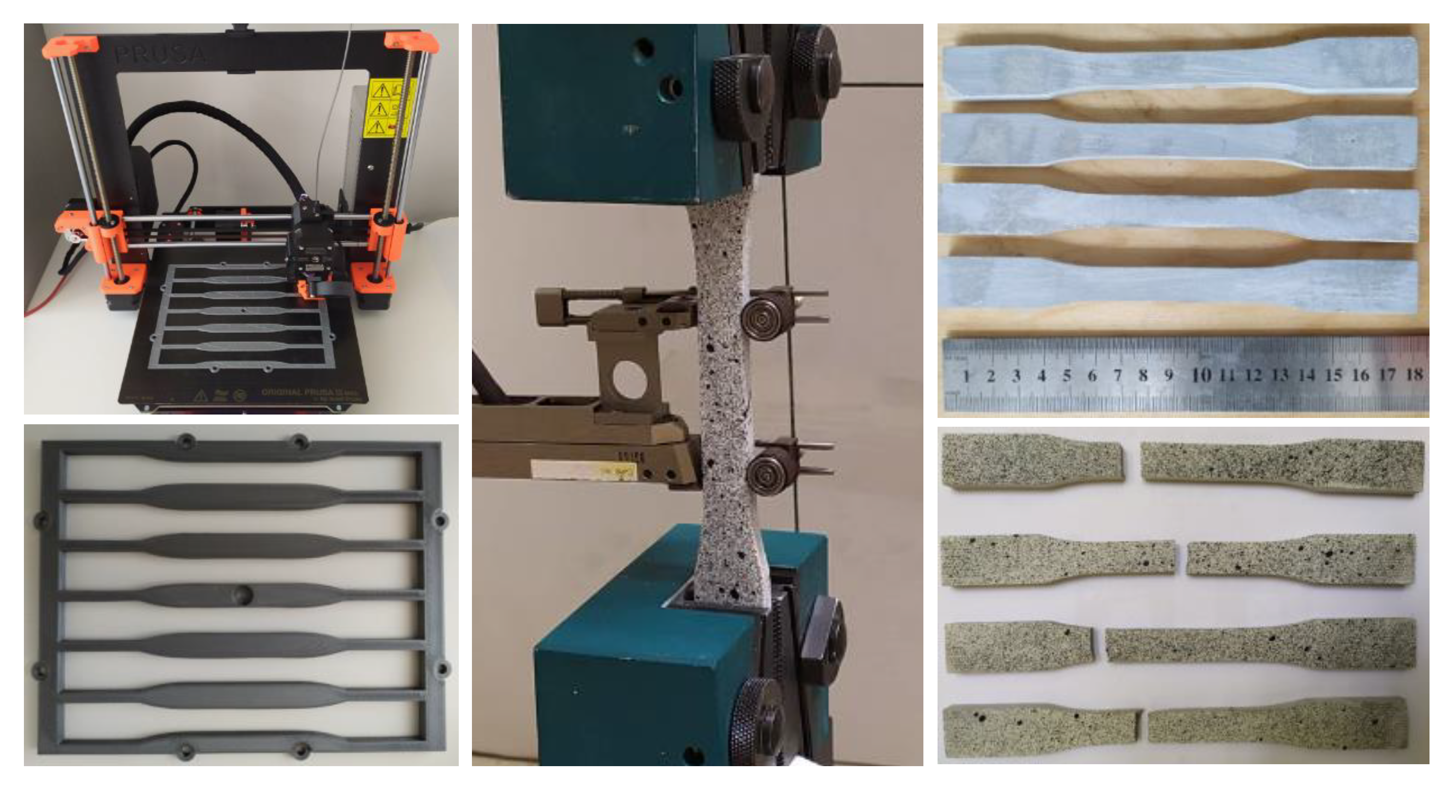
The GFRP profile was adhesively bonded to the tensile surface of the beam using the two-component epoxy resin MapeWrap 11. The mechanical parameters of the adhesive were determined according to ASTM D 3039 standard. The moulds of the bone-shaped specimens were produced of polylactic acid (PLA) using a 3D printing technique. Figure 2 shows the mould production, test apparatus and geometry of the tensile specimen. The modulus of elasticity and tensile strength of the adhesive was found equal to 7.47 GPa and 15 MPa.
Beams B1 and B2 were reinforced with three 8 mm steel bars (Figure 1b). Hot-rolled deformed bars were used. Three bar samples were tested using a universal testing machine to obtain the modulus of elasticity and yield strength, which was found equal to 196 GPa and 560 MPa.

2.2. Bending Test Specimens

This study employs the experimental procedure [23,24] developed to estimate the residual flexural stiffness of concrete elements with composite reinforcement. The proposed testing layout enables the formation of multiple cracks (more than 10) in a pure bending zone of relatively small specimens. This is the useful feature for ensuring the reliability of estimation of the residual stiffness, as the variation of the crack number has no significant effect on the analysis results. The 1000-mm-long specimens are tested under the four-point-loading scheme with 600 mm pure bending zone. The monitoring parameters include vertical displacement and surface deformations in the bending region. The moment–curvature response averaged over the pure bending zone is the analysis object.
Table 1 shows the main parameters of the bending test specimens. In this table, h, b and d are the height, width and effective depth of the cross-section, respectively; Ar and Er are the area and the modulus of elasticity of reinforcement, respectively; and t and Ea are the thickness and the modulus of elasticity of the adhesive, respectively.

2.3. Test Apparatus

The beam specimens were tested using a 5000 kN capacity servo-hydraulic machine at displacement control. The loading speed was equal to 0.4 mm/min. A load cell was used to measure the applied load. Figure 3 shows the loading scheme and test apparatus. Linear variable displacement transducers (LVDTs; L10L15, Figure 3), attached in two continuous lines to the side surface “(1)” of the specimen, were used to monitor flexural deformations of the concrete prism. Nine LVDTs (L1L9, Figure 3) measured the vertical displacements in pure bending zone. Such arrangement of the devices enables cross-validation of the test outcomes: the measurement outcomes enable to construct three each other independent moment–curvature diagrams suitable for the tension-stiffening analysis.
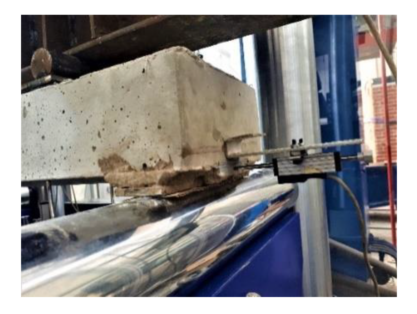
The construction of the support joints of GFRP–concrete beams has prevented slip of the pultruded profile that was fixed over the supports using the rapid assembly mortar Ceresit CX 5. The displacement was monitored using an LVDT devise attached to the boundary surface of the specimen, as shown in Figure 4.
The data logger Almemo 5690-2 was used to collect the output data of all LVDT and the load cell. Deformations of the side surface “(2)” (Figure 3) were monitored using a digital image correlation (DIC) system that also enables tracking the development of cracks. Two cameras Imager Elite 5M were used for that purpose. The cameras were placed on a tripod at the 3 m distance from the specimen; the distance between the cameras was equal to 0.4 m. The cameras, incorporating a charge-coupled device (CCD) detector, have a resolution of 2456 × 2085 pixel at the 12.2 fps rate.

2.4. Test Results

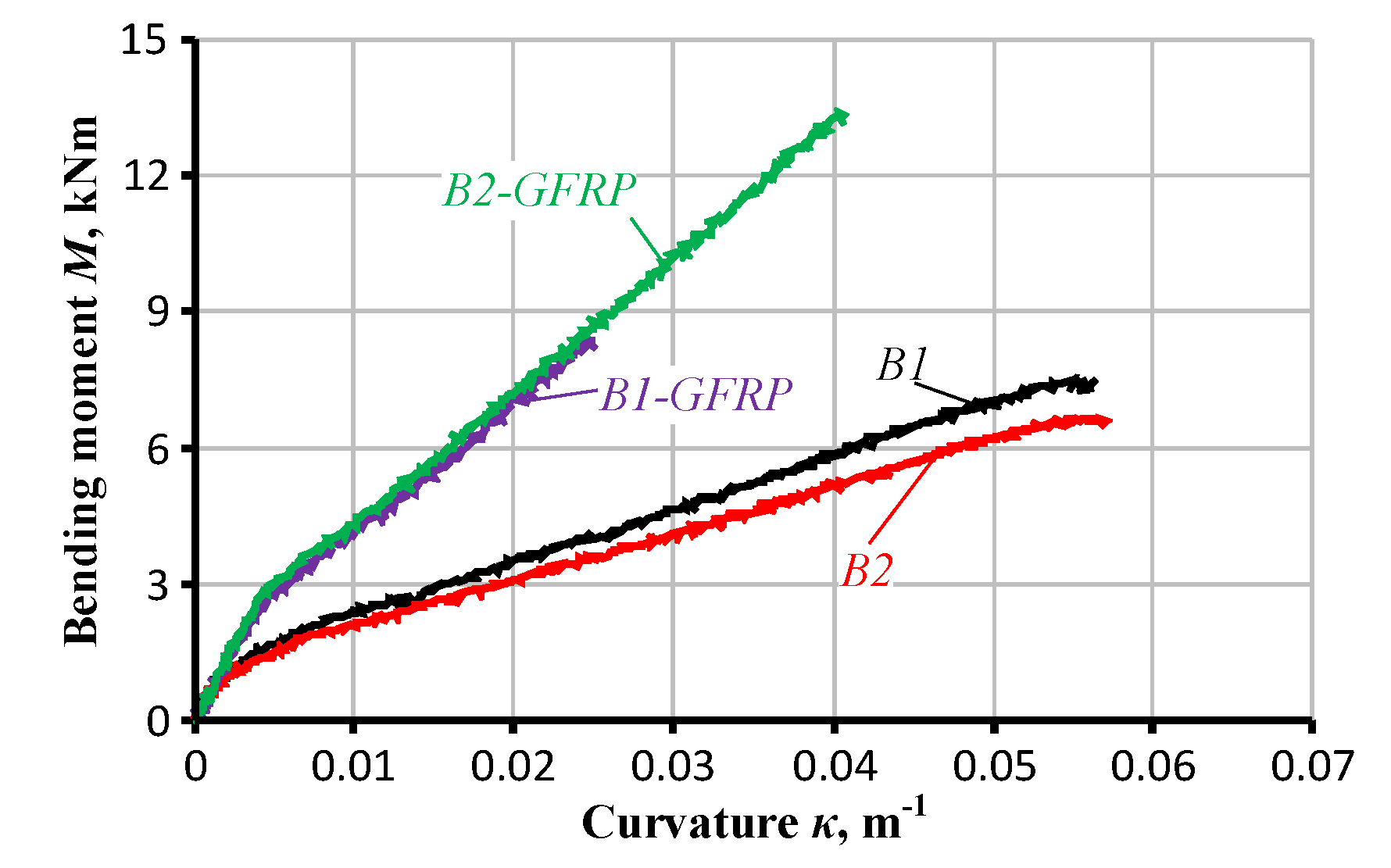
The curvatures averaged over the pure bending zone of the test specimens determine the tension-stiffening stresses. The application of multiple devices enables to estimate the average response in three alternative ways. Figure 5 shows the moment–curvature diagrams of the beams B2-GFRP and B2 derived using the monitoring results of the deflections and surface deformations. The surface deformations were estimated using the outcomes of the LVDT and DIC systems. Figure 5 demonstrates a perfect agreement between the curvature estimation results. Further analysis employs the moment–curvature relationships (Figure 6) derived using the deflection monitoring results.

3. Deformation Analysis

The performance of the simplified tension-stiffening approach to represent the deformation behaviour of the GFRP–concrete element is the object of the analysis. The RC specimens are used to determine tension-stiffening model of the concrete. The inverse procedure developed by Kaklauskas & Ghaboussi [21] and further modified by Gribniak et al. [25] is used for the analysis.

3.1. Tension-Stiffening Model

The tension-stiffening model, attributed to the tensile concrete, is derived following the inverse procedure described in the referred article [25]. The analysis employs the assumption of the uniform tension-stiffening relationship over the area of the tensile concrete. The perfectly elastic material models of the compressive concrete and steel reinforcement are assumed.
Kaklauskas & Ghaboussi [21] formulated the calculation principles: for a given moment–curvature diagram, a stress–strain tension-stiffening relation is computed from the equilibrium conditions of axial forces and bending moments. For a given load increment, two equilibrium equations are iteratively solved, bringing a solution for the neutral axis coordinate and the stress in the extreme tension fibre of the considered cross-section. As the bottom layer has the maximum deformation, other tension fibres of concrete have smaller strains falling within the portion of the already determined stress–strain diagram.
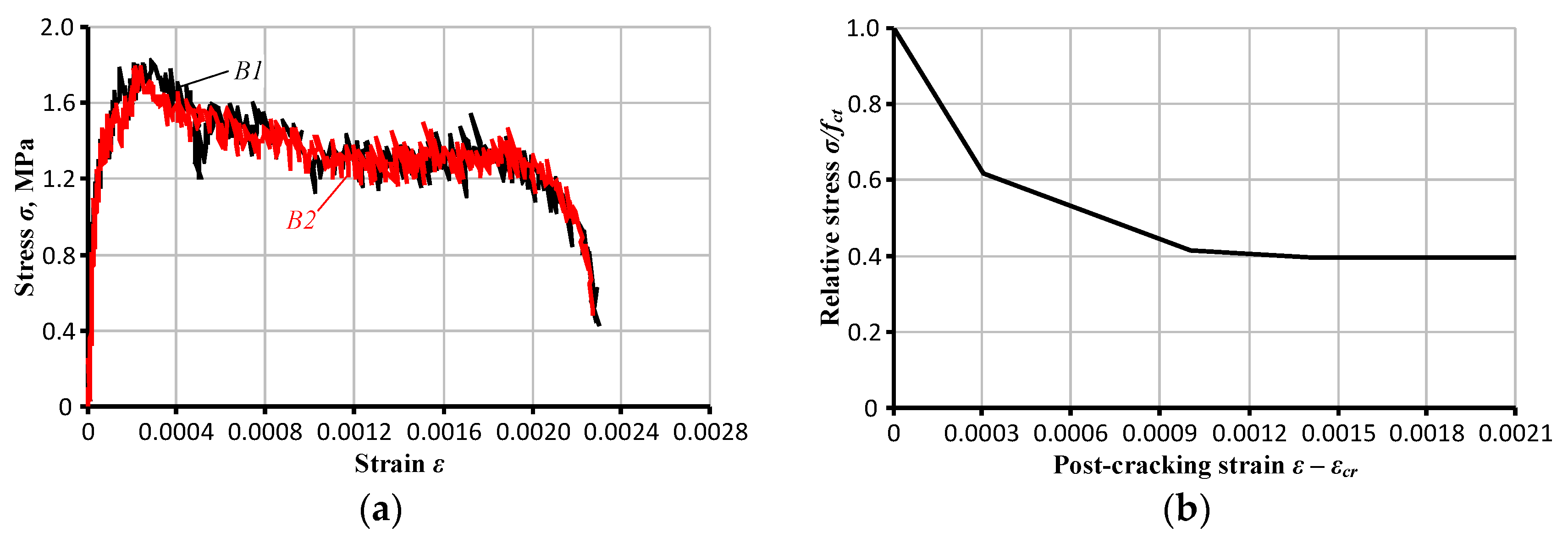
Figure 7 shows the tension-stiffening relations of the beams B1 and B2 and the corresponding material model that is assumed for the tensile concrete in numerical analysis. The sudden decay of the tension-stiffening diagram corresponding to the strain exceeding 2‰ (Figure 7a) is a consequence of the yielding of the steel reinforcement. The tension-stiffening model (Figure 7b) does not account for this decrease since it is developed to represent the behaviour of the GFRP–concrete composite.

3.2. Numerical Simulations

Deformation behaviour of the GFRP–concrete specimen is considered in a plane stress state with nonlinear constitutive law for concrete. The analysis is carried out using the finite element (FE) software Atena. Half of the beam is modelled following the symmetry conditions. The concrete prism and GFRP profile are simulated as separate macroelements. The GFRP is assumed as an elastic material. All simulations assume perfect bond between the macroelements (i.e., no slip was enabled). The validity of this assumption was verified experimentally—the LVDT device shown in Figure 4 indicated no relative displacement of the GFRP profile. Different sizes of FE meshes are used to represent the concrete (= 5 mm), the GFRP profile (= 2 mm) and the epoxy adhesive layer (= 0.7 mm). Figure 8 shows the FE model and boundary conditions of the analysis.
Three alternative numerical models are considered. The perfect bond and tension-stiffening model (Figure 7b) describe the deformation behaviour of the GFRP–concrete specimen in the first simulation. An elastic behaviour of the compressive concrete is assumed as well. An additional macroelement is used in the other two simulations to represent the adhesive that is modelled as a perfectly elastic material. Table 1 describes the properties of the materials.
Material model of the concrete determines the difference between the numerical simulations. Table 2 defines the parameters of the FE models. The 3D Nonlinear Cementitious 2 User material model, based on the concept of smeared cracks and damage [20], is assumed in the first simulation. Cracking of the concrete is modelled using the tension-stiffening diagram shown in Figure 7b. The fixed crack approach is used for that purpose. The necessary input parameters of the concrete, i.e., the tensile strength (fct), the modulus of elasticity (Ec) and the Poisson’s ratio (ν) are assessed with fib Model Code 2010 [26] using respective values of the compressive strength. The adhesive is not modelled, assuming the perfect bond between the concrete and GFRP profile.
The Sbeta material model is used in the second and third FE simulations. In contrast to the nonlinear constitutive law (Figure 7b) used in Model #1, a fracture mechanics approach, based on the crack band model [27], is used to define the softening mechanism of the tensile concrete. It is based on the softening law proposed by Hordijk [28]; the fracture energy (Gf) describes this mechanism. In a similar manner as in Model #1, fib Model Code 2010 [26] defines the strength, fct; the modulus, Ec; the ratio, ν; and the energy, Gf. The second model assumes a perfectly elastic behaviour of the compressive concrete, whereas the default nonlinear model of the compressive concrete is used in the third simulation. The authors of [20] provide a detail description of the material models.

4. Discussion

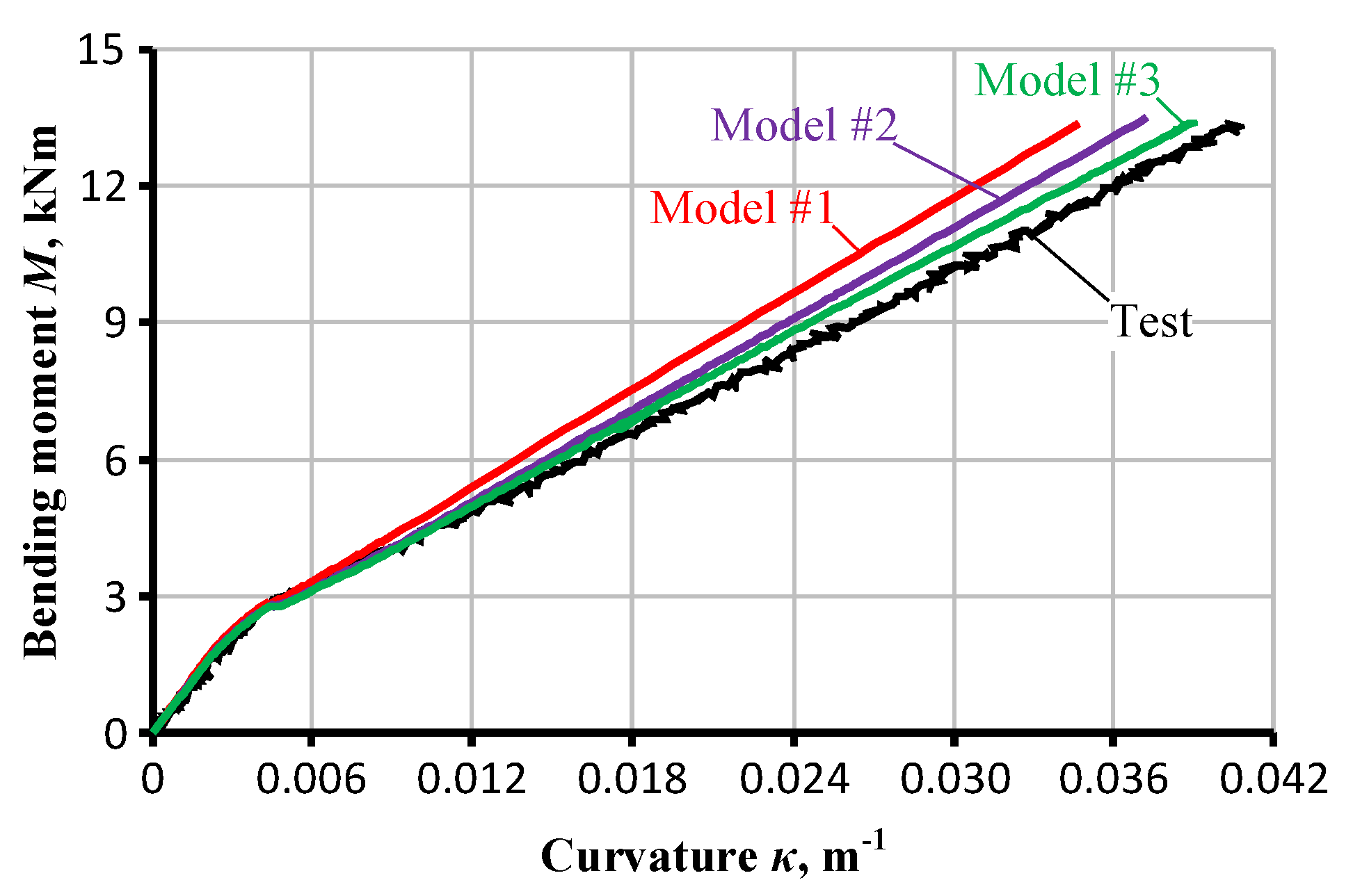
Figure 9 shows the moment–curvature diagrams obtained using the results of the FE simulations; Model #3 demonstrates the best agreement to the experimental results. This outcome supports the modelling results reported in the referred article [29], which demonstrates the capabilities of a detail FE model to assess strain distribution within the concrete of tension prisms reinforced with multiple bars. The application of over-simplified approaches to the design of complex structures in real-life can induce substantial errors. However, limitations of the current hardware do not enable to develop the detail FE models suitable for engineering practice.
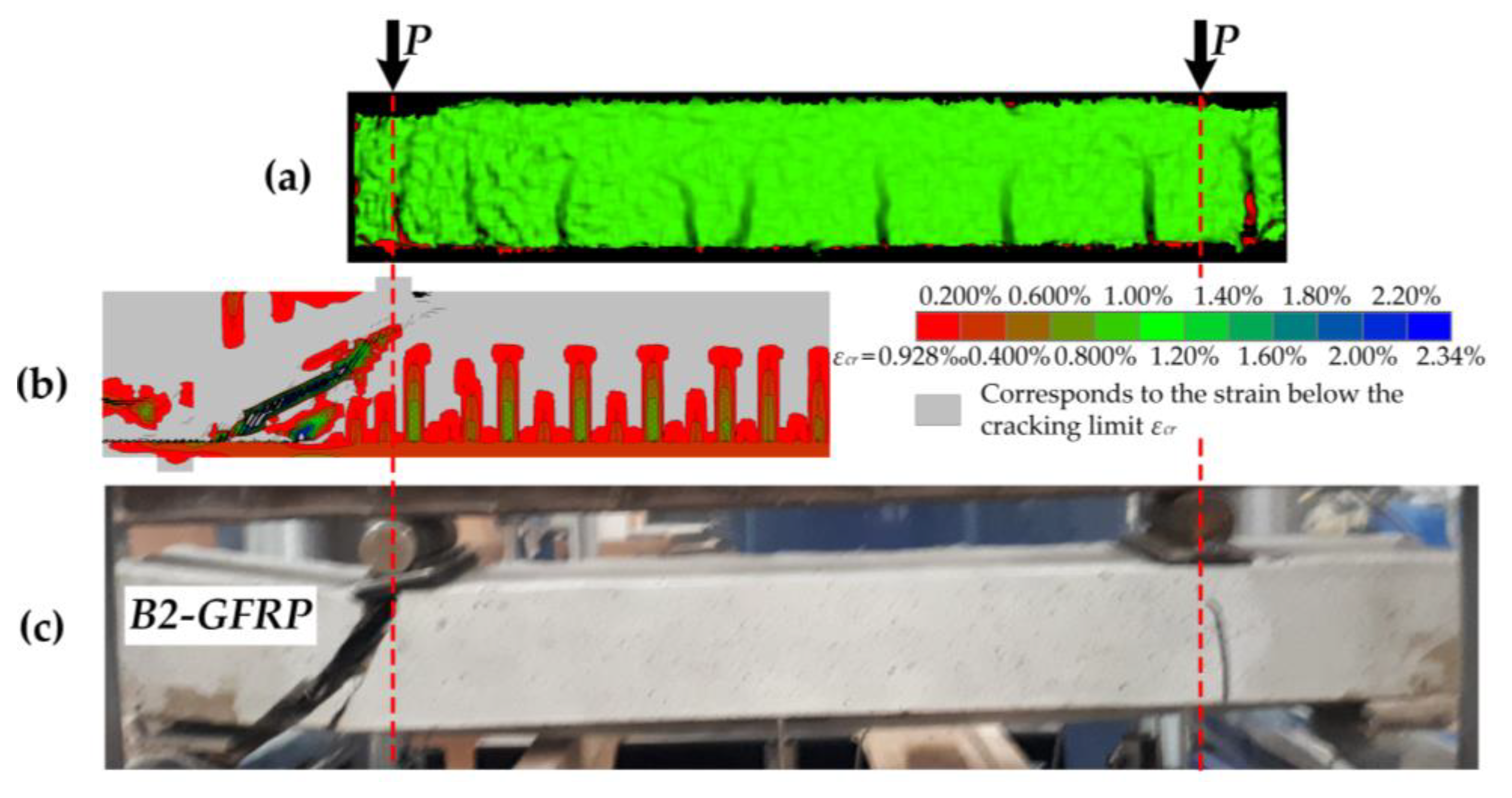
Model #3 was also used to analyse the cracking and failure behaviour of the GFRP–concrete beam. The cracking results identified by the DIC system are used as the reference. Figure 10 demonstrates the crack pattern and strain distribution in the concrete of the beam specimen B2-GFRP. The presented results correspond to the average curvature κ = 0.03 m−1; the grey-filled areas indicate the strains below the theoretical cracking limit εcr = 0.093‰. A good agreement between the numerical outcome (Figure 10b) and test result (Figure 10a) can be observed.
The development of a critical shear crack caused the failure of the GFRP–concrete specimen (Figure 10c). This outcome supports the finding reported in the referred study [24] that demonstrated low resistance of FRP composite reinforcement systems to the transverse loads. Model #3 was capable of representing the failure process adequately (Figure 10b).
The tension-stiffening approach (Model #1) was not capable of predicting the deformation response of FRP–concrete elements. This approach is only the attribute of FE models with reinforcement simulated as embedded truss elements [20]. Contrarily, the tension-softening effect is predominant for the modelling of FRP–concrete specimens: the application of Model #2 improved the curvature predictions (Figure 9). Further improvement was the result of the implementation of a nonlinear constitutive model of compressive concrete.
The utilisation of detail approaches (e.g., Models #2 and #3), however, requires refined FE meshes. This situation becomes critical in a 3D formulation [29] when the number of FE increases drastically. The Atena software was capable only to simulate a small segment of the specimen that is unacceptable for engineering application.
A simplified engineering approach is proposed to solve this problem. It employs the following simplifications: the compressive concrete is assumed as a perfectly elastic material; the contribution of the adhesive is neglected. Two loading stages are distinguished. If the applied load does not exceed the cracking moment (Mcr), the concrete is considered as a perfectly elastic material. After the cracking, the contribution of the tensile concrete is neglected. The curvature is calculated as
κ   =   { M E c ( b h 3 12 + b h [ y c , e l h 2 ] 2 ) + E r ( b r h r 3 12 + A r [ d y c , e l ] 2 ) , M M c r ; M 1 12 E c y c , c r 2 b ( 3 h + y c , c r ) + E r A r ( d y c , c r ) ( d h + y c , c r 2 ) , M > M c r .
Figure 1 and Table 1 explain notations in Equation (1); the following equations describe the position of the neutral axis in the elastic and cracking stage, respectively,
y c , e l   =   b h 2 2 E c + d E r A r b h E c + E r A r ,
y c , c r   =   4 ( E r A r ) 2 + 8 b d E c E r A r 2 E r A r 2 b E c .
The cracking moment is calculated as
M c r   =   f c t b h 3 12 ( h y c , e l ) ,
where fct is the tensile strength of the concrete.
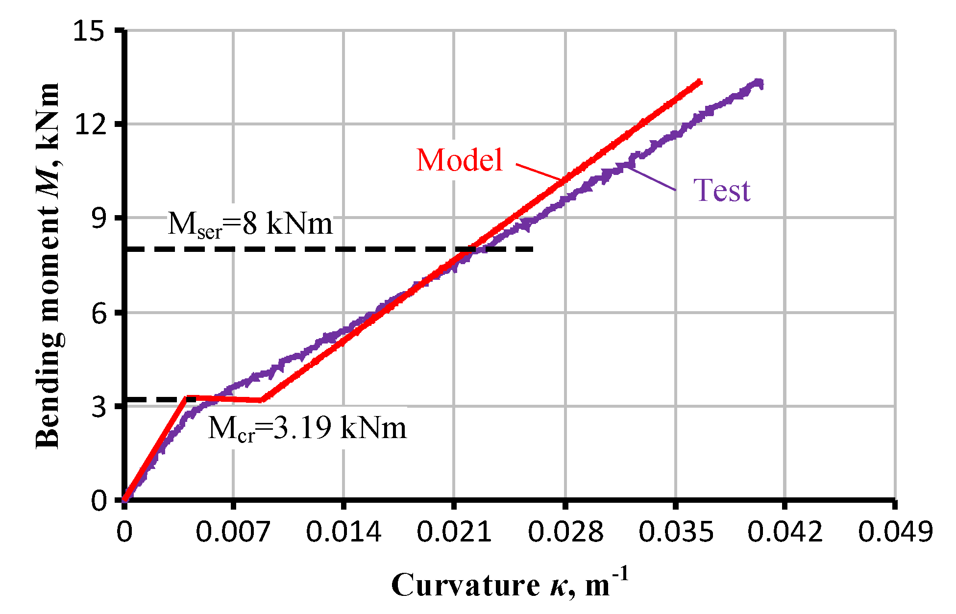
Figure 11 demonstrates that the predictions are in a satisfactory agreement with the test results. The prediction error, corresponding to the service load, is approximately equal to 2%. The service load is determined as 60% of the theoretical ultimate load-bearing capacity of the beam.
It is important to note that the suitability of the proposed simplified model is limited to the analysis of the GFRP–concrete beams. The work in [20,21,22,23,24,25] demonstrated that the deformation prediction of the beam specimens reinforced with internal bars requires a description of the tension-stiffening effect. Figure 7a supports the above inference showing a substantial portion of the stresses accumulated in the tension concrete during the cracking process.

5. Conclusions

Verification of the performance of the simplified tension-stiffening approach to represent the deformation behaviour of a glass fibre-reinforced polymer (GFRP)-concrete element is the focus of this research. Two series of specimens with the same geometry of concrete cross-section and different reinforcement types were considered—two nominally identical beams composed each set of samples. The geometry of the GFRP–concrete beam was chosen to simplify numerical simulations. This specimen is only a prototype of structural systems. The beam specimens reinforced with steel bars were used to determine the tension-stiffening model of the concrete that further was applied for the modelling of the GFRP–concrete beams. A nonlinear finite element (FE) model was developed for that purpose. The following conclusions were made.
  • The tension-stiffening approach was not capable of predicting the deformation response of GFRP–concrete elements. The adequate application of this approach is limited to the FE models with reinforcement simulated as embedded truss elements. Contrarily, the tension-softening effect is predominant for the modelling of FRP–concrete specimens.
  • A detail FE model is capable of representing deformation behaviour and failure mechanisms of GFRP–concrete composite elements. However, engineering applications of such an approach can be problematic because of the existing hardware limitations.
  • A simplified model is proposed to solve the above problem. The model assumes a perfectly elastic model of the compressive concrete; the contribution of the tensile concrete and adhesive are neglected. The predictions are in a satisfactory agreement with the experimental results. The prediction error, corresponding to the service load, is approximately equal to 2%.

Author Contributions

Conceptualization V.G. and A.Š.; methodology V.G.; software A.S.; validation I.M., A.R.; investigation, I.M. and A.S.; resources V.G.; data curation A.R. and A.S.; writing—original draft preparation A.S., A.R.; writing—review and editing V.G.; visualization A.S.; supervision V.G.; project administration I.M.

Funding

The European Social Fund funded this research and APC within the framework of the project “Development of Competences of Scientists, other Researchers and Students through Practical Research Activities” (Project No 09.3.3-LMT-K-712).

Acknowledgments

The funding provided by the European Social Fund is sincerely acknowledged.

Conflicts of Interest

The authors declare no conflicts of interest.

References

  1. Zuo, Y.; Mosallam, A.; Xin, H.; Liu, Y.; He, J. Flexural performance of a hybrid GFRP-concrete bridge deck with composite T-shaped perforated rib connectors. Compos. Struct. 2018, 194, 263–278. [Google Scholar] [CrossRef]
  2. Siwowski, T.; Rajchel, M.; Kulpa, M. Design and field evaluation of a hybrid FRP composite—Lightweight concrete road bridge. Compos. Struct. 2019, 230, 111504. [Google Scholar] [CrossRef]
  3. Sapuan, S.M.; Mansor, M.R. Concurrent engineering approach in the development of composite products: A review. Mater. Des. 2014, 58, 161–167. [Google Scholar] [CrossRef]
  4. Meier, U. Structural tensile elements made of advanced composite materials. Struct. Eng. Int. 1999, 9, 281–285. [Google Scholar] [CrossRef]
  5. Czaderski, S.; Meier, U. EBR strengthening technique for concrete, long-term behaviour and historical survey. Polymers 2018, 10, 77. [Google Scholar] [CrossRef] [PubMed]
  6. Correia, J.R. Pultrusion of advanced fibre-reinforced polymer (FRP) composites. In Advanced Fibre-Reinforced Polymer (FRP) Composites for Structural Applications; Woodhead Publishing Limited: Cambridge, UK, 2013; pp. 207–251. [Google Scholar]
  7. Custódio, J.; Cabral-Fonseca, S. Advanced fibre-reinforced polymer (FRP) composites for the rehabilitation of timber and concrete structures: Assessing strength and durability. In Advanced Fibre-Reinforced Polymer (FRP) Composites for Structural Applications; Woodhead Publishing Limited: Cambridge, UK, 2013; pp. 814–882. [Google Scholar]
  8. Wan, B. Using fiber-reinforced polymer (FRP) composites in bridge construction and monitoring their performance: An overview. In Advanced Composites in Bridge Construction and Repair; Woodhead Publishing Limited: Cambridge, UK, 2014; pp. 3–29. [Google Scholar]
  9. Akbarzadeh, H.; Maghsoudi, A.A. Experimental and analytical investigation of reinforced high strength concrete continuous beams strengthened with fiber reinforced polymer. Mater. Des. 2010, 31, 1130–1147. [Google Scholar] [CrossRef]
  10. Saadatmanesh, H.; Ehsani, M.R. RC beams strengthened with GFRP plates. I: Experimental study. J. Struct. Eng. ASCE 1991, 117, 3417–3433. [Google Scholar] [CrossRef]
  11. Taheri, F.; Shahni, K.; Widiarsa, I. On the parameters influencing the performance of reinforced concrete beams strengthened with FRP plates. Compos. Struct. 2002, 58, 217–226. [Google Scholar] [CrossRef]
  12. Gribniak, V.; Ng, P.L.; Tamulenas, V.; Misiūnaitė, I.; Norkus, A.; Šapalas, A. Strengthening of fibre reinforced concrete elements: Synergy of the fibres and external sheet. Sustainability 2019, 11, 4456. [Google Scholar] [CrossRef]
  13. Wu, Z.J.; Davies, J.M. Mechanical analysis of a cracked beam reinforced with an external FRP plate. Compos. Struct. 2003, 62, 139–143. [Google Scholar] [CrossRef]
  14. Achintha, M.; Burgoyne, C.J. Fracture mechanics of plate debonding: Validation against experiment. Constr. Build. Mater. 2011, 25, 2961–2971. [Google Scholar] [CrossRef]
  15. Wroblewski, L.; Hristozov, D.; Sadeghian, P. Durability of bond between concrete beams and FRP composites made of flax and glass fibers. Constr. Build. Mater. 2016, 15, 800–811. [Google Scholar] [CrossRef]
  16. Hollaway, L.C. A review of the present and future utilisation of FRP composites in the civil infrastructure with reference to their important in-service properties. Constr. Build. Mater. 2010, 24, 2419–2445. [Google Scholar] [CrossRef]
  17. Li, Z.; Khennane, A.; Hazell, P.J.; Remennikov, A.M. Performance of a hybrid GFRP-concrete beam subject to low-velocity impacts. Compos. Struct. 2018, 206, 425–438. [Google Scholar] [CrossRef]
  18. Attari, N.; Amziane, S.; Chemrouk, M. Flexural strengthening of concrete beams using CFRP, GFRP and hybrid FRP sheets. Constr. Build. Mater. 2012, 37, 746–757. [Google Scholar] [CrossRef]
  19. Hawileh, R.A.; Rasheed, H.A.; Abdalla, J.A.; Al-Tamimi, A.K. Behaviour of reinforced concrete beams strengthened with externally bonded hybrid fiber reinforced polymer systems. Mater. Des. 2014, 53, 972–998. [Google Scholar] [CrossRef]
  20. Gribniak, V.; Cervenka, V.; Kaklauskas, G. Deflection prediction of reinforced concrete beams by design codes and computer simulation. Eng. Struct. 2013, 56, 2175–2186. [Google Scholar] [CrossRef]
  21. Kaklauskas, G.; Ghaboussi, J. Stress-strain relations for cracked tensile concrete from RC beam tests. J. Struct. Eng. ASCE 2001, 127, 64–73. [Google Scholar] [CrossRef]
  22. Torres, L.; López-Almansa, F.; Bozzo, L.M. Tension-Stiffening model for cracked flexural concrete members. J. Struct. Eng. ASCE 2004, 130, 1242–1251. [Google Scholar] [CrossRef]
  23. Gribniak, V.; Sokolov, A.; Rimkus, A. A new approach to quantification of residual flexural stiffness of reinforced concrete. In Proceedings of the International Conference on Sustainable Materials, Systems and Structures (SMSS 2019)—Novel Methods for Characterization of Materials and Structures, Rovinj, Croatia, 20–22 March 2019; RILEM Publications SARL: Paris, France, 2019; Volume 5, pp. 232–239. [Google Scholar]
  24. Gribniak, V.; Sokolov, A.; Rimkus, A.; Sultani, H.A.; Tuncay, M.C.; Torres, L. A novel approach to residual stiffness of flexural concrete elements with composite reinforcement. In Proceedings of the IABSE Symposium—Towards a Resilient Built Environment Risk and Asset Management, Guimarães, Portugal, 27–27 March 2019; IABSE: Zurich, Switzerland, 2019; pp. 46–51. [Google Scholar]
  25. Gribniak, V.; Kaklauskas, G.; Juozapaitis, A.; Kliukas, R.; Meskenas, A. Efficient technique for constitutive analysis of reinforced concrete flexural members. Inverse Probl. Sci. Eng. 2017, 25, 27–40. [Google Scholar] [CrossRef]
  26. International Federation for Structural Concrete (FIB). Model Code for Concrete Structures 2010; Wilhelm Ernst & Sohn: Berlin, Germany, 2013; 434p. [Google Scholar]
  27. Bažant, Z.P.; Oh, B.H. Crack band theory for fracture of concrete. Mater. Struct. 1983, 16, 155–177. [Google Scholar] [CrossRef]
  28. Hordijk, D.A. Local Approach to Fatigue of Concrete. Ph.D. Thesis, Delft University of Technology, Delft, The Netherlands, 2013; 210p. [Google Scholar]
  29. Gribniak, V.; Jakubovskis, R.; Rimkus, A.; Ng, P.-L.; Hui, D. Experimental and numerical analysis of strain gradient in tensile concrete prisms reinforced with multiple bars. Constr. Build. Mater. 2018, 187, 572–583. [Google Scholar] [CrossRef] [Green Version]
Figure 1. Cross-sections of the beams: (a) glass fibre-reinforced polymer (GFRP)–concrete specimen and (b) reinforced concrete (RC) sample.
Applsci 09 05164 g001
Figure 2. Tensile test of epoxy adhesive: mould production, test apparatus and specimens before and after the testing.
Applsci 09 05164 g002
Figure 3. Loading scheme and the bending test apparatus: the symbols “(1)” and “(2)” designate the side surfaces, which deformations were monitored by using LVDT and DIC systems.
Applsci 09 05164 g003
Figure 4. Support joint of the GFRP–concrete specimen.
Applsci 09 05164 g004
Figure 5. Moment–curvature diagrams of the selected beams estimated using alternative measurement results: (a) GFRP–concrete specimen and (b) RC sample.
Applsci 09 05164 g005
Figure 6. Moment–curvature diagrams of the tested beam specimens.
Applsci 09 05164 g006
Figure 7. Tension-stiffening relations: (a) derived using the test data and (b) the corresponding model.
Applsci 09 05164 g007
Figure 8. Finite element (FE) model and boundary conditions of the GFRP–concrete beam specimen.
Applsci 09 05164 g008
Figure 9. Simulated moment–curvature response of the GFRP–concrete beam specimen B2-GFRP.
Applsci 09 05164 g009
Figure 10. Crack pattern and failure mechanism of the beam specimen B2-GFRP: (a) the cracks identified by the digital image correlation (DIC) system; (b) the numerical simulation results; (c) the failure of the specimen.
Applsci 09 05164 g010
Figure 11. Analytical results of the curvature prediction of the beam specimen B2-GFRP.
Applsci 09 05164 g011
Table 1. Geometry and mechanical parameters of the beam specimens.
Specimenh, mmb, mmd (*), mmt, mmAr, mm2Er, GPaEa, GPa
B1-GFRP1041971091.0800.058.17.47
B2-GFRP1062001111.0800.058.17.47
B110520180150.8196
B210219875150.8196
(*) The effective depth is determined as the distance from the top edge of the cross-section to the gravity centre of the bar reinforcement or pultruded profile.
Table 2. Parameters of the FE simulations.
FE ModelModel for ConcreteAdhesive
TensionCompression
#13D Non Linear ementitious 2 UserElastic
#2Sbeta, Gf = 46 N/mElasticElastic, 1 mm depth
#3Sbeta, Gf = 46 N/mNonlinearElastic, 1 mm depth