Article

Study on Preparation of Aluminum Ash Coating Based on Plasma Spray

1
College of Mechanical Engineering, Nantong University, Nantong 226019, China
2
Graduate School of Advanced Technology and Science, University of Tokushima, Tokushima 770-8506, Japan
*
Author to whom correspondence should be addressed.
Appl. Sci. 2019, 9(23), 4980; https://doi.org/10.3390/app9234980
Submission received: 10 October 2019 / Revised: 16 November 2019 / Accepted: 18 November 2019 / Published: 20 November 2019
(This article belongs to the Section Chemical and Molecular Sciences)

Abstract

:
Ultimate aluminum ash (UAA) was used as the key raw material to prepare ultimate spray powder (USP) via water hydrolysis and ball milling, after which the coating was prepared by atmospheric plasma spray. The flowability of the USP was evaluated by the angle of repose; the process parameters of the coating were determined by orthogonal experiment, and the microstructure and properties of the coating were characterized. The results show that the ultimate spray powder after granulation has an angle of repose less than 40°, which meets the requirements of plasma spray. When the spray current is 600 A, the spray voltage is 55 V, the powder flow rate is 22 g/min, and the main air flow is 33 lspm, the prepared ultimate coating has the best comprehensive performance. The microhardness of the coating is 512 HV, which is about 1.5 times the hardness of the substrate; the abrasion rate is 18.53 × 10⁻³ g/min; the porosity is 0.17% and the average adhesive strength is 8.78 Mpa, which confirms the feasibility of using aluminum ash as a spray powder to prepare a coating.

1. Introduction

Aluminum ash, also known as aluminum slag, is a by-product of aluminum electrolysis and aluminum smelting. Owing to technical limitations, there is currently no efficacious way to recycle large quantities of aluminum. According to data released by China Aluminum Network, in 2016, the output of primary aluminum was about 32.17 million tons, and the output of alumina was about 60.91 million tons. By preliminary statistics, one ton of aluminum will produce 180–290 kg of aluminum ash [1,2,3] during the entire technological process. It is the most common disposal method for recycling the metal aluminum from the ash. After the metal aluminum is extracted, most of the residual ash is directly landfilled, which not only occupies a mass of land, but also generates serious environment pollution [4,5].
With the strengthening of environmental protection, enterprises gradually began to pay attention to this abandoned resource, and some recycling application technology of aluminum ash came into being. For example, in Italy, Anchitec’s related technology in the field of aluminum ash recycling is advanced, and the quality of recycled aluminum is high, thus it can be used in aerospace and automotive fields. A representative enterprise in China is Shandong Zibo Haihui Company, which has developed a comprehensive treatment and utilization method for aluminum ash. The aluminum metals are recovered, and the alumina is returned to the electrolytic cell. This technology properly disposes of harmful gases such as fluoride, chloride, and nitride generated during the treatment of aluminum ash, and theoretically achieves “0” emission of aluminum ash [6]. Other scholars have also achieved certain achievements in the comprehensive utilization of aluminum ash. For example, the aluminum ash is used to prepare refractory materials [7,8], steelmaking deoxidizer [9,10], inorganic flocculants [11,12,13], chemical raw materials [14,15,16], and building materials [17,18]. However, most of the above applications are in the theoretical and laboratory stages with high production cost and the possibility of causing secondary pollution. These methods cannot be promoted on a large scale, while the accumulation of aluminum ash is still increasing year by year. Therefore, the research for a new application of aluminum ash is urgent and important.
Plasma spraying is a method of heating a powdered material such as ceramics, alloys, and metals into a molten or semi-molten state, and spraying it at a high speed on the surface of the pretreated workpiece to form a firm surface layer [19,20,21]. At present, in the field of plasma spraying, the price of commonly used spray powder ranges from a few to several hundred dollars per kilogram. Among them, high-purity alumina powder is one of the commonly used spray powders [22], and the key component of aluminum ash is alumina. In some applications, replacing the alumina ceramic coating with an aluminum ash coating not only reduces production costs and turns waste into treasure, but also protects the ecological environment. However, the aluminum ash was intricate in source and contained a lot of impurities, and thus cannot be directly used for plasma spraying. For example, during the aluminum smelting process, the N2 was passed as a protective gas, which resulted from the fact that aluminum ash comprised a large amount of AlN. The AlN could react with H2O at room temperature to produce NH3, which reduced the quality of the aluminum ash coating. Secondly, the aluminum ash used in the experiment came from disparate factory waste, so it contained a mass of large particle impurities, such as broken glass, stone, and plastic. If sprayed directly, it will generate harm to plasma spray equipment. Besides, as a new type of powder prepared in this study, there are no existing spray process parameters available for reference. These are the difficulties that need to be addressed.
In this research, we proposed a method for preparing plasma spray powder using waste aluminum ash, and removed harmful elements in aluminum ash by hydrolysis and ball milling, so that aluminum ash can reach the spraying requirements. Then, the spraying process parameters of the aluminum ash coating were optimized via orthogonal experiments. Finally, the microstructure and properties of the coating were characterized, and the feasibility of preparing plasma spray powder using waste aluminum ash was verified.

2. Experiments

2.1. Raw Materials

The main raw material used in this experiment was ultimate aluminum ash (UAA), which is obtained by heating and frying the original aluminum ash. The color of UAA is grayish white and the chemical composition is shown in Table 1. According to X-ray fluorescence (XRF) analysis, the key elements of UAA are Al, Fe, and Ca, among which Al has the most content of 54.2 wt.%. Owing to the fact the UAA was intricate in source and that new impurities were easily introduced during production and transportation, UAA contains various trace elements such as Zn, Mn, and Ti. The bonding layer powder is an aluminum-clad nickel composite powder (Al content 5%, Ni content 95%, particle size −200 + 325 mesh), and the substrate is 45-steel without heat treatment.
The phase composition of UAA is shown in Table 2, and the X-ray diffraction pattern is shown in Figure 1. Because the UAA is recovered by heating and frying, the content of metal aluminum is lower, and the main components of the UAA are Al2O3 and AlN. In the process of aluminum alloy refining, the N2 was passed, so that the UAA contained a large amount of AlN. In addition, a certain amount of fluoride salt and chlorine salt is present in the UAA, which will affect the bonding strength of the coating.

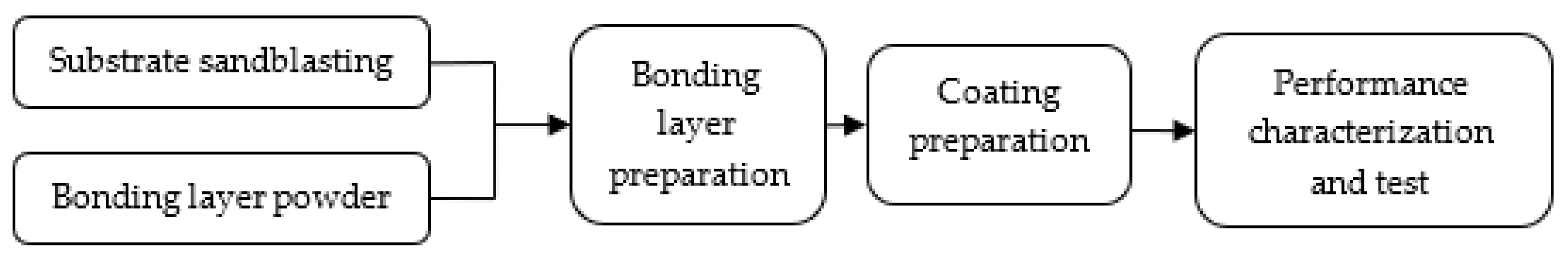
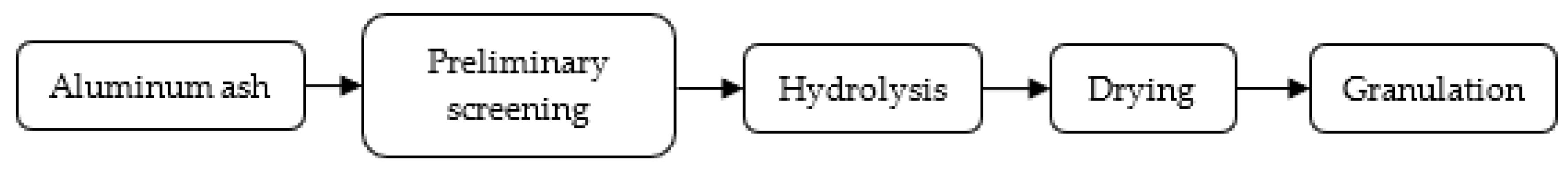
2.2. Preparation of Ultimate Spray Powder

The ultimate spray powder (USP) is made by UAA, while the UAA particles have different sizes and contain many impurities such as AlN and salt particles. Therefore, the UAA cannot be directly used for plasma spray and needs to be re-granulated. First, the UAA was screened by a 120-mesh standard sieve to remove the large impurities. Then, the aluminum ash was hydrolyzed in a constant temperature water bath (90–100 °C) for 3 h, and the ultra-pure water was generated by the Pure Water Meter (EPED-10TH type, produced by Nanjing Yipuda Technology Development Co., Ltd.). During the hydrolysis process, mechanical stirring was conducted to accelerate the chemical reaction. Next, the beaker was left to stand for 1 h, and we could see that the solution in the beaker had stratified, which is shown in Figure 2. The scum of upper layer and the turbid liquid of middle layer were filtered and dried in an oven (OHG type, produced by Shanghai Hecheng Instrument Manufacturing Co., Ltd.) with a constant temperature of 120 °C for 18–20 h. Then, the vibrating mill (MS-1 type, produced by Nanjing Heao Automation Technology Co., Ltd.) was used for ball milling and granulation, and the particle size of USP was kept at 120 to 200 mesh. The process flow of the preparation of USP is shown in Figure 3.

2.3. Preparation of Ultimate Coating

A moderate amount of the USP and the aluminum-clad nickel composite powder was taken into the powder feeder of the spray equipment. The 45-steel substrate was sandblasted by the sand blasting machine to roughen the surface and improve the bonding strength of the coating. After been sandblasted, the substrate was placed in a self-made mold for fixing an d supporting. Then, the Al–Ni alloy bonding layer was prepared on the surface of the substrate by the plasma spraying equipment. The process parameters are shown in Table 3.
After the preparation of the bonding layer, the spray parameters were readjusted to prepare an ultimate coating. As a new type of spray powder, there are currently no relevant spray process parameters for reference, so we designed an orthogonal experiment to obtain a set of optimized spray parameters. The orthogonal experiment consisted of four factors and three levels; a total of nine groups. The spray current, spray voltage, powder flow rate, and main air flow were selected as the key factors, and other influencing factors remained unchanged. The orthogonal experiment table is shown in Table 4, and the process flow of the ultimate coating preparation is shown in Figure 4.

2.4. Characterization and Test

The coating was prepared by the plasma spraying complete set of equipment, namely the FH-80 type, produced by China Shanghai Fahan Spraying Machinery Co., Ltd. The composition analysis was performed by X-ray fluorescence (XRF), which is the MiniPal4 type, produced by PANalytical Company. Phase analysis was performed by X-ray diffraction (XRD) analysis, the D/Max 2500PC Rigaku type, produced by Japan Science and Technology Co., Ltd. The microstructure of the coating was observed by scanning electron microscope (SEM), S-3400 type, produced by Hitachi, Ltd. Adhesive strength was tested by the mechanical test machine, CMT5105 type, produced by MTS Industrial Systems (China) Co., Ltd. Abrasion rate was measured by ring three-body abrasion tester, MMH-5 type, Jinan Hansen Precision Instrument Co., Ltd. The microhardness was measured by a digital microhardness tester, TMV-1 type, which was produced by Times Group. The porosity was measured by the Archimedes drainage method, and the experimental platform was self-made.
The diffraction pattern was obtained by Jade 6.0 and Orgin 9.1 analysis software. The flow properties of the USP were evaluated by the angle of repose, and it refers to GB/T11986-1989 “Measurement of surfactant powder and particle angle of repose”. The adhesive strength of the coating refers to GB/T8642-2002 “Thermal spray-determination of adhesive bond strength”.
The main parameters used to evaluate the performance of ultimate coating were porosity, adhesive strength, microhardness, and abrasion rate. According to the work of [23], the porosity can be measured by multiple methods, such as liquid intrusion, nondestructive testing, and image microscopic analysis. When the thermal spray method a is detonation gun, the porosity level is below 1%. However, in this experiment, we proposed a method for characterizing porosity from the side using water absorption. It is a simplified Archimedes drainage method, which is easy to operate, and the experimental results are convenient for calculation. The test piece of the coating was dried and weighed to obtain a mass m0, and then put in distilled water to get the mass of the discharged water m1. The test piece was removed from the water and weighed to obtain the mass m2. Finally, the porosity of the ultimate coating could be obtained according to the formula (m2m0)/m1. It can be seen from the formula that this method is different from the traditional porosity calculation method, so there are some differences in the calculation results. This method can qualitatively reflect the change trend of porosity; that is, the smaller the measured value, the denser the coating, which provides a basis for the optimization of spraying process parameters. According to the China national standard GB/T 8642-2002, the adhesive strength was measured by the stretching method. The equipment used was a universal mechanical testing machine, CMT5105 type, produced by Meters Industrial Systems (China) Co., Ltd. Owing to the thin thickness of the aluminum ash coating, the Vickers hardness tester was used to measure the hardness of ultimate coating. The 10 relatively smooth areas selected on the surface of the coating were tested and the results were averaged. Sandpaper was used as the grinding part to test the abrasion rate of the ultimate coating. The sample after abrasion was ultrasonically cleaned, dried, and weighed, and the abrasion rate was calculated according to the formula (m1m2)/t, where m1 is the mass before grinding, m2 is the mass after grinding, and t is the grinding time.

3. Results and Discussion

3.1. Characterization and Evaluation of Ultimate Spray Powder

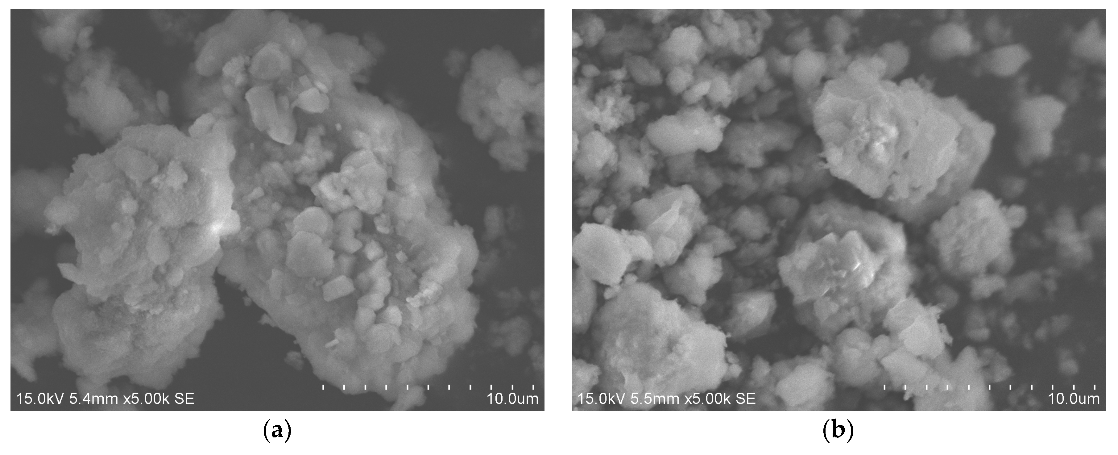
3.1.1. Observation and Analysis of Microstructure

The microstructure of the UAA and the USP was observed by SEM, and the results are shown in Figure 5. The particles of UAA can be observed from Figure 5a, which are agglomerated with a larger size, and its shape is approximately ellipsoidal. Figure 5b shows the SEM image of USP. After the USP is granulated by ball milling, the particles are relatively uniform with smaller size, and the shape is approximately spherical, which helps to improve the flowability of the spray powder and facilitate the preparation of ultimate coating.

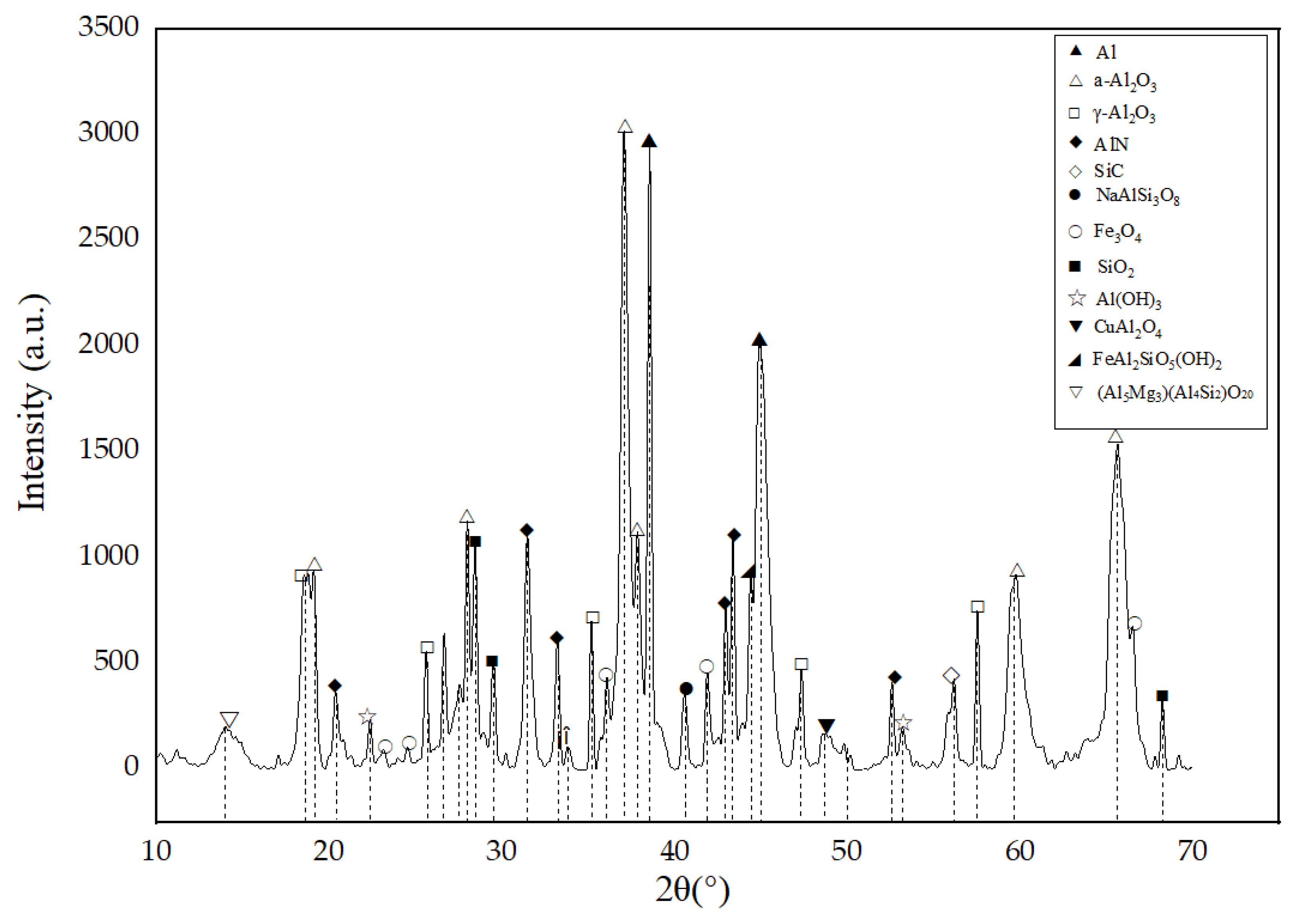
3.1.2. Composition Analysis

The chemical composition of the USP was analyzed by XRF. As shown in Table 5, owing to the screening of large particles during the ball milling and granulation process, the contents of N, Al, Fe, and other elements of the USP were generally decreased, but the type of element did not change.
According to the XRD pattern of the USP in Figure 6, it can be seen that the content of AlN and salt substances is greatly reduced. The salts’ substances are dissolved in water during the hydrolysis and are filtered off. AlN and H2O react to form Al(OH)3 and NH3. Moreover, the heating and stirring in a water bath accelerates the chemical reaction. After the NH3 overflows, the filtered Al(OH)3 is heated in the oven, and Al(OH)3 is further decomposed into Al2O3 and H2O. Therefore, the nitrogen content in USP is decreased.

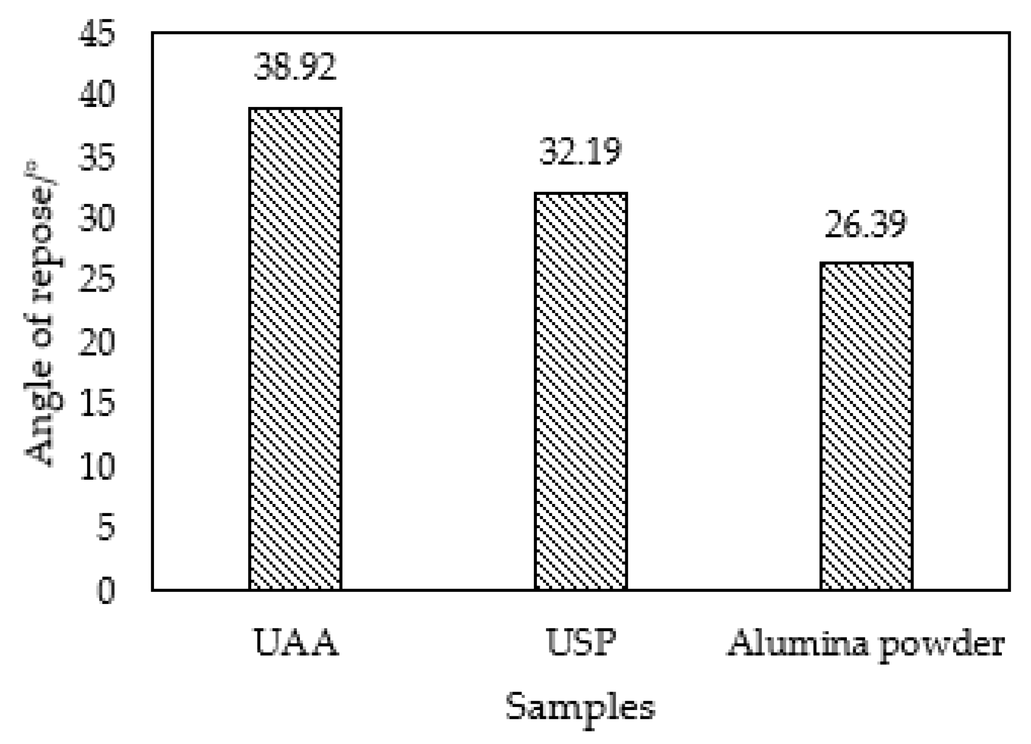
3.1.3. Evaluation of the Flowability

The angle of repose is measured in the state in which the gravity when the particles slide on the free slope of the volume layer of the powder pile and the friction between particles reach equilibrium and are at rest, which is the easiest way to check the flowability of the powder. The smaller the angle of repose, the smaller the friction and the better the flowability. According to China national standard GB/T11986-1989, an angle of repose of θ ≤ 40° can meet the needs of production flowability. The angle of repose of the different samples is shown in Figure 7. The angle of repose of the UAA is 38.92°, which is irregular granules and has poor flowability. After the ball milling and granulation, the angle of repose of the USP is reduced, which is 32.19°, and it belongs to regular granules with great flowability.

3.2. Effects of Spray Process on Coating Properties

3.2.1. Orthogonal Experiment

As a new type of coating, no relevant spray process parameters are available for reference. The spraying process has a great influence on the coating performance, while the spraying process contains multiple parameters and each parameter affects each other. An orthogonal experiment is an experimental method used to deal with multi-factor and multi-level design. The main tool of orthogonal experiment design is an orthogonal table. The tester can find the corresponding orthogonal table according to the number of factors and their levels. The tester performs experiments based on the orthogonal experimental table and obtains an optimal solution by analyzing the measurement results. The orthogonal experimental table is shown in Table 4. The spray current, spray voltage, powder flow rate, and main air flow are selected as the research variables. Other spraying process parameters such as spray distance (100 mm) and spray angle (60°) remain unchanged. The microhardness, adhesive strength, porosity, and abrasion rate of the coating were taken as survey indicators.
The influence degree of each index on the coating performance was analyzed, the multi-index comprehensive balance method was used to select the optimal parameters, and the comprehensive weighted score was used to evaluate the performance of the coating. First, assign weights to each indicator according to variable importance, then calculate the weighted indicators for each experiment, and turn it into a single indicator problem. Take a comprehensive score of 100 points, including microhardness, porosity, abrasion rate, and adhesive strength of 25 points each. The coating porosity and abrasion rate are negatively correlated with the coating quality, so they are negative. The microhardness, adhesive strength, porosity, and abrasion rate listed in Table 6 were measured by experimental calculations. In the lower half of Table 6, k1, k2, and k3 are the average values of the first, second, and third levels of the respective factors. R is the extreme difference (i.e., the difference between the maximum and minimum values in k1, k2, and k3), which reflects the influence degree of the listed factors on the investigation index of the sample, that is, the larger the R, the greater the influence of the listed factors on the investigation index.
According to the comprehensive scoring method, the primary and secondary factors affecting the spray performance of the UAA are spray current > spray voltage > powder flow rate > main air flow. When the spray current is 600 A, the spray voltage is 55 V, the powder flow rate is 24 g/min, and the main air flow is 33 lspm, the obtained coating performance is superior.

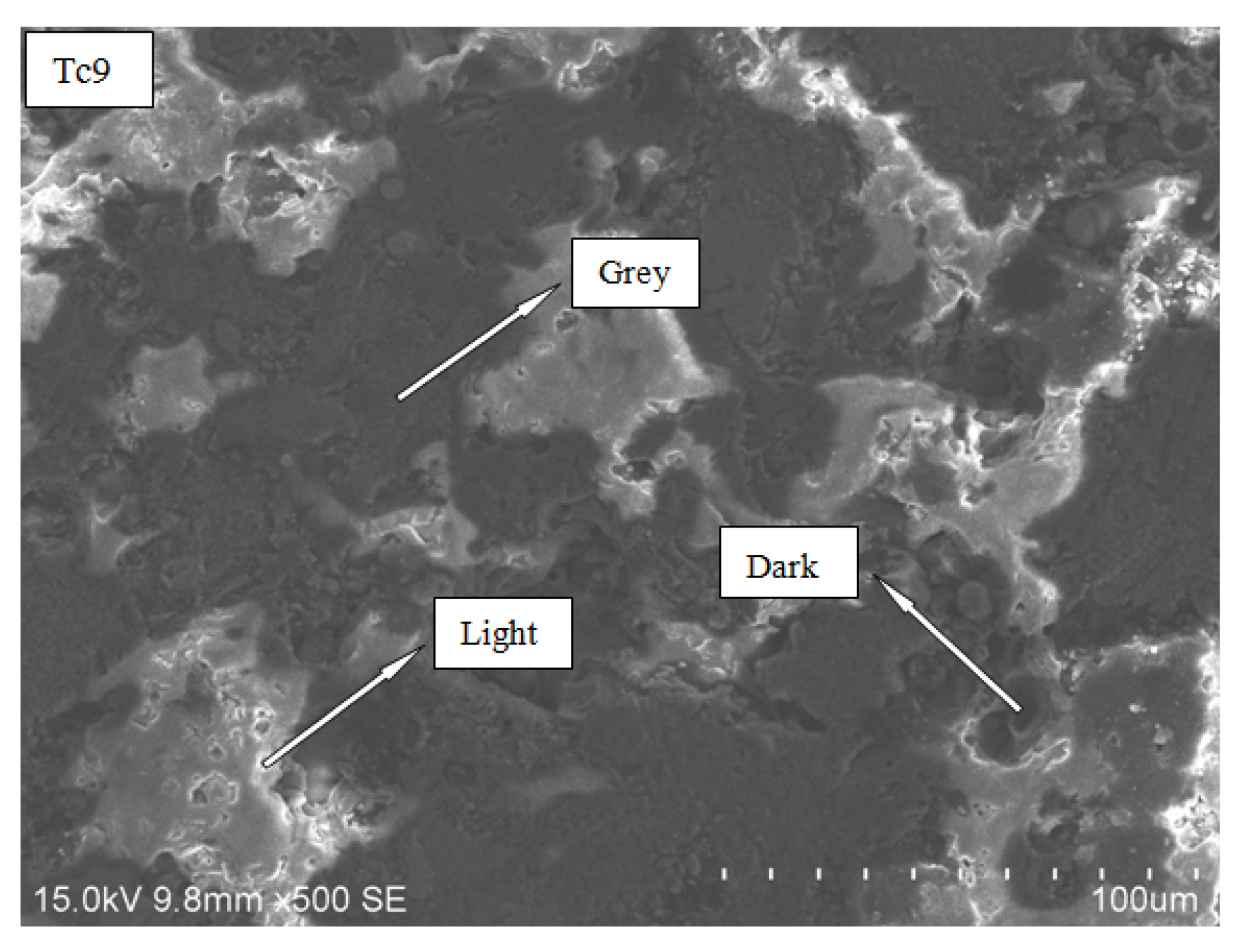
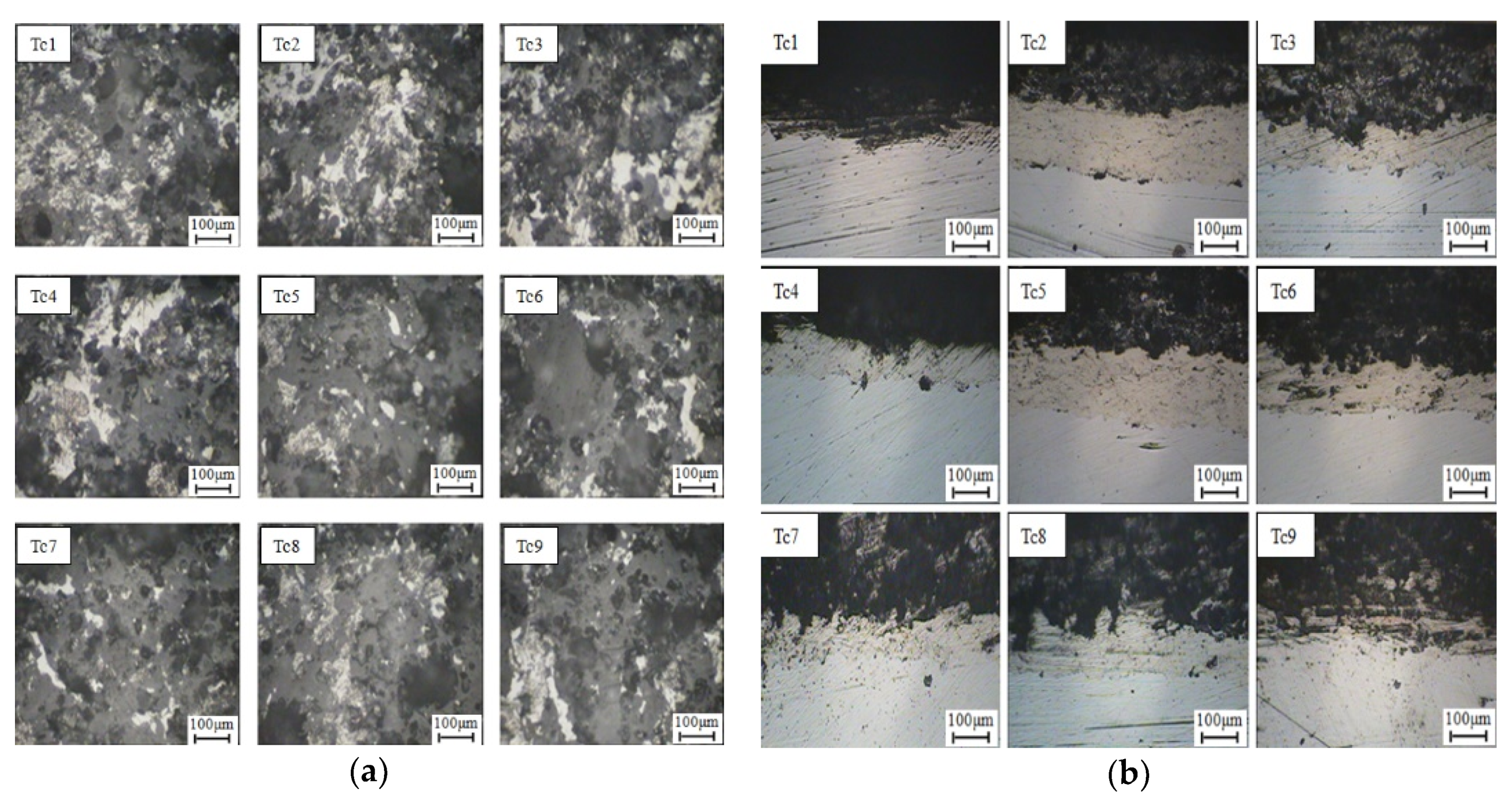
3.2.2. Microstructure of Coating

The microstructure of the ultimate coating was observed by SEM, and the results are shown in Figure 8. Figure 8a shows the surface microstructure of the coating. Under different spraying processes, there are different brightness areas on the surface of the coating. Figure 8b shows the section microstructure of the coating. The section is divided into three layers. The lower layer is the 45-steel substrate, the middle layer is the bonding layer, and the upper layer is the ultimate coating.

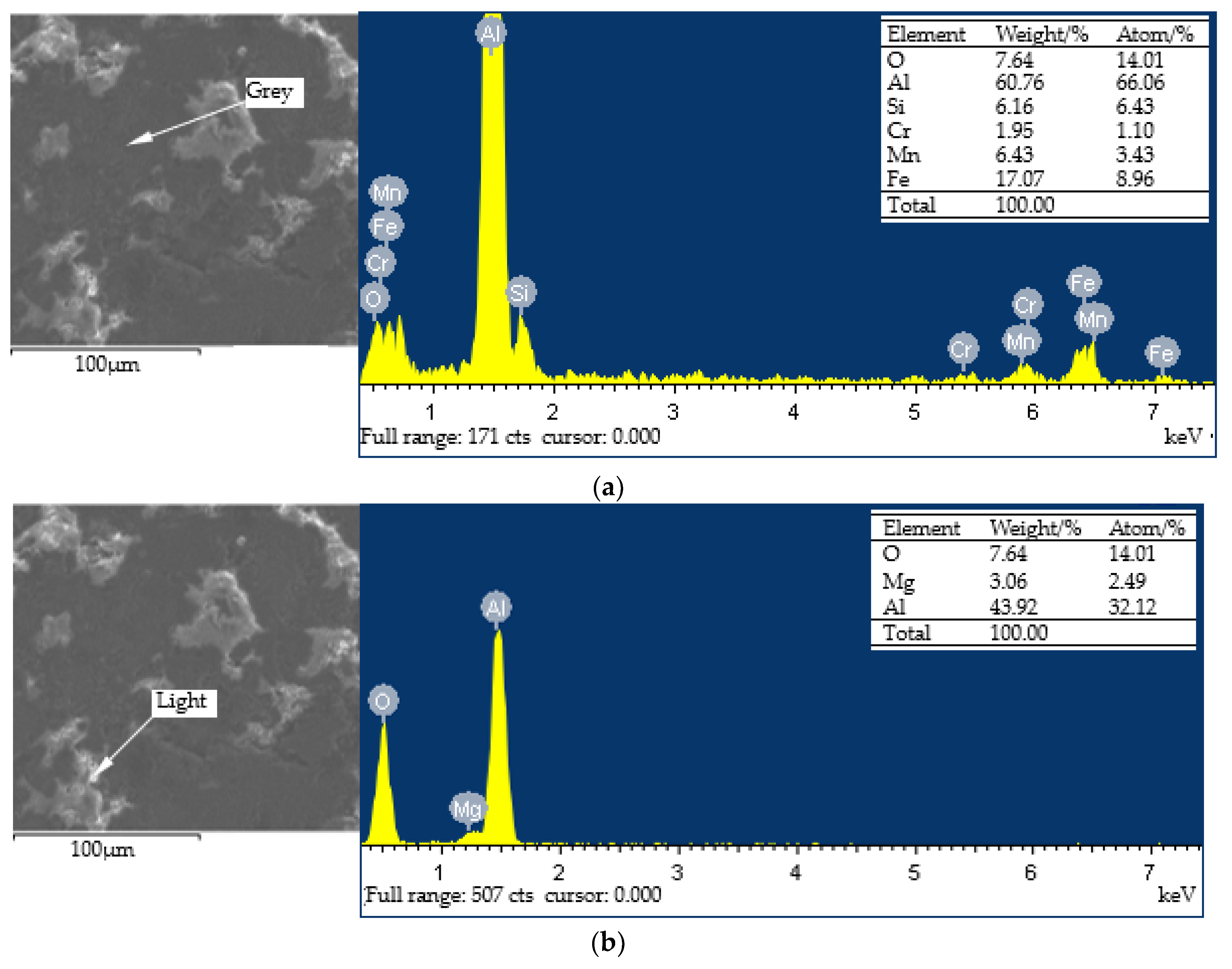
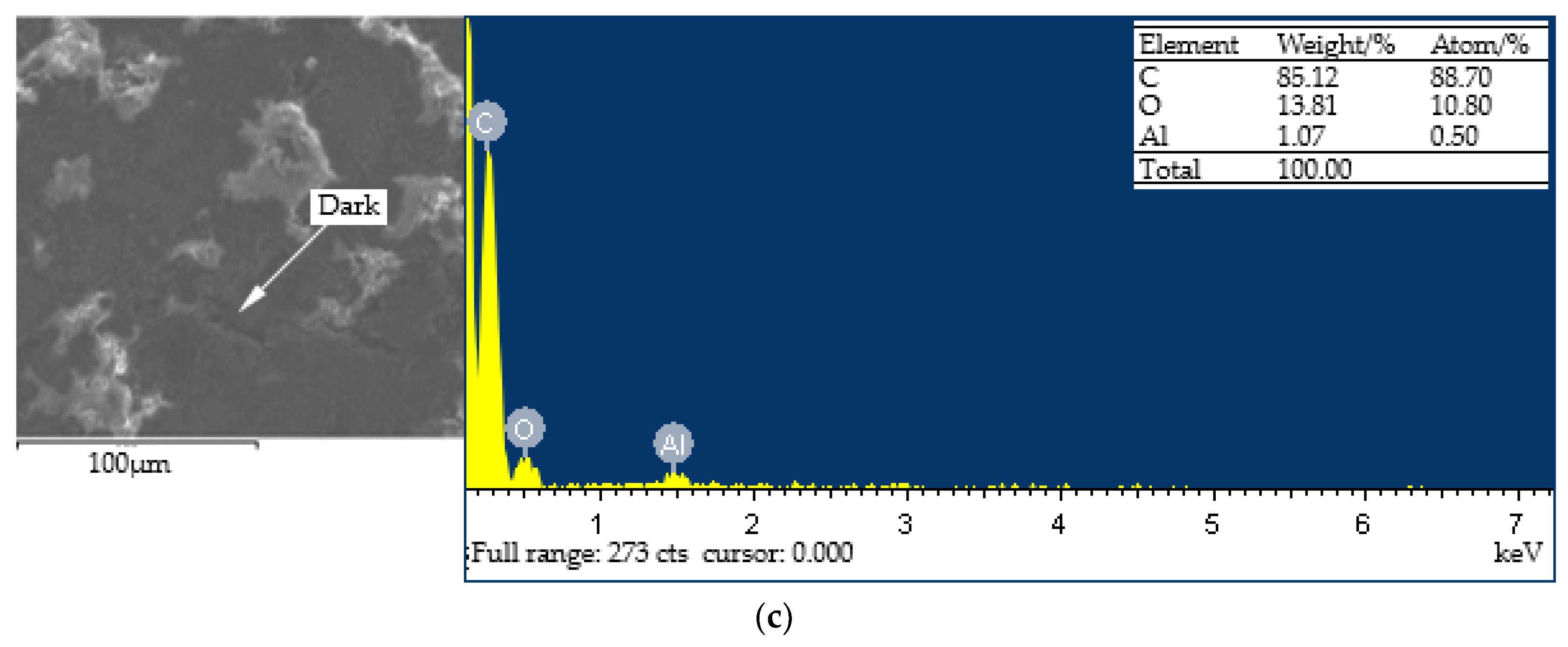
3.2.3. Energy Spectrum Analysis

As shown in Figure 9, there are different regions on the surface of the ultimate coating, which are divided into the gray region, light region, and dark region. The SEM and energy spectrum are applied for analysis.
The energy spectrum analysis was conducted by energy dispersive X-ray spectroscopy (EDS) to analyze the composition and content of different regions of the coating, and the analysis results are shown in Figure 10. Figure 10a shows the gray region. The region’s main elements are 60.6 wt.% Al and 6.2 wt.% Si, and the hardness is about 400–800 HV. Figure 10b shows a light region with 43.9 wt.% Al and 53.0 wt.% O. By preliminarily concluding, this region is dominated by alumina, and its hardness is about 500–900 HV. Figure 10c is a dark region comprising 85.1 wt.% C and 13.8 wt.% O, and it has a low hardness of about 100–200 HV. During the spraying process, the spraying direction is not perpendicular to the surface of the workpiece, and there is an angle of 60°. Therefore, the particle motion trajectory is similar to the parabolic shape. Under the action of deposition and gravity effects, particles of different masses are separated, while particles of similar mass produce agglomeration, leading to the difference in particle quality between different regions. The dark region contains a lot of carbon, about 85.1 wt.%, and the origin of carbon in the coating includes two primary aspects. First, the experimental raw materials come from electrolytic aluminum waste. In the process of electrolysis, the carbon reacts with alumina under the action of the current to form primary aluminum and carbon dioxide, thus some carbon remains in the aluminum ash. Second, from Figure 1, we can see that a certain amount of SiC is present in the ultimate aluminum ash. Under the high temperature of atmospheric plasma spraying, which will generate a high temperature above 2000 °C in the plasma arc outer flame, the SiC further reacts to form C and SiO2. Furthermore, under the action of spray angle and gravity, carbon is concentrated, and the dark region with a high carbon content is formed in the coating.

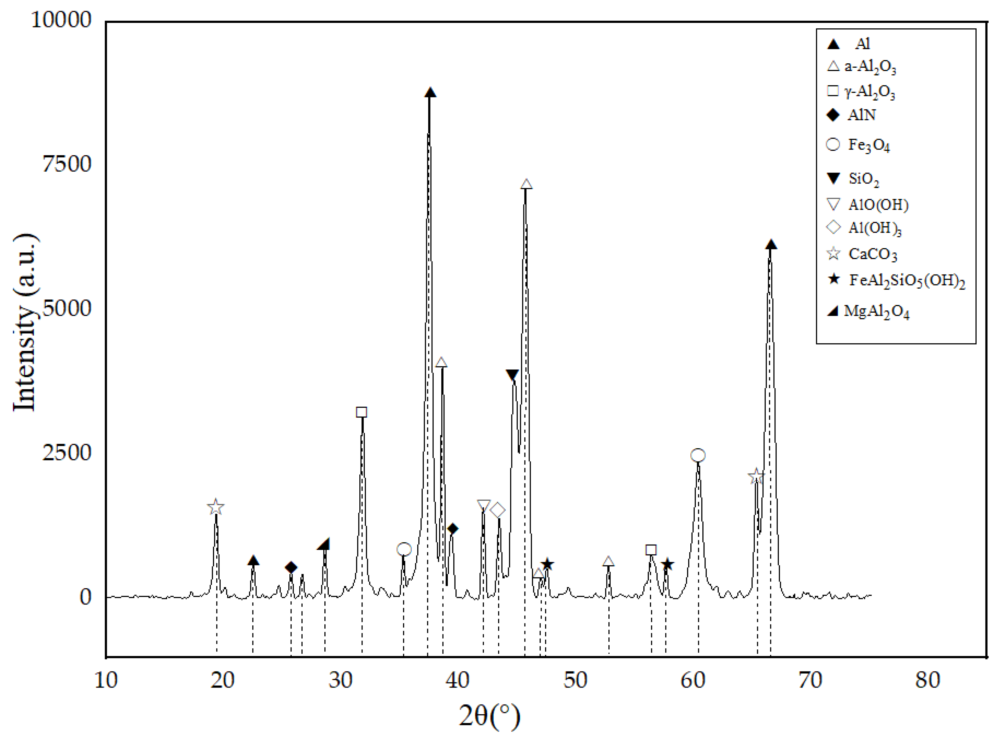
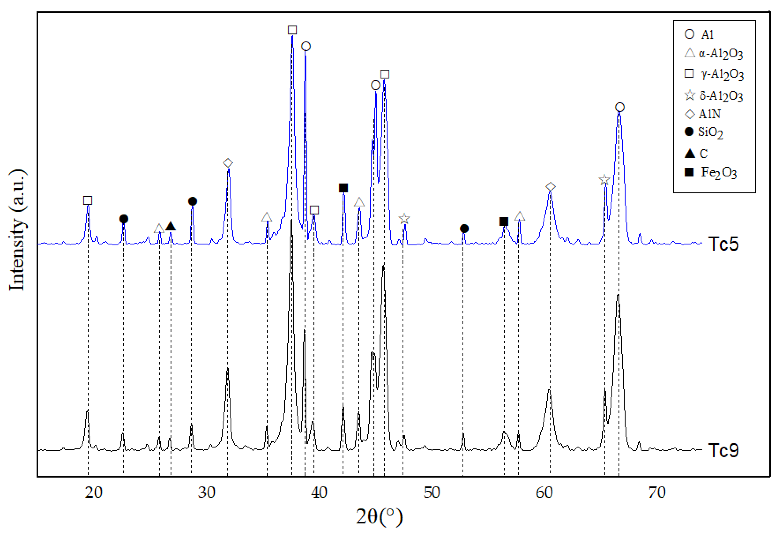
3.2.4. Phase Analysis

From the XRD pattern analysis of the ultimate coating of Figure 11, it can be concluded that the phase of the ultimate coating is greatly reduced. This is because, during the spray process, owing to the impact and collision of high-temperature and high-pressure plasma, the sublimation of salt substances occurs, and Al(OH)3, AlO(OH), and other substances undergo high-temperature decomposition reaction to form different forms of Al2O3. Furthermore, compared with the XRD pattern of the UAA, the phase of SiC disappeared, while the C and SiO2 still exist, which also shows from the side that the origin of carbon in the dark region is related to the chemical reaction decomposition of SiC. However, substances such as Al, AlN, and SiO2 still exist, and their influence on coating properties needs further exploration.

4. Conclusions

(1)
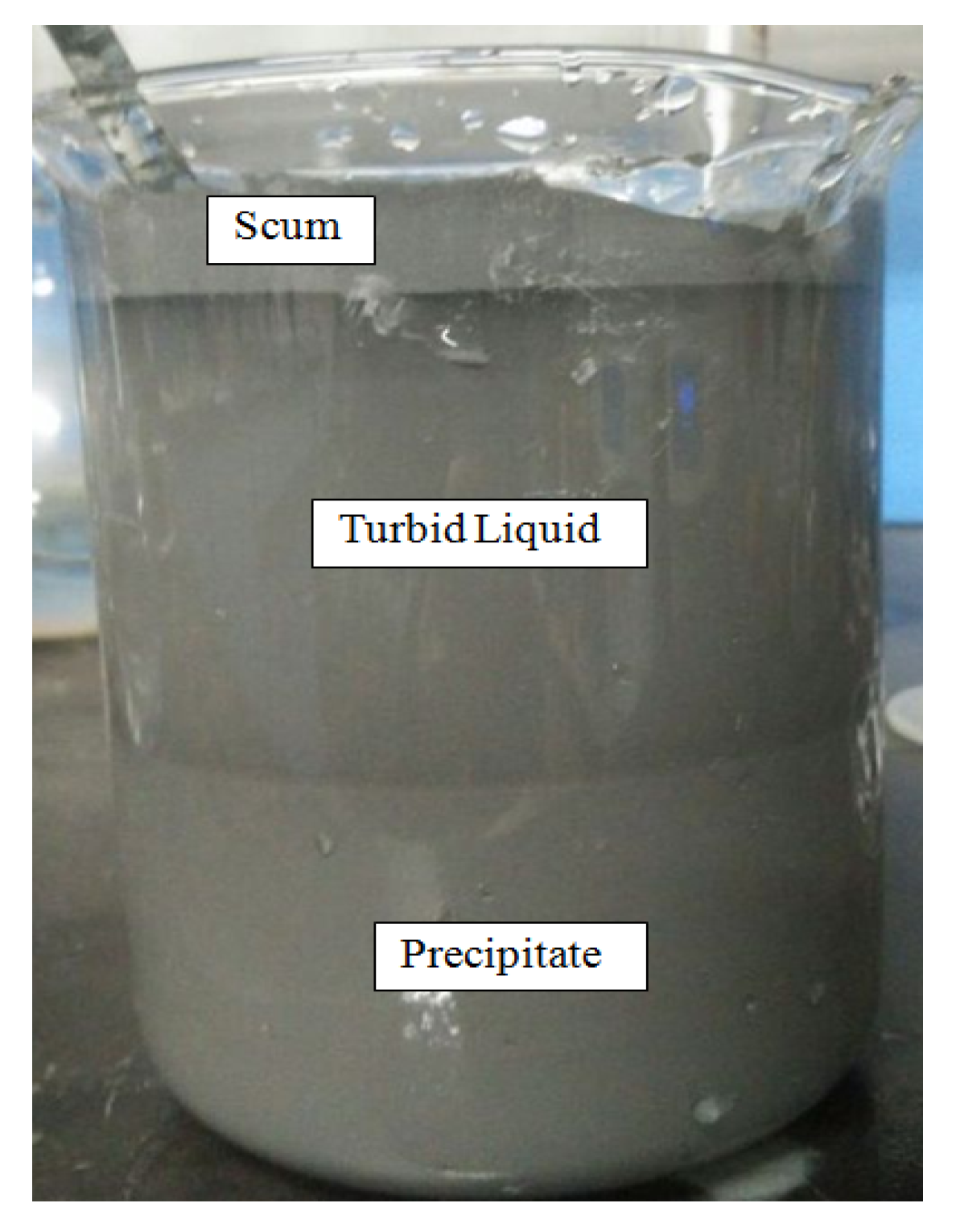
After hydrolysis and granulation of the UAA, the particle size becomes more uniform, and the impurities are significantly decreased. The angle of repose of prepared USP is 32.19° with great flowability, which meets the requirements of plasma spraying.
(2)
The primary and secondary order of the factors affecting the comprehensive performance of the ultimate coating is as follows: spray current > spray voltage > powder flow rate > main air flow. The preferred spraying parameters are as follows: spray current 600 A, spray voltage 55 V, powder flow rate 22 g/min, and main air flow 33 lspm. Also, the feasibility of preparing the coating based on the UAA was verified.
(3)
Different regions are formed on the surface of the ultimate coating. Among them, the bright and gray regions comprise more aluminum and oxygen elements, and the hardness is higher; the dark regions have higher carbon elements and lower hardness. Therefore, during the spray process, the formation of dark regions should be avoided in order to increase the hardness of the coating.
(4)
During the spray process, owing to the action of high temperature, some sodium salts undergo sublimation, and compounds such as Al(OH)3 and AlO(OH) undergo a chemical decomposition reaction. As a result, the type of the phase of the ultimate coating is reduced, and the characteristic peak of the diffraction pattern is less. However, substances such as Al, AlN, and SiO2 still exist, and their influence on coating properties needs further exploration. Besides, in the future, more spray process parameters can be taken into consideration to modify the orthogonal experiments and obtain a better spray solution.

5. Patents

The authors of this paper carried out research on the recycling and reuse of aluminum ash for many years. Three China invention patents related to this paper have been granted; the patent numbers are CN106830025B, CN106745618B, and CN106830035B.

Author Contributions

Conceptualization, N.H. and Z.Y.; methodology, L.S.; validation, Z.J. and G.T.; formal analysis, N.H. and L.S.; investigation, Z.J. and W.X.; resources, N.H. and L.S.; writing—original draft, Z.J.; writing—review and editing, N.H. and L.S.; visualization, Z.J.; supervision, N.H.

Funding

This research was supported by A Priority Academic Program Development of Jiangsu Higher Education Institutions (PAPD), Key Research and Development Program of Jiangsu (Industry Prospects and Common Key Technologies) (BE2018093).

Conflicts of Interest

The authors declare no conflict of interest.

References

  1. Wu, C.Y.; Yu, H.F.; Zhang, H.F. Extraction of aluminum by pressure acid-leaching method from coal fly ash. Trans. Nonferrous Met. Soc. China 2012, 22, 2282–2288. [Google Scholar] [CrossRef]
  2. Li, X.L.; Ou, Y.J.; Li, C.L.; Zhu, J.K.; Zhi, P.G. Preparation of Alumina from Aluminum Ash by Sintering with Sodium hydroxide. IOP Conf. Ser. Earth Environ. Sci. 2018, 233, 042027. [Google Scholar] [CrossRef]
  3. Aubert, J.E.; Husson, B.; Vaquier, A. Metallic aluminum in MSWI fly ash: Quantification and influence on the properties of cement-based products. Waste Manag. 2004, 24, 589–596. [Google Scholar] [CrossRef] [PubMed]
  4. Bai, Z.L.; Qin, B.K. Effect of Reaction Temperature on Silicon-Aluminum Alloy Prepared from Fly Ash. IOP Conf. Ser. Mater. Sci. Eng. 2019, 592, 012045. [Google Scholar] [CrossRef]
  5. Shusei, K.; Takeshi, H.; Tetsuya, M.; Kazuo, Y.; Motohide, M. Selective synthesis of zeolites A and X from two industrial wastes: Crushed stone powder and aluminum ash. J. Environ. Manag. 2019, 231, 749–756. [Google Scholar]
  6. Lisa, W.; Kristin, H.; Thomas, L. High cycle fatigue behavior of the severely plastically deformed 6082 aluminum alloy with an anodic and plasma electrolytic oxide coating. Surf. Coat. Technol. 2018, 349, 576–583. [Google Scholar]
  7. Abyzov, V.A. Refractory Cellular Concrete Based on Phosphate Binder from Waste of Production and Recycling of Aluminum. Procedia Eng. 2017, 206, 783–789. [Google Scholar] [CrossRef]
  8. Abyzov, V.A. Lightweight Refractory Concrete Based on Aluminum-Magnesium-Phosphate Binder. Procedia Eng. 2016, 150, 1440–1445. [Google Scholar] [CrossRef]
  9. Zhan, D.P.; Zhang, H.S.; Jiang, Z.H. Effects of AIMnCa and AIMnFe Alloys on Deoxidization of Low Carbon and Low Silicon Aluminum Killed Steels. J. Iron Steel Res. Int. 2008, 15, 15–18. [Google Scholar] [CrossRef]
  10. Zhang, G.H.; Chou, K.C. Deoxidation of Molten Steel by Aluminum. J. Iron Steel Res. Int. 2015, 22, 905–908. [Google Scholar] [CrossRef]
  11. Peng, H.L.; Zhong, S.X.; Xiang, J.X.; Lin, Q.T.; Yao, C.; Dong, J.H.; Yin, G.C.; Yao, K.; Zeng, S.Y.; Zhong, J. Characterization and secondary sludge dewatering performance of a novel combined aluminum-ferrous-starch flocculant (CAFS). Chem. Eng. Sci. 2017, 173, 335–345. [Google Scholar] [CrossRef]
  12. Lin, Q.T.; Peng, H.L.; Zhong, S.X.; Xiang, J.X. Synthesis, characterization, and secondary sludge dewatering performance of a novel combined silicon–aluminum–iron–starch flocculant. J. Hazard. Mater. 2015, 285, 199–206. [Google Scholar] [CrossRef] [PubMed]
  13. Kachalova, G.S. Modern coagulants and flocculants in the cleaning of washing waters of water treatment plants. IOP Conf. Ser. Mater. Sci. Eng. 2018, 451, 012226. [Google Scholar] [CrossRef]
  14. Tripathy, A.K.; Mahalik, S.; Sarangi, C.K.; Tripathy, B.C.; Sanjay, K.; Bhattacharya, I.N. A pyro-hydrometallurgical process for the recovery of alumina from waste aluminium dross. Miner. Eng. 2019, 137, 181–186. [Google Scholar] [CrossRef]
  15. Parvati, R.; Shravan, R.; Sushmit, B.; Sylvester, A.G. Synthesis of high temperature (1150 °C) resistant materials after extraction of oxides of Al and Mg from Aluminum dross. Mater. Today Proc. 2019. [Google Scholar] [CrossRef]
  16. Leiva, C.; Galiano, Y.L.; Arenas, C.; Fariñas, B.A.; Pereira, F. A porous geopolymer based on aluminum-waste with acoustic properties. Waste Manag. 2019, 95, 504–512. [Google Scholar] [CrossRef]
  17. Dirisu, J.O.; Fayomi, O.S.I.; Oyedepo, S.O.; Jolayemi, K.J.; Moboluwarin, D.M. Critical evaluation of aluminium dross composites and other potential building ceiling materials. Procedia Manuf. 2019, 35, 1205–1210. [Google Scholar] [CrossRef]
  18. Victor, E.I.; Fernando, E.I.; Carlos, R.M. Ceramic panels versus aluminium in buildings: Energy consumption and environmental impact assessment with a new methodology. Procedia Manuf. 2019, 233, 959–974. [Google Scholar]
  19. Sobolev, A.; Kossenko, A.; Zinigrad, M.; Borodianskiy, K. An investigation of oxide coating synthesized on an aluminum alloy by plasma electrolytic oxidation in molten salt. Appl. Sci. 2017, 7, 889. [Google Scholar] [CrossRef]
  20. Takajo, S.; Hollis, K.J.; Cummins, D.R.; Tegtmeier, E.L.; Dombrowski, D.E.; Vogel, S.C. Texture evolution in U-10Mo nuclear fuel foils during plasma spray coating with Zr. Quantum Beam Sci. 2018, 2, 12. [Google Scholar] [CrossRef]
  21. Rahmati, M.; Raeissi, K.; Toroghinejad, M.R.; Hakimizad, A.; Santamaria, M. Effect of pulse current mode on microstructure, composition and corrosion performance of the coatings produced by plasma electrolytic oxidation on AZ31 Mg alloy. Coatings 2019, 9, 688. [Google Scholar] [CrossRef]
  22. Kolås, T.; Røyset, A.; Grandcolas, M.; Cate, M.T.; Lacau, A. Cool coatings with high near infrared transmittance for coil coated aluminium. Sol. Energy Mater. Sol. Cells 2019, 196, 94–104. [Google Scholar] [CrossRef]
  23. John, G.O.; Li, W.G.; Zhao, Y.T.; Li, C.L. Porosity and its significance in plasma-sprayed coatings. Coatings 2019, 9, 460. [Google Scholar]
Figure 1. X-ray diffraction (XRD) pattern of ultimate aluminum ash.
Applsci 09 04980 g001
Figure 2. The stratification after hydrolysis.
Applsci 09 04980 g002
Figure 3. The process flow of the ultimate spray powder (USP) preparation.
Applsci 09 04980 g003
Figure 4. Process flow of the ultimate coating preparation.
Applsci 09 04980 g004
Figure 5. Scanning electron microscope (SEM) images: (a) ultimate aluminum ash; (b) ultimate spray powder.
Applsci 09 04980 g005
Figure 6. The X-ray diffraction (XRD) pattern of ultimate spray powder.
Applsci 09 04980 g006
Figure 7. Angle of repose of different samples. UAA, ultimate aluminum ash.
Applsci 09 04980 g007
Figure 8. Metallographic photomicrograph: (a) surface microstructure of the coating; (b) section microstructure of the coating.
Applsci 09 04980 g008
Figure 9. SEM images of coating numbered 9.
Applsci 09 04980 g009
Figure 10. Energy dispersive X-ray spectroscopy (EDS) images of ultimate coating: (a) grey region; (b) light region; (c) dark region.
Applsci 09 04980 g010aApplsci 09 04980 g010b
Figure 11. XRD pattern of ultimate coating.
Applsci 09 04980 g011
Table 1. Chemical components of ultimate aluminum ash (UAA).
ElementAlFeCaSiNTiZnClMnOthers
Wt.%54.214.87.73.93.83.32.52.11.66.1
Table 2. Phase composition of ultimate aluminum ash.
Molecular FormulaAlAl2O3AlNAlO(OH)SiO2Others
Semi-quantitative (%)5 ± 220 ± 222 ± 23 ± 1149 ± 3
Table 3. The spray process parameters of bonding layer.
PowderSpray Current/ASpray Voltage/VMain air Flow/slpmPowder Flow Rate/g·min−1
Al/Ni550553324
Table 4. The factors and their levels for L9 (34) orthogonal experiment.
LevelsFactors
A
Spray Voltage/V
B
Spray Current/A
C
Powder Flow Rate/g·min−1
D
Main Air Flow/Slpm
1505002230
2555502433
3606002636
Table 5. The X-ray fluorescence (XRF) analysis results of ultimate spray powder.
ElementAlFeCaSiNTiZnCl
Wt.%51.814.76.03.70.82.72.23.5
Table 6. The results of the orthogonal experiment.
No.ABCDMicrohardness/HVPorosity/%Abrasion Rate 10−3 g/minAdhesive Strength/MPaComprehensive Score
1111193.440.1532.48−66.15
21222370.920.1811.25−45.2
31333377.180.1720.025−51.53
42123382.960.1520.243−48.41
52231654.870.2312.4412−39.33
62312599.570.169.7116−10.52
73132607.290.2020.716−50.44
83213688.830.1525.885−38.65
93321623.710.1614.1519−9.71
k1−54.30−55.00−38.44−38.40
k2−32.76−41.06−34.44−35.39
k3−32.94−23.92−47.10−46.20
R21.5431.0812.6610.81
Factors primary to secondaryB > A > C > D
Preferred schemeB3A2C2D2

