Article

The Effect on Bone Stress in Oral Prosthetic Rehabilitation Supported by Different Number of Dental Implants: A Numerical Analysis

by
María Prados-Privado
1,2,†,
Sergio A. Gehrke
3,*,†,
Lúcia Kurokawa Tozaki
4,
Luiz Carlos Silveira Zanatta
4,
Paulo Cruz
4,
Patricia Mazon
5,
Piedad N. De Aza
6 and
Juan Carlos Prados-Frutos
7
1
Department Continuum Mechanics and Structural Analysis, Higher Polytechnic School, Carlos III University, Avenida de la Universidad 30, Leganés, 28911 Madrid, Spain
2
Research Department, ASISA Dental, Calle José Abascal 32, 28003 Madrid, Spain
3
Department of Research, Biotecnos, Cuareim 1483, Montevideo CP 11100, Uruguay
4
Department of Implantology, Universidade Paulista, 01310-100 São Paulo, Brazil
5
Departamento de Materiales, Óptica y Tecnologia Electrónica, Universidad Miguel Hernández, Avda. Universidad s/n, 03202 Elche (Alicante), Spain
6
Instituto de Bioingenieria, Universidad Miguel Hernández, Avda. Ferrocarril s/n. Elche, 03202 Alicante, Spain
7
Department of Medicine and Surgery, Faculty of Health Sciences, Rey Juan Carlos University, Avenida de Atenas s/n, Alcorcón, 28922 Madrid, Spain
*
Author to whom correspondence should be addressed.
Equal contribution.
Appl. Sci. 2019, 9(22), 4920; https://doi.org/10.3390/app9224920
Submission received: 11 October 2019 / Revised: 6 November 2019 / Accepted: 12 November 2019 / Published: 15 November 2019
(This article belongs to the Special Issue Current Trends in Biomaterial Scaffolds)

Abstract

:
The aim of this study was to compare the mechanical behavior of two types of prosthesis as well as the stress distribution on the prostheses’ components and the bone. Two groups were analyzed: in the first group (M1), the prothesis was composed of two implants placed at a distance of 14 mm; in the second group (M2), the prothesis was composed of three implants installed at a distance of 9.7 mm from each other. An axial load of 100 N distributed on the cantilever throughout the region from the distal implant and a 30 N axial load on the implants in the inter-foramen region, were applied in both model 1 and model 2. In both models, the stress was concentrated in the region near the neck of the implant, resulting in a maximum value of 143 MPa in M1 and of 131MPa in M2. In M1, the stress along the bone varied from of −4.7 MPa to 13.57 MPa, whereas in M2, it varied from −10 to 12 MPa. According to the results obtained, the model corresponding to six implants presented a better distribution of bone stress around the implants.

1. Introduction

In fully edentulous patients who do not adapt to the use of mandibular total prostheses, the widely accepted clinical solution is a prosthesis supported by four to six implants placed in the interphalangeal region, which demonstrates according to both clinical accompaniment and in vitro analysis, high success rates [1,2,3].
Factors such as mandibular curvature, cortical and trabecular bone density, length and number of implants, surface, cantilever length, and stiffness of the metal structure have great influence on the distribution of stresses to the bone tissue and have been the subject of many studies. Failure prevention requires testing and stress analysis in vitro as well as in vivo [4,5].
Detecting stress on implant-supported prostheses and analyzing its distribution to the implants have a fundamental importance for the evaluation of both the stresses applied on the implants and the design of the structure. It is important to evaluate different stresses generated on the implants by different loads [6,7].
The evolution of science and technology has motivated the realization of simulations and mechanical analysis of biological structures by advanced computational systems. The finite element method (FEM) is an analytical technique that currently represents one of the most complete computational tools for the study of stress distribution in dentistry.
This study analyzed, using the finite element method, the importance of the number of implants in the stress distribution transmitted to the implants and to the supporting bone tissue. The stresses generated in this type of rehabilitation were also evaluated and compared.

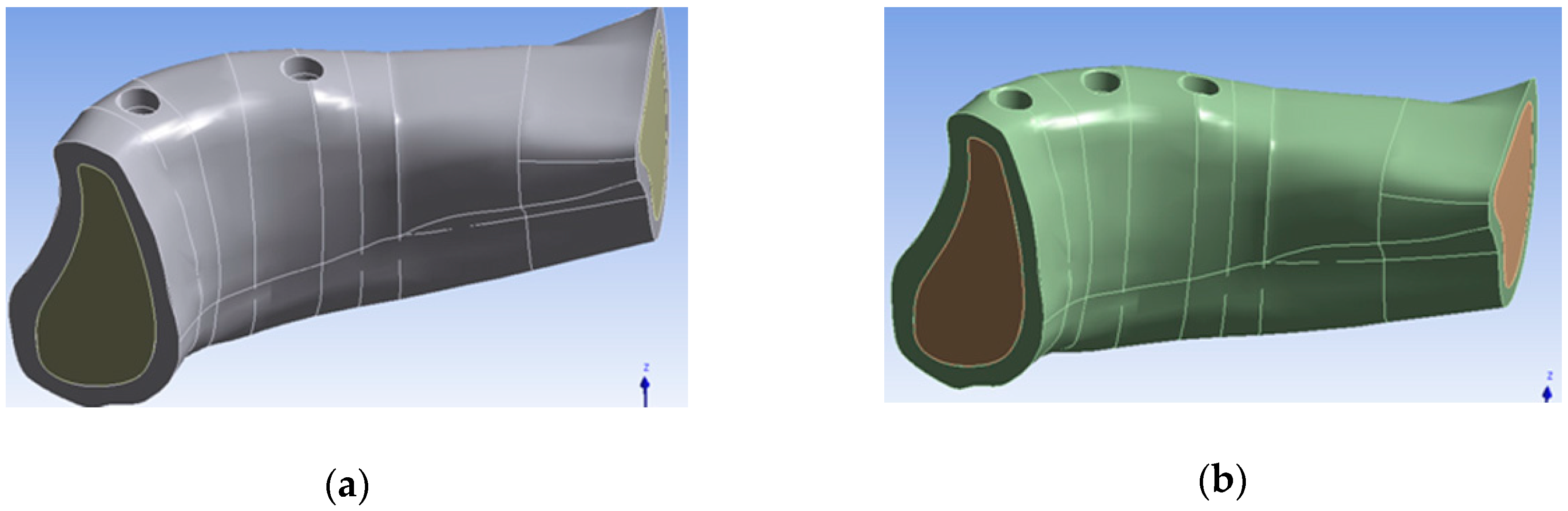
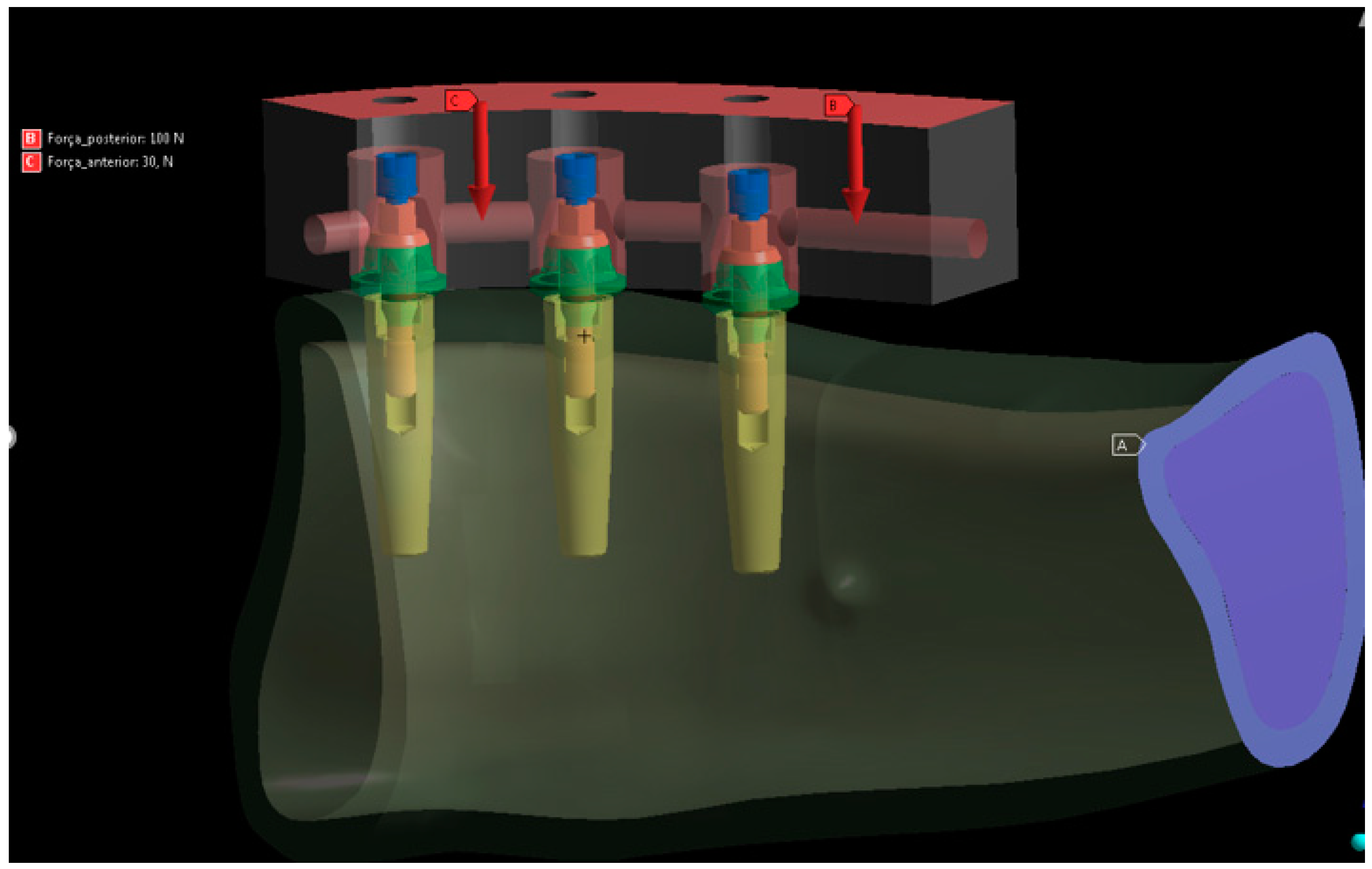
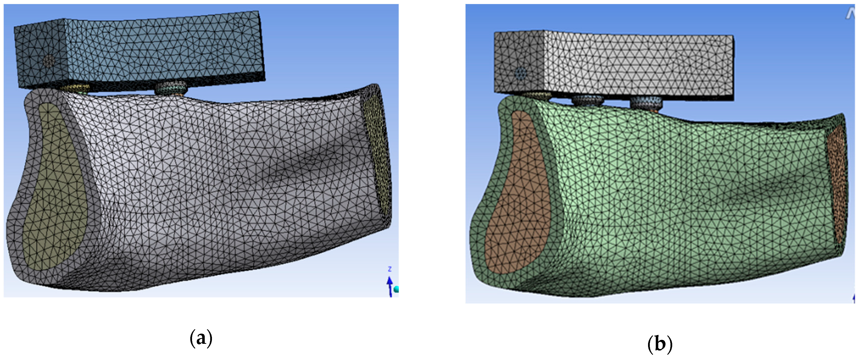
2. Materials and Methods

The three-dimensional models were composed of a human mandible, implants, and their prosthetic components. The human mandible was obtained from the Renato Archer Information Technology Center database (Campinas, SP, Brazil), and the Rhinoceros 4.0 NURBS Modeling for Windows program (Robert McNell & Associates, Seattle, WA) was used for the construction of two three-dimensional models. The images in the CTI database, acquired from computerized tomographies, were previously approved by the Ethics Committee (#183/2015 (10 April 2015)).
Two groups were analyzed: in the first group (M1), two implants were implanted in the inter-foramen region separated from each other by 14 mm. The second group (M2) was composed of three implants placed at a distance of 9.7 mm from each other. On the implants in both groups were installed aesthetic conical abutments and a metallic crown in NiCr.
Figure 1 details the mandible with the holes where the implants were placed in each model.
The implant employed in this study was an internal conical hexagon, 13 mm of length and 3.5 mm of diameter, while the aesthetic conical abutment had a length of 1 mm; both were manufactured by Implacil De Bortoli (São Paulo, SP, Brazil).
To simulate teeth, an acrylic resin platform was developed, which was used to apply the loads on the model. The assembly of the model was done on Biocad Philosophy, simplifying the morphology of the mandible (Figure 2).
Regarding the bar, the height was 7 mm, with a cantilever length of 14 mm. The assembly of both models were exported to ANSYS software version 12.1 (Houston, USA). The material properties employed are detailed in Table 1 [8].
A complete osseointegration was added to both the trabecular and the cortical bone with the implant [9]. The models were subjected to an axial load of 100 N distributed throughout the region on the cantilever from the distal implant with reference to the midline and to a 30 N axial load on the implants in the inter-foramen region, both in model 1 and in model 2, as shown in Figure 3 [10,11].
A symmetry in the median sagittal plane and a fixed support in the posterior surface were considered as boundary conditions in both models.
Tetrahedral elements with 10 nodes were employed in both models (Figure 4); we obtained the following elements and nodes for models 1 and 2, respectively: 106218 and 116688 elements; 170513 and 189695 nodes.

3. Results

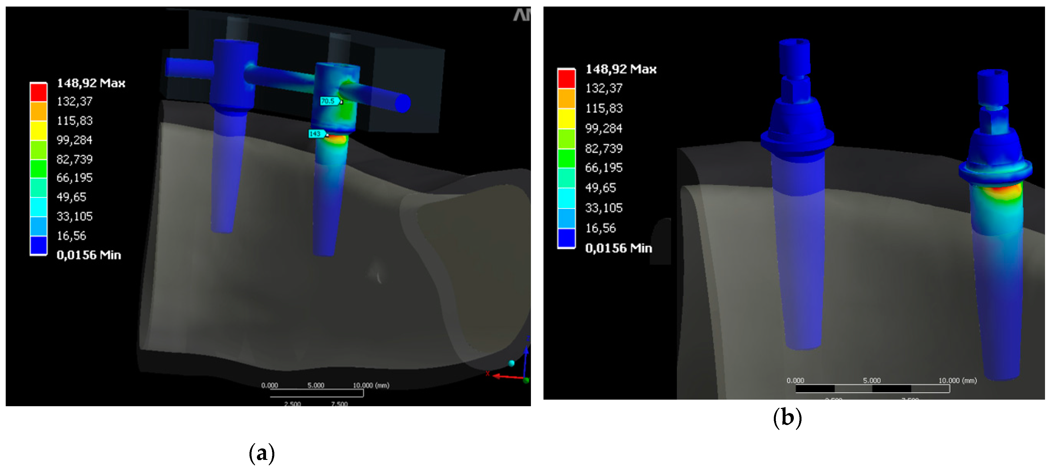
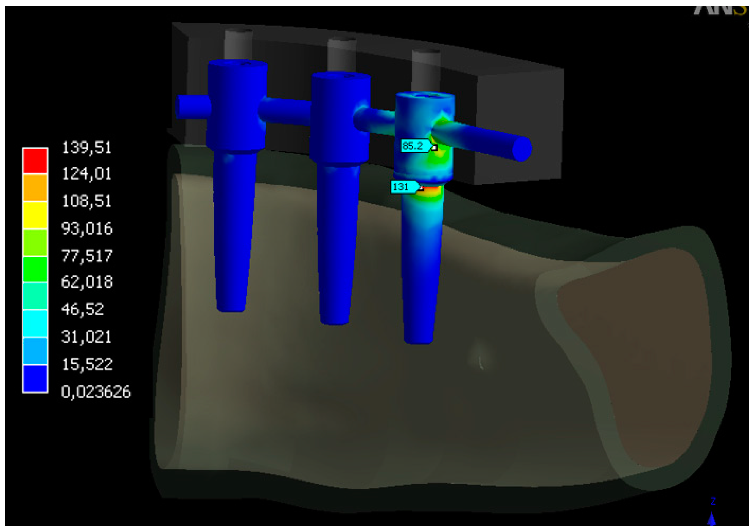
3.1. Distribution Stress in Dental Implants

In the M1 group, corresponding to four implants, the highest values of von Mises stress appeared around the bar where the implants were more rigid. The maximum stress on the implant was 148.92 MPa, while that on the bar was 70.5 MPa, as detailed in Figure 5.
In the M2 group, as shown in Figure 6, the highest von Mises stresses appeared in the more distal implant, with the same distribution as in group M1. Regarding to the metallic structure, the highest stress appeared in the cantilever region, specifically at the fixation point of the metallic structure on the most distal implant, while a low level of stress was recorded in the anterior region. Analyzing the implants in both groups, the distal implant showed a greater stress in comparison with the other implants.

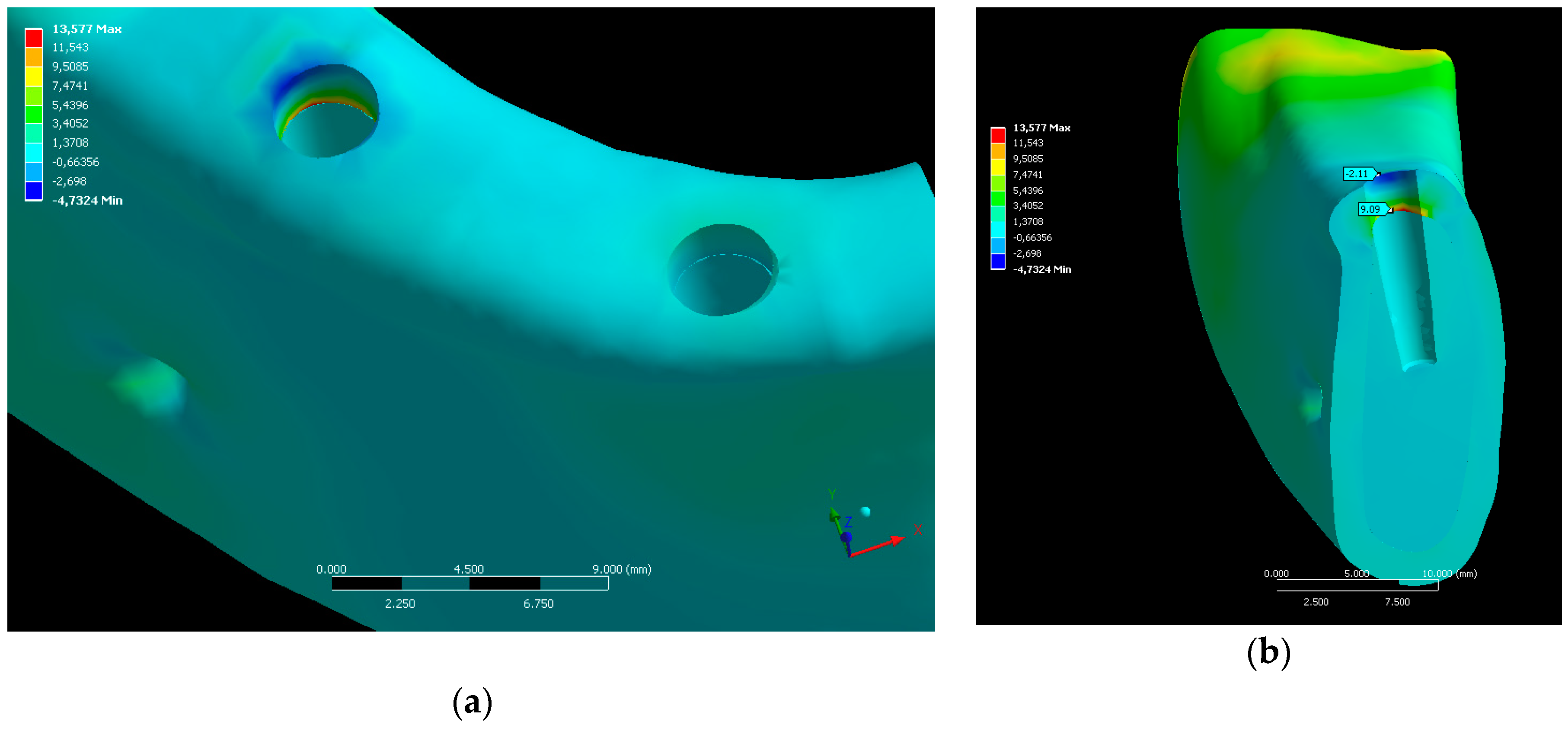
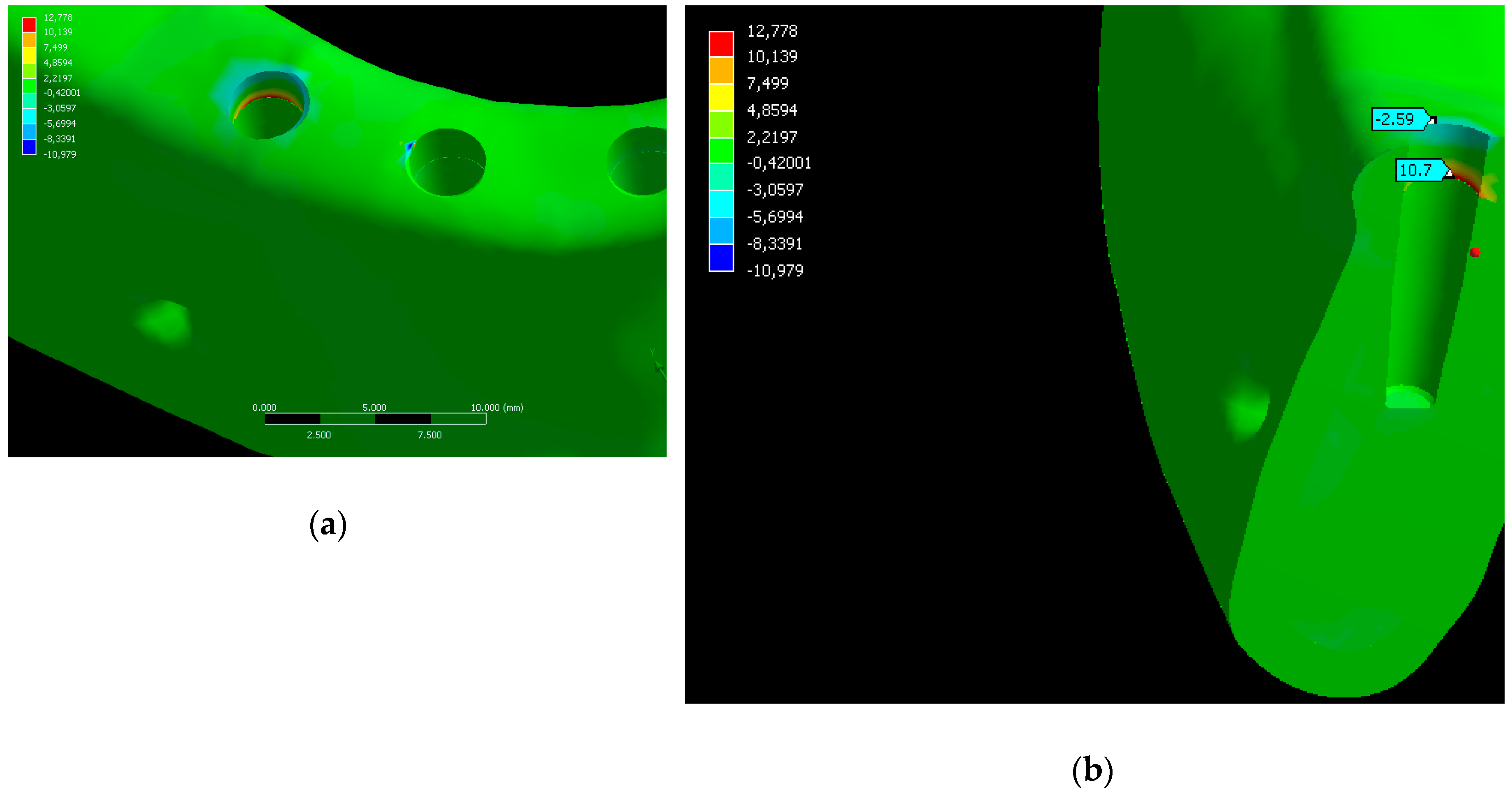
3.2. Distribution Stress in Bone

The maximum principal stresses were obtained on the bone. As Figure 7 details, the area corresponding to the distal implant presented a compression of −4.7 MPa. These forces were more evident in the portion corresponding to the cortical bone (Figure 7).
In M2, the maximum compression principal stress on the bone was −3.05MPa and it appeared at the most distal edge of the hole corresponding to the most distal implant. A compression stress of −0.42 MPa appeared in the second hole, and considering a perpendicular cut, a compression stress that concentrated on the cortical bone and a small traction toward the trabecular bone appeared in the most distal hole, as Figure 8 details.
Table 2 reports the stress obtained in each group and the percentage difference between them.

4. Discussion

This finite element study analyzed the effect of the number of implants on the distribution of stress transmitted to the implants and to the supporting bone tissue and the stress obtained in different types of rehabilitation.
Three-dimensional finite element analysis has proven to be the ideal technique for stress, deformation, and structural displacement analyses, enabling more accurate simulations without being an invasive technique [12]. We initially tried to generate a tridimensional geometric model of the object to be studied as faithful as possible, in order to obtain the most reliable results.
However, there are limitations in this kind of studies. First of all, bone is a complex structure without definite patterns and has distinctive characteristics in each person; therefore, its geometry does not have defined properties. Also, the model corresponded to only one half of the mandible which did not compromise the study. Finally, all materials were modelled as linear, elastic, isotropic, and homogeneous. These assumptions have been accepted and verified in several studies [13,14].
Meijer and Liu concluded that it is not necessary to construct a model of the entire mandible in order to compare the distribution of stress around implants [15,16]. This simplification has the advantage of reducing the modeling time of the structure and the computational cost.
Although some authors [17,18,19] report that the stress values found in their work are smaller than the fracture limits of materials such as bone and titanium, these statements must be made with some warnings so that they can be translated to the clinical field, since the simplifications assumed in the models can generate values that do not correspond to real clinical situations. In this study, in both models, the highest values of the stress for both compression (4.7 MPa in M1 and 3.05 MPa in M2) and traction (9.09 MPa in M1 and 10.7 MPa in M2) on the cortical bone did not exceed the maximum limits of physiological stress which the bone can support, corroborating other scientific studies [20], according to which when the maximum main compression stress exceeds 170–190 MPa and the main tensile stress exceeds 100–130 MPa bone fracture and/or the onset of bone resorption occur.
Regardless of the number of implants, it was observed that the maximum stress occurred on the surface of the cortical bone near the cervical area of the most distal implant, corroborating several results found by other studies [16,21]. The maximum stress values at the border between the cortical bone and the trabecular bone were evident during the study, demonstrating the difference in mechanical resistance between the two bones, agreeing with Reference [22]. There was compression stress across the surface of the implant, but it virtually disappeared when compared to the compression effect on the outermost surface of the cortical bone and traction on the border between the cortical and the trabecular bone. The stress was shown to be much more evident in the cortical bone because it had greater mechanical resistance and greater modulus of elasticity, and thus was able to accumulate greater stress, a conclusion similar to that of another study [23]. We measured a great difference between the compression stresses on the surface of the cortical bone in the distal region of the distal implants in the two models studied. The difference indicated a 54.69% higher compression stresses in model 1, a result similar to that of another study [24]. However, once again, considering the physiological limit acceptable for the bone, the compression stresses in both models were quite small, being −3.05 MPa (model 2) and −4.73 (model 1), and thus acceptable in both situations.
Regarding the number of implants, in both models, the stress was concentrated in the region near the neck of the implant. In model 1, a stress of 143 MPa was observed, whereas in model 2, a stress of 131 MPa was measured, indicating a difference of 6.74%, very small in quantitative terms because Model 1 had two implants less than Model 2. Just as in this work, Davis et al. [25] demonstrated that the increase of only one implant over five supporting a prosthesis did not result in a significant impact on the load supported by the implant closer to the force application.
The maximum stresses on the implant appeared near the end in its distal area in both models, in agreement with several finite element studies [16,21,26,27].
The similar mechanical behavior of the two models corresponds to the rates close to clinical success in longitudinal clinical follow-ups of implant-supported prostheses. A large part of the clinical follow-ups performed on both the maxilla and the mandible [27,28,29] obtained above 95% success, on the basis of the analysis of number of fixations, implant lengths, losses and fractures of the implants and/or prostheses and their components, degree of resorption, repairs, length of the cantilever, type of materials, and type of antagonist. Long-term studies (10 years) as in Reference [29] did not find significant differences in the survival of implants when comparing prostheses supported by four or six implants.
Other variables can influence the results of the present study, such as implant diameter and length. Moreover, the prosthesis construction technique can be performed with bulk [30] or fiber-reinforced materials [31], thus resulting in different mechanical behaviors. Finally, also the cantilever between the bone and the point of force application should be considered. Therefore, further reports are needed to complete the information here reported. Randomized controlled clinical trials would be welcomed too.

5. Conclusions

According to the results obtained, it can be concluded that the stress distribution at the bone–implant interface was similar in the two models. The distal implant showed a greater stress in relation to the other implants in both models. The model with six implants presented a better stress distribution on the bone around the implants.

Author Contributions

Conceptualization, M.P.-P., S.A.G., L.C.S.Z. and P.C.; Data curation, M.P.-P., L.K.T. and P.N.D.A.; Formal analysis, M.P.-P.; Funding acquisition, J.C.P.-F.; Investigation, S.A.G. and L.K.T.; Methodology, S.A.G., L.C.S.Z. and P.C.; Project administration, P.M. and J.C.P.-F.; Resources, L.K.T. and P.N.D.A.; Software, P.C. and P.N.D.A.; Validation, L.C.S.Z., P.M. and P.N.D.A.; Visualization, P.C.; Writing—original draft, M.P.-P., L.K.T. and P.M.; Writing—review & editing, S.A.G. and J.C.P.-F.

Funding

This research received no external funding.

Conflicts of Interest

The authors declare no conflict of interest.

References

  1. Siadat, H.; Rokn, A.; Beyabanaki, E. Full Arch All-on-4 Fixed Implant-Supported Prostheses with 8.5 Years of Follow-Up: A Case Report. J. Dent. (Tehran) 2018, 15, 259–265. [Google Scholar]
  2. Maló, P.; Araújo Nobre, M.; Lopes, A.; Ferro, A.; Botto, J. The All-on-4 treatment concept for the rehabilitation of the completely edentulous mandible: A longitudinal study with 10 to 18 years of follow-up. Clin. Implant. Dent. Relat. Res. 2019, 21, 565–577. [Google Scholar] [CrossRef] [PubMed]
  3. Falisi, G. “All on short” prosthetic-implant supported rehabilitations. Oral Implant. (Rome) 2017, 10, 477. [Google Scholar] [CrossRef] [PubMed]
  4. Chowdhary, R.; Kumararama, S.S. “Simpli5y” a noval concept for fixed rehabilitation of completely edentulous maxillary and mandibular edentulous arches: A 3-year randomized clinical trial, supported by a numerical analysis. Clin. Implant. Dent. Relat. Res. 2018, 20, 749–755. [Google Scholar] [CrossRef] [PubMed]
  5. Toniollo, M.B.; Vieira, L.J.P.; dos Santos Sá, M.; Macedo, A.P.; de Melo, J.P.; Terada, A.S.S.D. Stress distribution of three-unit fixed partial prostheses (conventional and pontic) supported by three or two implants: 3D finite element analysis of ductile materials. Comput. Methods Biomech. Biomed. Eng. 2019, 22, 706–712. [Google Scholar] [CrossRef] [PubMed]
  6. Rubo, J.H.; Souza, E.A.C. Finite element analysis of stress in bone adjacent to dental implants. J. Oral Implant. 2008, 34, 248–255. [Google Scholar] [CrossRef]
  7. Sánchez Lasheras, F.; Gracia Rodríguez, J.; Mauvezín-Quevedo, M.; Martín-Fernández, E.; Bobes-Bascarán, J.; Llanos-Lanchares, H.; Álvarez-Arenal, Á. Does the transversal screw design increase the risk of mechanical complications in dental implants? A finite elements analysis. Int. J. Numer. Method Biomed. Eng. 2019, 35, e3205. [Google Scholar] [CrossRef]
  8. Kitamura, E.; Stegaroiu, R.; Nomura, S.; Miyakawa, O. Biomechanical aspects of marginal bone resorption around osseointegrated implants: Considerations based on a three-dimensional finite element analysis. Clin. Oral Implant. Res. 2004, 15, 401–412. [Google Scholar] [CrossRef]
  9. Hanaoka, M.; Gehrke, S.A.; Mardegan, F.; Gennari, C.R.; Taschieri, S.; Del Fabbro, M.; Corbella, S. Influence of Implant/Abutment Connection on Stress Distribution to Implant-Surrounding Bone: A Finite Element Analysis. J. Prosthodont. 2014, 23, 565–571. [Google Scholar] [CrossRef]
  10. Pellizzer, E.P.; Lemos, C.A.A.; Almeida, D.A.F.; de Souza Batista, V.E.; Santiago Júnior, J.F.; Verri, F.R. Biomechanical analysis of different implant-abutments interfaces in different bone types: An in silico analysis. Mater. Sci. Eng. C 2018, 90, 645–650. [Google Scholar] [CrossRef]
  11. Rubo, J.H.; Capello Souza, E.A. Finite-Element Analysis of Stress on Dental Implant Prosthesis. Clin. Implant. Dent. Relat. Res. 2009, 12, 105–113. [Google Scholar] [CrossRef] [PubMed]
  12. Solberg, K.; Heinemann, F.; Pellikaan, P.; Keilig, L.; Stark, H.; Bourauel, C.; Hasan, I. Finite element analysis of different loading conditions for implant-supported overdentures supported by conventional or mini implants. Comput. Methods Biomech. Biomed. Eng. 2017, 20, 770–782. [Google Scholar] [CrossRef] [PubMed]
  13. Raaj, G.; Manimaran, P.; Kumar, C.D.; Sadan, D.S.; Abirami, M. Comparative Evaluation of Implant Designs: Influence of Diameter, Length, and Taper on Stress and Strain in the Mandibular Segment-A Three-Dimensional Finite Element Analysis. J. Pharm. Bioallied Sci. 2019, 11, S347–S354. [Google Scholar] [CrossRef] [PubMed]
  14. Zieliński, R.; Kozakiewicz, M.; Świniarski, J. Comparison of Titanium and Bioresorbable Plates in “A” Shape Plate Properties-Finite Element Analysis. Materials (Basel) 2019, 12, 1110. [Google Scholar] [CrossRef]
  15. Pjetursson, B.E.; Valente, N.A.; Strasding, M.; Zwahlen, M.; Liu, S.; Sailer, I. A systematic review of the survival and complication rates of zirconia-ceramic and metal-ceramic single crowns. Clin. Oral Implant. Res. 2018, 29, 199–214. [Google Scholar] [CrossRef]
  16. Meijer, H.J.; Kuiper, J.H.; Starmans, F.J.; Bosman, F. Stress distribution around dental implants: Influence of superstructure, length of implants, and height of mandible. J. Prosthet. Dent. 1992, 68, 96–102. [Google Scholar] [CrossRef]
  17. Iplikçioğlu, H.; Akça, K. Comparative evaluation of the effect of diameter, length and number of implants supporting three-unit fixed partial prostheses on stress distribution in the bone. J. Dent. 2002, 30, 41–46. [Google Scholar] [CrossRef]
  18. Cağlar, A.; Aydin, C.; Ozen, J.; Yilmaz, C.; Korkmaz, T. Effects of mesiodistal inclination of implants on stress distribution in implant-supported fixed prostheses. Int. J. Oral Maxillofac. Implant. 2006, 21, 36–44. [Google Scholar]
  19. Bahadirli, G.; Yilmaz, S.; Jones, T.; Sen, D. Influences of Implant and Framework Materials on Stress Distribution: A Three-Dimensional Finite Element Analysis Study. Int. J. Oral Maxillofac. Implant. 2018, 33, e117–e126. [Google Scholar] [CrossRef]
  20. Baggi, L.; Cappelloni, I.; Di Girolamo, M.; Maceri, F.; Vairo, G. The influence of implant diameter and length on stress distribution of osseointegrated implants related to crestal bone geometry: A three-dimensional finite element analysis. J. Prosthet. Dent. 2008, 100, 422–431. [Google Scholar] [CrossRef]
  21. Silva, G.C.; Mendonça, J.A.; Lopes, L.R.; Landre, J. Stress patterns on implants in prostheses supported by four or six implants: A three-dimensional finite element analysis. Int. J. Oral Maxillofac. Implant. 2010, 25, 239–246. [Google Scholar]
  22. Semper, W.; Heberer, S.; Nelson, K. Retrospective analysis of bar-retained dentures with cantilever extension: Marginal bone level changes around dental implants over time. Int. J. Oral Maxillofac. Implant. 2010, 25, 385–393. [Google Scholar]
  23. Hingsammer, L.; Pommer, B.; Hunger, S.; Stehrer, R.; Watzek, G.; Insua, A. Influence of Implant Length and Associated Parameters Upon Biomechanical Forces in Finite Element Analyses. Implant. Dent. 2019, 28, 296–305. [Google Scholar] [CrossRef] [PubMed]
  24. Duyck, J.; Van Oosterwyck, H.; Vander Sloten, J.; De Cooman, M.; Puers, R.; Naert, I. Magnitude and distribution of occlusal forces on oral implants supporting fixed prostheses: An in vivo study. Clin. Oral Implant. Res. 2000, 11, 465–475. [Google Scholar] [CrossRef] [PubMed]
  25. Davis, D.M.; Zarb, G.A.; Chao, Y.L. Studies on frameworks for osseointegrated prostheses: Part 1. The effect of varying the number of supporting abutments. Int. J. Oral Maxillofac. Implant. 1988, 3, 197–201. [Google Scholar]
  26. Greco, G.D.; Jansen, W.C.; Landre Junior, J.; Seraidarian, P.I. Stress analysis on the free-end distal extension of an implant-supported mandibular complete denture. Braz. Oral Res. 2009, 23, 182–189. [Google Scholar] [CrossRef]
  27. Ogawa, T.; Dhaliwal, S.; Naert, I.; Mine, A.; Kronstrom, M.; Sasaki, K.; Duyck, J. Impact of implant number, distribution and prosthesis material on loading on implants supporting fixed prostheses. J. Oral Rehabil. 2010, 37, 525–531. [Google Scholar] [CrossRef]
  28. Jemt, T. Failures and complications in 391 consecutively inserted fixed prostheses supported by Brånemark implants in edentulous jaws: A study of treatment from the time of prosthesis placement to the first annual checkup. Int. J. Oral Maxillofac. Implant. 1991, 6, 270–276. [Google Scholar]
  29. Eliasson, A.; Palmqvist, S.; Svenson, B.; Sondell, K. Five-year results with fixed complete-arch mandibular prostheses supported by 4 implants. Int. J. Oral Maxillofac. Implant. 2010, 15, 505–510. [Google Scholar]
  30. Box, V.H.; Sukotjo, C.; Knoernschild, K.L.; Campbell, S.D.; Afshari, F.S. Patient-Reported and Clinical Outcomes of Implant-Supported Fixed Complete Dental Prostheses: A Comparison of Metal-Acrylic, Milled Zirconia, and Retrievable Crown Prostheses. J. Oral Implant. 2018, 44, 51–61. [Google Scholar] [CrossRef]
  31. Scribante, A.; Vallittu, P.K.; Özcan, M. Fiber-Reinforced Composites for Dental Applications. Biomed. Res. Int. 2018, 2018, 1–2. [Google Scholar] [CrossRef] [PubMed]
Figure 1. Image of the arrangement of the implants in the two models studied: (a) group M1 with two implants; (b) group M2 with three implants.
Applsci 09 04920 g001
Figure 2. Assemblies employed in this study: (a) group M1; (b) group M2.
Applsci 09 04920 g002
Figure 3. Loading configuration.
Applsci 09 04920 g003
Figure 4. von Mises stress on the implant, abutment, and metallic structure: (a) group M1; (b) group M2.
Applsci 09 04920 g004
Figure 5. Von Mises stress on the implant, abutment, and metallic structure in MPa: (a) group M1; (b) group M2.
Applsci 09 04920 g005
Figure 6. von Mises stress in the implant, abutment and metallic structure in group M2 in MPa.
Applsci 09 04920 g006
Figure 7. Maximum principal stress [MPa] in the M1 group: (a) three-dimensional view; (b) transversal cut of the bone.
Applsci 09 04920 g007
Figure 8. Maximum principal stress [MPa] in the M2 group: (a) three-dimensional view; (b) transversal cut of the bone.
Applsci 09 04920 g008
Table 1. Material properties.
ComponentPoisson’s RatioYoung’s Module [GPa]
Cortical bone0.314.7
Trabecular bone0.30.49
Implants and abutments (titanium alloy)0.33117
Acrylic0.33.8
Bar0.33205
Table 2. von Mises stress measured in each group.
Distal Section of the Distal Implant (MPa) Screw (MPa)Abutment (MPa)Implant/Abutment Contact (MPa)
M1 group148.9222.0 22.2 51.1
M2 group139.51 19.9 23.9 46
Difference between models 6.74%10.55%7.65%11.08%

