1. Introduction
Ghost imaging (GI) differs from conventional optical imaging in several important aspects. One of them is that object signals are detected not with imaging optics and an image sensor, but with collecting optics and a single photo-detector. Theoretically, GI is based on correlation of optical properties.
In the first GI proposal [
1] and experimental verification [
2], quantum entanglement was utilized for imaging. Therefore, a specific quantum light source was required. In Ref. [
3,
4,
5], it was shown that GI can be implemented not only with a quantum source but also with a thermal one. In thermal GI, random illumination patterns generated by speckle phenomena illuminate the target. A two-dimensional image is then reconstructed from a measured data set. Signal processing for image reconstruction is conducted in accordance with the second order statistical properties of the speckle [
4].
According to Ref. [
4], GI is suitable for measuring weak signals. In GI, the signals measured from the target correspond to spatial integrals of the optical intensity. Therefore, the effects of noise components caused by the dark current of the photo-detector are reduced. Consequently, the signal-to-noise ratio (SNR) of the reconstructed images obtained by GI is high in comparison with camera imaging. GI based X-ray imaging has been reported in Ref. [
6]. As shown in that study, GI can effectively reduce radiation damage to biological targets.
For thermal GI, several methods of signal processing for improving the image quality have been reported. Differential ghost imaging [
7] can effectively improve the signal-to-noise ratio of the reconstructed images. In [
8], normalized ghost imaging (NGI) has been proposed. NGI is considered to be useful for experimental systems. Further, some iterative algorithms [
9,
10] and those employing compressed sensing [
11,
12] have been applied to signal reconstruction in GI.
Later, computational GI (CGI) has been developed [
13,
14]. CGI is considered to be suitable for practical use because the associated optical setup is much simpler than that of conventional GI. Several techniques based on CGI have been proposed. In Ref. [
15], CGI was applied to image encryption. In addition, methods for remote sensing with CGI were reported in Refs. [
16,
17].
In CGI, a spatial light modulator (SLM) with phase modulation is generally utilized to generate speckle patterns. For optical measurements to reconstruct one image, the phase patterns on the SLM should be updated more than thousand times such that different speckle patterns illuminate the target object. Therefore, reducing the optical measurement time is one of the most important issues in CGI. In Refs. [
18,
19], some methods to solve the issue have been proposed. These methods, however, treat only less than 100 × 100 pixels because of device specifications.
We propose a novel method to solve this issue. The key device employed in the proposed method is an array of laser diodes (LDs). LDs provide a broad bandwidth for modulation. Optical signals emitted by each element of the array are scattered by a phase modulator. As a result, specific speckle patterns illuminate the target object. The method is suitable for both higher speed measurement and high definition imaging.
2. Computational Ghost Imaging with Laser Array
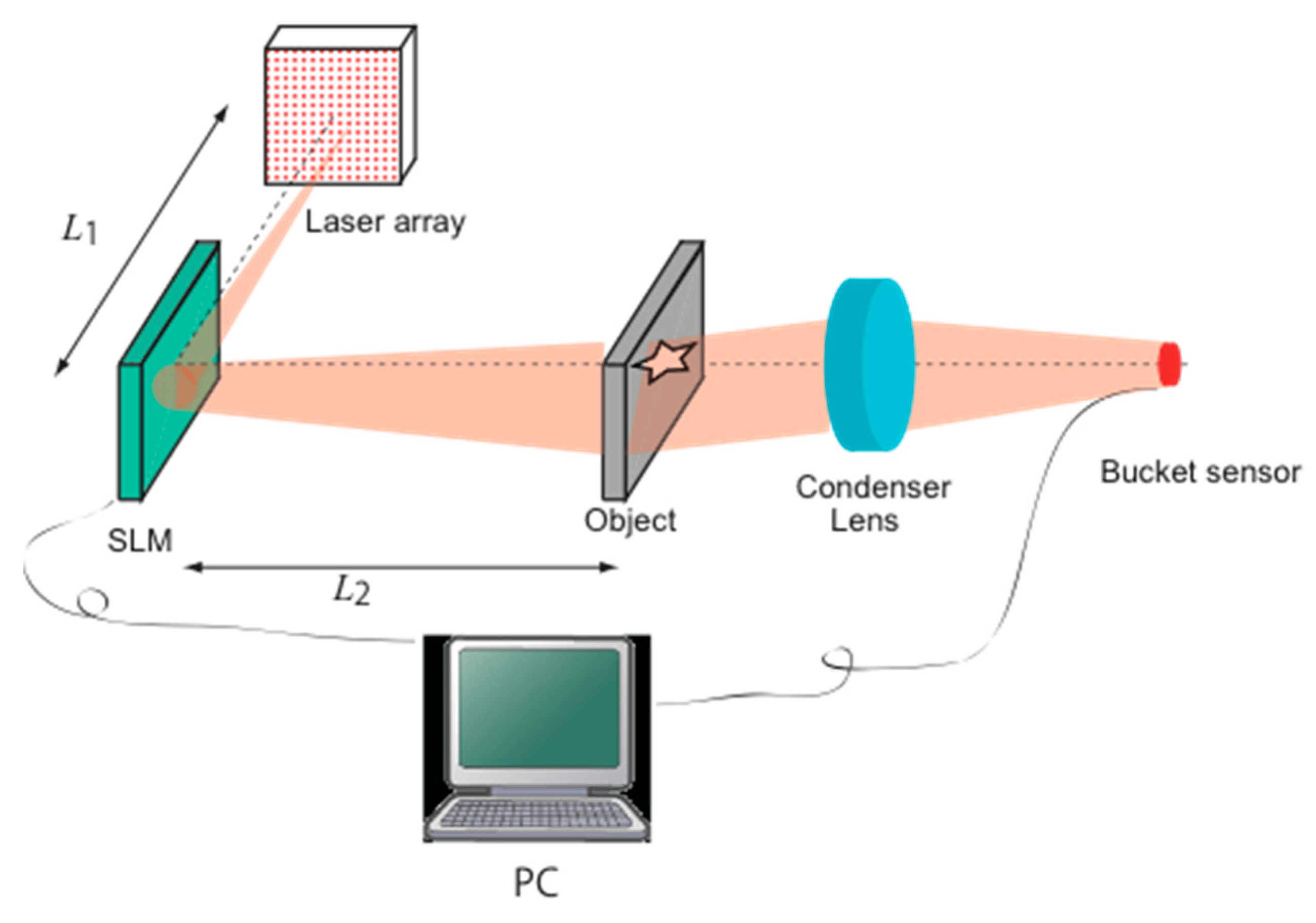
Figure 1 shows the optical layout of the proposed system. The system consists of an array of laser diodes, an SLM for random phase modulation, a convex lens, and a photo-detector. For the laser array, we will consider vertical-cavity surface-emitting lasers (VCSELs). Note that all elemental emitters have same characteristics such as spectrum, output power, and so on. First, such arrays are suitable for integration on silicon substrates. Second, with VCSELs, it is easy to implement a two-dimensional array of emitters. Finally, VCSELs can be switched on a scale of several GHz; this broad bandwidth is an important feature of the proposed method. In the optical system, each element on the laser array is emitted one by one per a measurement.
The procedure of the measurement in the proposed method is as follows. First, one source emits light; then, the speckle patterns generated by scattering on the SLM illuminate the target object. Here, the intensity distributions of the speckle patterns are defined as I1(x, y). The optical signals transmitted through the target are collected at the photo-detector by the condenser lens, with the intensity of the detected signal defined as B1. By iteratively changing the emitting position in the laser array, a set of measured data Bi (i = 1, 2, ..., n) is obtained.
According to [
13,
14], the intensity transmittance of the target
T(
x,
y) is obtained as follows:
Ii(
x,
y) is derived by numerical preprocessing as in the conventional method. In Equation (1), <
B> indicates the average of
Bi expressed as
Equation (1) is based on the second order statistical properties of the speckle intensity. This equation is derived from the intensity autocorrelation function, with the details of the derivation described in Ref. [
4].
CGI generally requires more than thousands of measurements for image reconstruction. In conventional CGI, the illumination speckle patterns are changed by refreshing the random phase modulation on the SLM. A liquid crystal on silicon (LCOS) device is often used for the SLM. The refresh rate of the device is much smaller than 1 kHz. Therefore, conventional CGI is considered to be able to work at the video rate (30 Hz). The bottleneck for the measurement speed is the rate of changing the illumination patterns.
In contrast, in our proposed method, the random phase patterns on the SLM are unchanged during the measurement. The speckle patterns in the target plane depend on the distributions of the optical signals on the SLM. These distributions are determined by the emitting position in the VCSEL array. Therefore, a set of speckle patterns can be obtained by controlling the laser array. The broad bandwidth of the VCSELs should allow a dramatic reduction in the CGI measurement time. Let us consider imaging with the proposed CGI in 30 frame per second. Also, it is assumed that a reconstructed image is obtained by 10,000 times measurements. In this case, each emitter on the laser array should be operated in 300 kHz. Also, our method can employ a random diffuser as alternative to the SLM. In this case, a set of speckle intensity distributions Ii(x, y) should be acquired in premeasurement. Although this implementation is not CGI, it is considered to be useful for simple setup and improvement of robustness for GI.
3. Numerical Verification
First, the proposed method is verified numerically. The scalar diffraction theory [
20] is used for the numerical analysis.
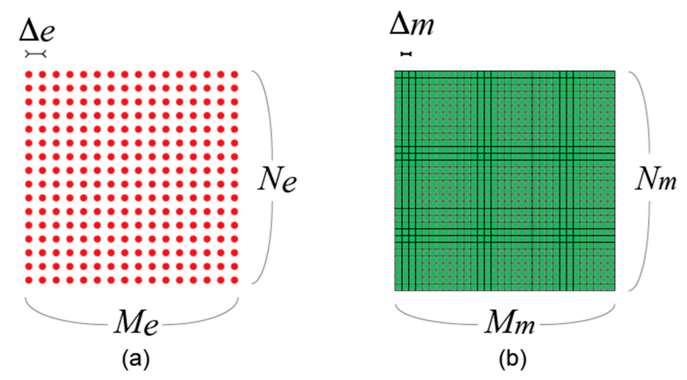
Figure 2 shows a diagram explaining the simulation models for the laser array and the SLM, respectively. First, it is assumed that a Gaussian beam is emitted by each light source, with the 1/
e2 full width of the beam defined as ∆
b. Then, the optical fields arriving at the SLM plane from the light source are derived according to the Gaussian beam propagation [
21]. After the phase modulation in the SLM plane, the optical signals are scattered and propagated to the target plane. To simulate this propagation of the scattered signals, we use the wave field tool [
22]. This tool is based on the scalar diffraction theory with angular spectrum [
21]. In the analysis, the intensity distributions are denoted by
Ii(
x,
y).
Bi is calculated as follows
Finally, a reconstructed image is obtained using Equation (1). The simulation parameters are as follows. In the laser array, the number of lasers and the pitch are defined as
Me ×
Ne and ∆
e, respectively. The number of pixels and the pixel pitch of the SLM are
Mm ×
Nm and ∆
m. The distance between the laser array and the SLM and that between the SLM and the target plane are also important parameters. The former and the latter are defined as
L1 and
L2, respectively. The values of the parameters used in the analysis are summarized in
Table 1. Also, beam profiles of each element on the VCSEL array is assumed to be gaussian for with the beam waist of 8 μm.
Figure 3c depicts the result obtained by the proposed method.
L1 and
L2 are set to 40 mm and 2000 mm, respectively. The structure of the target roughly appears in the reconstructed image, which shown that the modulation of the laser array is useful for the speckle pattern generation in CGI. However, the image is blurred. Then, when
L2 is modified to 400 mm, the averaged speckle size of
Ii(
x,
y) becomes smaller. The reconstructed image obtained with this modification is shown in
Figure 3d. In comparison to
Figure 3c, the resolution of the reconstructed image is improved by this parameter modification. The reconstructed images in
Figure 3b,d are similar. This is because the values of
L1 and
L2 are set such that the average speckle size of the illumination is the same as in
Figure 3b.
The shorter
L2, the higher is the resolution of the image. On the other hand, the longer
L2, the better is the contrast of the reconstructed images. These characteristics are discussed from the theoretical perspective in Ref. [
23], including the relation between the contrast and the speckle size. Accordingly, the contrast is improved for larger speckle size. From Ref. [
24], the speckle size
δ is given by the following equation:
In Equation (4),
D indicates the diameter of the optical distributions on the SLM. Note that
D depends on the distance from the laser array to the SLM (
L1) and ∆
b. In the verification, both parameters are constant values. Therefore, the speckle size of
Ii(
x,
y) depends only on
L2. As well known, the speckle size of the illumination patterns affects the resolution of the image reconstruction in CGI. From the reconstructed images shown in
Figure 3c,d, it can be seen that the characteristics of the obtained results are consistent with the theoretical analysis.
4. Experimental Verification
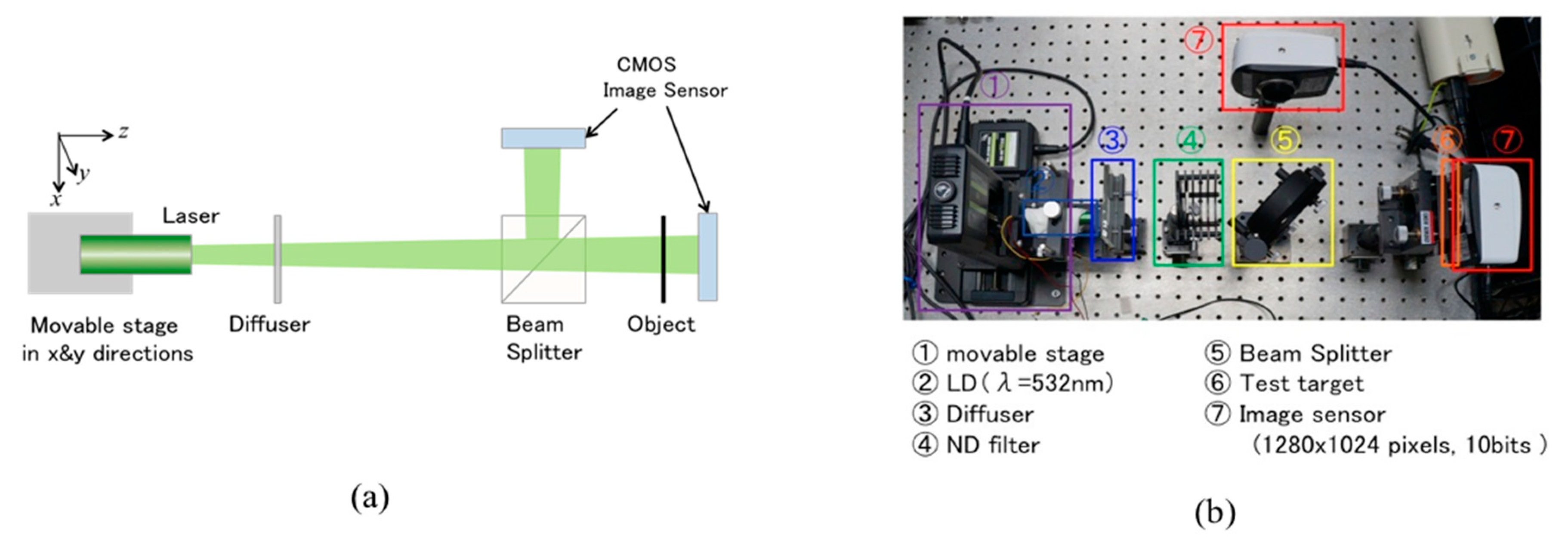
Next, the proposed method for generating speckle generation and change of patterns is verified experimentally. To this end, an optical setup is assembled.
Figure 4 shows a schematic and a picture of the experimental setup. A laser diode mounted on movable stages is utilized as an alternative for the laser array. The stages can control the position of the diode in both horizontal and vertical directions. Moreover, instead of a single photo-detector, an image sensor is used to measure the object signals in order to avoid signal loss caused by alignment errors associated with the correction optics.
Bi is derived from the sum of all pixel values. In the mathematical model of thermal ghost imaging, measured intensity on the photo detector is defined as the spatial integrals of optical intensity through the object. That means optical signals through the object in CGI can be approximated to incoherent signal. This is because coherence of speckle illumination patterns is weak due to optical scattering. Therefore,
Bi obtained by the above process can be considered to be the same as that by the photo detector.
The geometry of this setup is different from that of CGI to avoid the influence of the SLM misalignment. However, it is useful for verification of the effects of laser array modulation in CGI. A ground glass is introduced for random phase modulation. The intensity distributions of the speckle patterns are measured with a beam splitter and an image sensor. The pixel intensities obtained by the image sensor are denoted as Ii(x, y). The wavelength of the laser is 532 nm, and the pitch of the laser emission (∆b) is set to 800 μm. The values of (Me, Ne) are set to (30, 30). Thus, the total number of measurements is 900.
Figure 5 shows the results of the experiment.
Figure 5a is a picture of the target, and
Figure 5b is the result obtained by image reconstruction. From
Figure 5b, it can be seen that the symbol “5” is successfully reconstructed in the image. The reconstructed image is tilted and shifted with respected to the target. This is because the speckle distributions illuminating the target do not completely match the reference patterns. With more accurate alignment, the images are reconstructed correctly. Also signal processing based on differential ghost imaging [
6] and normalized ghost imaging [
7] are useful for not only the conventional GI but also the proposed method.
In this experiment, the target symbol is selected from the USAF 1951 chart. Attempts to measure large parts of the chart did not yield successful reconstruction because the transparent area of the chart was too wide. In Ref. [
7], it is shown that signal to noise ratio (SNR) of reconstructed images depends on transparent area in the target. The wider the transparent area is, the lower SNR is. The reason is analyzed in the Ref. [
7]. In Ref. [
25], also, the relation between the transparent area and quality of the reconstructed images is studied, and visibility is defined for assessing the reconstructed images. According to Ref. [
25], a huge number of measurements are required to improve the visibility. The proposed method is suitable for high speed measurements. Therefore, our method is considered to be useful for improvement of visibility. In Ref. [
26], a VCSEL array with 1200 emitters was used for confocal interferometry. Such an array device can be employed in the proposed method.
From the experimental verifications, it is shown that the proposed scheme for renewal of speckle illumination patterns by means of laser array modulation is useful for CGI. We have not yet completely constructed a CGI system based on the proposed scheme. For the construction, we should tackle the following next issues. At first, a VCSEL array device is assembled in the optical system. This device required to operate each emitting element with more than hundreds kHz. Next is implementation on operations for synchronization of the laser array and the photodetector. The last one is the development of high-speed signal processing to derive illumination patterns and the reconstructed image. By accomplishing these issues, fast CGI based on the proposed scheme can be completely demonstrated.
5. Discussion
With a high-speed galvanometer, a few thousand patterns of speckle illumination can be generated per second. In a situation that does not require high-quality imaging, the measured system with scanning may be useful. As another implementation for acceleration of CGI, use of DMD is mentioned. DMD can change random modulation patterns in about 30 kHz and more. In case that the target is in sparseness, DMD is effective as a device for change of speckle pattern. On the other hand, for image reconstruction of more complex structures, huger times measurements are required in CGI. In this situation, renewal operations for change of speckle should be faster. Rates of laser switching and photo detector reach more than several hundred MHz. Therefore, the proposed method is considered to be useful for wider applications.
We now discuss the features of the proposed method. One of them is updating the illumination patterns with phase modulation rather than amplitude modulation. Generally, speckle generation relies on random phase modulation and mutual interference caused by propagation. In conventional CGI, random phase patterns are changed dynamically to update the speckle patterns. In the proposed method, on the other hand, the random phase distribution is controlled by the emission patterns of the laser array. That means that the refreshing of the illumination patterns is executed through amplitude modulation. The use of amplitude modulation in CGI is quite novel. In terms of device technology, laser modulation seems to be suitable for reducing the measurement time in comparison with liquid crystal based spatial light modulators.
6. Conclusions
In summary, we proposed a method for optical measurement in CGI. In the method, laser array modulation is employed to refresh speckle patterns. The method allows reducing the measurement time of CGI. We verified the method with simulations based on the scalar diffraction theory. The numerical analysis demonstrates that the proposed method can provide a desired reconstructed image. Further, we described experimental results to verify the fundamental operations. Although the experimental setup is not a complete implementation, the usefulness of the proposed method can be seen from the obtained images.
For future work, prototyping of the experimental system can be mentioned. Moreover, we should demonstrate accelerated imaging with the prototype system. Finally, increasing the speed of the associated signal processing is also important.


