Article

Classification of Factors Affecting the Performance of Fully Grouted Rock Bolts with Empirical Classification Systems

1
Department of Civil and Environmental Engineering, Hanyang University, ERICA Campus, Sangnok–gu, Ansan 15588, Korea
2
Department of Mining Engineering, Baluchistan University of Information Technology Engineering and Management Sciences (BUITEMS), Quetta 87300, Pakistan
3
Department of Geological Engineering, Baluchistan University of Information Technology Engineering and Management Sciences (BUITEMS), Quetta 87300, Pakistan
4
Structural and Seismic Technology Group, KEPCO Research Institute, 105 Munji-Ro, Yuseong-Gu, Daejeon 34056, Korea
5
Department of Urban Infrastructure Research, Seoul Institute of Technology, 8F 37 Maebongsan-ro, Mapo-gu, Seoul 03909, Korea
*
Author to whom correspondence should be addressed.
Appl. Sci. 2019, 9(22), 4781; https://doi.org/10.3390/app9224781
Submission received: 10 September 2019 / Revised: 18 October 2019 / Accepted: 5 November 2019 / Published: 8 November 2019
(This article belongs to the Section Civil Engineering)

Abstract

:
Empirical classification systems do not provide details of the factors that affect the performance of fully grouted rock bolts, as they are based on average values. Fully grouted rock-bolt patterns during tunnel-support design are a part of the composite support, and they are functions of rock-mass quality and tunnel span. Various fully grouted rock bolts are used in situ in different environments, along with other tunnel-support materials in static and dynamic environments during tunnel construction. The rock-bolt performances are evaluated through pull-out tests that follow ASTM standards. Several field pull-out tests were conducted on cement and resin grouted rock bolts. Under groundwater flow conditions, inflated steel tube rock bolts were tested and the results were compared with fully grouted rock bolts. Based on field experiments and previous studies, the factors that affect rock bolt performances are divided into five groups with respective sub-factors. Natural parameters cannot be controlled to ensure safety, economy, and stability in tunnels. The controllable factors, too, can be varied only within a practical range. In conclusion, the factors investigated here should be considered with the empirical support pattern of rock-mass classification systems for safe and economical design.

1. Introduction

After rock-load factor classifications came into being, many empirical systems were developed for tunnel-related design. Rock-mass rating (RMR) system [1,2], rock-quality index (Q) system [3,4,5], and rock-mass index (RMi) [6,7] are internationally accepted empirical systems for rock engineering. In tunneling, rock-mass classification systems classify the rock masses to aid tunnel design. In tunnel designs, the rock-mass quality as per the classification system, along with tunnel cross-sectional sizes, are used in the preliminary support design for safe and economic construction. Economy, simplicity, reliability, and the ability to withstand the tests of time are the factors behind the acceptance of using these empirical systems in tunnel design and construction. Fiber-reinforced shotcrete and rock-bolt support are the dominant preliminary support and reinforcement systems used in rock-tunnel construction [8,9].
In the RMR system, the rock-bolt design pattern was proposed for 20 mm fully grouted bolts and for tunnels with a span of 10 m [2]. After four decades of experience using the RMR system in tunneling, the rock-bolt length and spacing were extended for rock support as functions of tunnel span and rock-mass quality [10]. In Q systems, the 20 mm diameter rock-bolt spacing is a function of rock-mass quality, along with the presence of shotcrete (either sprayed or otherwise), and their length depends upon the tunnel span [11]. In RMi systems, rock-bolt spacing is a function of the ground quality and tunnel size, along with the presence of shotcrete (either sprayed or not), and the length of the rock bolt depends upon the tunnel span and block size [7].
The main objective of rock reinforcement is to make greater use of the inherent rock-mass strength and the rocks’ deformation characteristics to enable self-supporting rock media, and rock bolts are used for this purpose. This rock-mass reinforcement system comprises four principal components, which include the rock mass, reinforcing element, internal fixture, and external fixture [12]. The rock-mass classification system proposes a 20 mm diameter rock bolt length and spacing for a tunnel cross-section based on the rock-mass quality, although several factors have been studied in the past few decades to investigate the performance of rock bolts in different underground excavations.
In this study, field tests were conducted as per ASTM (American Society for Testing and Materials) standards, to investigate the performance of fully grouted rock bolts under different rock-mass conditions defined by empirical classification systems. This study is the continuation and extension of our previous research, in which fully grouted rock bolts were used for the calculation of rock-mass quality for the extension of empirical classification systems [9,13,14]. Along with the field tests conducted for this work, much literature related to the fully grouted rock-bolts tests conducted either in a laboratory or on the field was also generated. Based on field tests and the literature, the different factors that affect the performance of bolts in different conditions are broadly categorized into five groups: bolt, fixture, rock mass, stress, and installation-related factors. Each group has several parameters that affect the performance of the rock bolts. Experimental results from the field and literature are combined, mainly focusing on the fully grouted rock bolts and an attempt is made to determine the interdependency of parameters aiming to design the efficient and economic rock-bolt patterns by using empirical classification systems.

2. Materials and Methods

2.1. Rock-Mass Classification System and Rock-Bolt Design

In each empirical rock-mass classification system, the classification criterion is unique, owing to the rock-mass characterization, followed by the classification, and the rock-mass quality is obtained in the numerical, as well as descriptive, form. The value obtained from each empirical system is used, along with the tunnel span, for support-design decisions, and, further, these systems relate each rock-mass class to a specific engineering problem in tunneling.
The range of the RMR system is from 0 to 100, dividing the rock mass into five quality classes (very good, good, fair, poor, and very poor), with 20 points each. In the RMR system, rock-bolt design (20 mm diameter, fully grouted) is based on the tabulated guidelines for 10 m wide horseshoe-shaped tunnels, where the bolt length and spacing are the functions of rock-mass quality [2]. After the successful utilization of RMR for decades, the rock-bolt design rules were modified for any size of tunnel, taking the rock-bolt pattern (length and spacing) as a function of the tunnel size and rock-mass quality. According to the modification, rock-bolt length (Lb) is a function of the rock-mass quality and tunnel span, and it can be calculated by using Equation (1). The rock-bolt spacing (Sb) depends upon the rock-mass quality and can be calculated with Equation (2) [10]. For RMR values higher than 85 points, the system suggests spot bolting.
s p a n   ( m ) = ( L b ( m ) + 2.5 ) R M R 89 + 25 52 3.6
S b   ( m ) = 0.5 + 2.5 R M R 89 20 65   ( 20 < RMR 89 85 ) S b   ( m ) = 0.25 + ( R M R 89 10 ) 1.5 140   ( 10 <   RMR 89 20 ) S b   ( m ) = 0.25   ( RMR 89 10 )
In Q-system classifications, the rock mass is divided into nine classes (exceptionally good, extremely good, very good, good, fair, poor, very poor, extremely poor, and exceptionally poor), based on the rock-mass quality values obtained from Equation (3) or (4) [3,5].
Q = ( R Q D J n ) × ( J r J a ) × ( J w S R F )
Q c = ( R Q D J n ) × ( J r J a ) × ( J w S R F ) × ( σ c 100 )
where RQD (rock quality designation) has a minimum score of 10, Jn symbolizes the score of the joint set number, Jr is the score for the roughness of the joint surface, Ja symbolizes the score for the clay filling or degree of alteration, Jw symbolizes the groundwater pressure effect scores, and the stress reduction factor (SRF) is the score for faulting, strength, and stress ratios in hard rocks, and squeezing or swelling. In Equation (4), σc is the uniaxial compressive strength of intact rock.
The rock-mass quality value is combined with the equivalent dimension (De), to obtain the necessary support for the tunnel. De is based on the safety requirement and tunnel span and can be calculated with Equation (5). The safety requirements depend upon the use of the tunnel. For safety requirements, the excavation support ratio (ESR) was introduced.
D e = S p a n   ( m ) E S R
ESR values are suggested for different tunnel categories based on their use; however, this can be used in each country, as per their safety standards for the tunnel [15,16]. The length of the rock bolt depends upon the tunnel span (B), as calculated with Equation (6) [3]:
L b ( m ) = 2 + 0.15 B E S R
The rock-bolt spacing can be found from the Q-system support chart that is a function of the rock-mass quality and presence of fiber-reinforced shotcrete (either sprayed or otherwise) for a 20 mm diameter fully grouted rock bolt [5,11].
The RMi system was proposed by Arild Palmstrom, based on the reduced rock strength caused by jointing, and it divides rock masses into five classes (very high, high, medium, low, and very low) [6,7]. In the RMi system, the ground behavior reflects the estimation of the tunnel support. The ground behavior is divided into continuous and discontinuous classes, based on the continuity factor (CF), which is the ratio of tunnel diameter (Dt) to block diameter (Db). Owing to the limitation of cases for the continuous ground, more details are available in the chart and equation for the discontinuous ground (5 < CF < 100). In the discontinuous ground, ground condition (Gc) is combined with the size ratio (Sr) to obtain the required support for the tunnel. Gc and Sr can be defined by using Equations (7) and (8), respectively [7].
G c = R M i × S L × C
S r = C F × C 0 N j = ( D t D b ) × ( C 0 N j )
where SL = stress level adjustment; C = gravity adjustment factor for support in the roof or in the wall; C0 = adjustment for joint orientation; Nj = adjustment for number of joint sets.
Equations (9) and (10) are suggested for Lb calculation from Db and Dt and tunnel-wall height (Wt) [7].
L b ( r o o f ) ( m ) = 1.4 + 0.16 × D t ( m ) × ( 1 + 0.1 D b ( m ) )
L b ( w a l l ) ( m ) = 1.4 + 0.08 × ( D t ( m ) + 0.5 × W t ( m ) ) × ( 1 + 0.1 D b ( m ) )
Rock-bolt spacing is a function of Gc (37.6%) and Sr (62.4%) in the shotcrete area.

2.2. Field Test Details

The pull-out test scheme of rock bolts was conducted at the construction site for the Suseo-Pyeongtaek high-speed railway in the South Korean capital, Seoul. This site features the weathered gneiss rock, soft gneiss rock, and moderate gneiss rock assessed on three rock-mass classification systems (RQD, RMR, and Q systems), as shown in Table 1. Owing to the stress–strain relationship at the tunnel face [17], the rock-mass quality at the tunnel face during construction was comparatively lower than that predicted during the design. At the tunnel face, soft filling materials were observed in the dense joints. The groundwater leakage rate was 0~3.78 L/min from the soft rock and weathered rock, as shown in Figure 1a. The tunnel in this construction site was 12.6 m wide and 9.7 m high, with an average depth of 50 m at the location where pull-out tests were conducted. The conventional method was used during tunnel construction and was supported with fiber-reinforced shotcrete and rock bolts (25 mm in diameter). The thickness of shotcrete is 200, 150, and 100 mm for weathered, soft, and moderate rock mass, respectively. The 4 m long rock bolts were used in the moderate and soft rock masses, and the 5 m long rock bolts were used in the weathered rock mass.
Pull-out tests were conducted to examine the behavior of rock bolts under ASTM standards [18] for 3, 4, and 5 m rock bolts in the three different rock-mass classes of Table 1. The tests were executed on fully grouted rock bolts, D25, installed in a 38 mm diameter drilled hole and with a water–cement ratio of up to 40%. Instead of the water–cement grout, resin is used as grout material in a few tests, as well. The influence of the mortar’s curing time on the rock-bolt pull-out behavior was studied for the weathered and moderate rock mass. For the purpose of comparison, the inflated steel-tube rock bolts were also tested via the pull-out test methods in the wet ground condition. The details of 142 field tests, whose results are included in this manuscript, are shown in Table 2. During the expansion and installation of this type of rock bolt, the water pressure was increased up to 30 MPa. During the tests, the pull-out force was incremented by 10 kN per minute, and the load displacement was measured at each step. The pull-out failure was defined when either the total displacement reached 12.7 mm or the maximum load remained constant with displacement. Based on dry and wet conditions, the wet condition is further divided into small and large inflow sections, taking 1.0 L per minute as a reference. Figure 1b, c shows the machine and the parts used during the test, and the points of the pull-out test, respectively. The main components of the rock-bolt pull-out test machine are the hand pump with a dial gauge, flexible hose pipe, and face plate for the measurement of the working and ultimate capacities of the rock bolt. This manually operated piece of equipment has a pull-out capacity of 300 kN and was operated adequately during the field tests, following ASTM standards. Different points were selected due to the ground grade/type, water inflow, and length of the rock bolt installed, as per the construction design of the project.
Data from previous studies regarding the factors affecting the performance of fully grouted rock bolts (conducted either in the field, laboratory, or through modeling) are combined. Based on the experimental results from the field and previous studies, all the factors that affect the performance of fully grouted rock bolts are presented.

3. Results

3.1. Factors Affecting the Performance of Fully Grouted Rock Bolts

Rock-bolting is one of the two techniques (reinforcement and support) for excavation stabilization and is the output of empirical systems during the preliminary support design of tunnels. Comprising four components (rock-mass, bolt, internal, and external fixtures), rock bolts can be classified into the following three types, based on the load transfer between the rock mass and bolt [12]:
  • Continuously mechanically coupled (CMC);
  • Continuously frictionally coupled (CFC);
  • Discretely mechanically or frictionally coupled (DMFC).
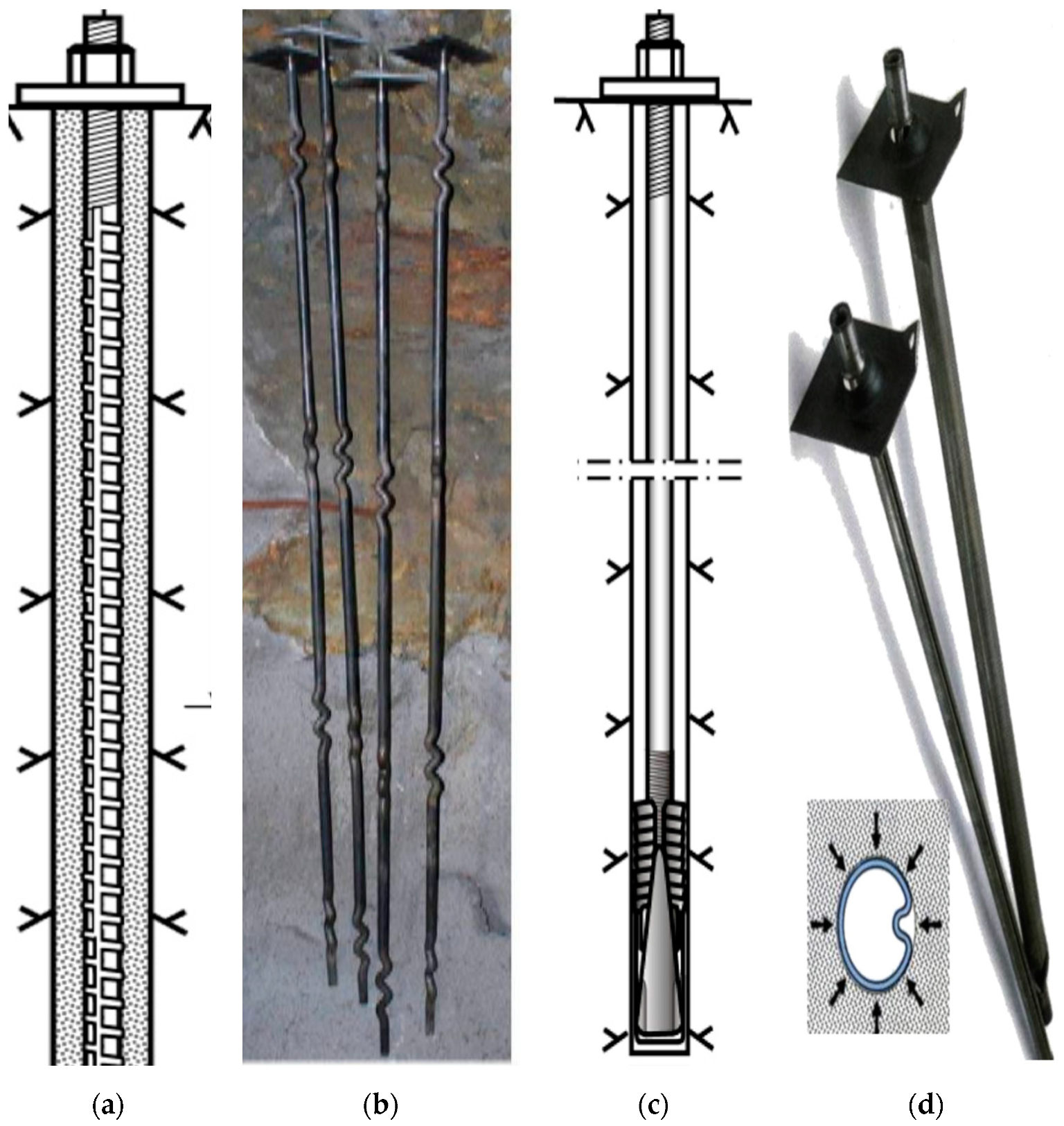
Fully grouted (cement or resin) rock bolts belong to CMC systems, inflated steel-tube rock bolts are CFC systems, and expansion shell bolts belong to the DMFC category. The first type is comparatively simple in installation, versatile, effective in reinforcement, and also economical. This type is widely used in underground excavation projects for stability [19,20,21], and, owing to this reason, empirical systems also focus on fully grouted rock bolts. The CMC bolts are strong and stiff bolts compared to the last two types, which are flexible and absorb large ground deformation. However, after the development of D-bolts (also fully grouted), the D-bolt is preferred over the expansion shell, inflated steel-tube rock bolt, and split-set type, owing to its high strength and large deformation capacity [22]. A few types of bolts used for stability are shown in Figure 2 [23].

3.1.1. Rock-Bolt-Related Factors

Type and Shape

Fully grouted bolts are divided into two groups, i.e., rock bolts and cable bolts, which are further subdivided into smooth surface bars, ribbed bars, single conical lugged bars, double conical lugged bars, D-bolts, plain cage, bird cage, nut cage, mini cage, etc. [23,24,25], of which a few are shown in Figure 2. RMR, Q, and RMi systems focus on rock-bolt designs in tunneling because cable bolts are generally used in mining engineering applications, whereas rock bolts are used in both mining and civil engineering projects [26]. The bolt type has a strong influence on their deformation behavior [24,27,28].
Grouted rock bolts (CMC type) have the advantage of high load-bearing capacity, owing to their better load-transfer mechanisms. The load transfer in fully grouted rock bolt is due to adhesion or friction and/or mechanical interlocking. There is a small amount of adhesion between the grout–bolt interface [29], although some researchers conclude that there is no adhesion [30]. The main mechanism involved in load transfer is mechanical interlocking. Mechanical interlocking is the result of filling the irregularities between the rock bolt and drilled-hole peripheries (rock). The test results show that the bolt surface profile has a dominant influence on the load transfer capacity [24,25]. Rougher bolt profiles result in improved load transfer as compared to the plane surfaces. The magnitude of the shear stress and stiffness developed along the bolt/resin/rock interface is influenced by the bolt profile configurations, i.e., rib spacing and rib height [31]. For a rib height of 1.8 mm, experimental results show an increase of more than 25% occurs in the peak load during the rock bolt pull-out tests for 48 mm rib spacing, compared to those for the 12 mm rib spacing [32].

Effect of Rock-Bolt Length

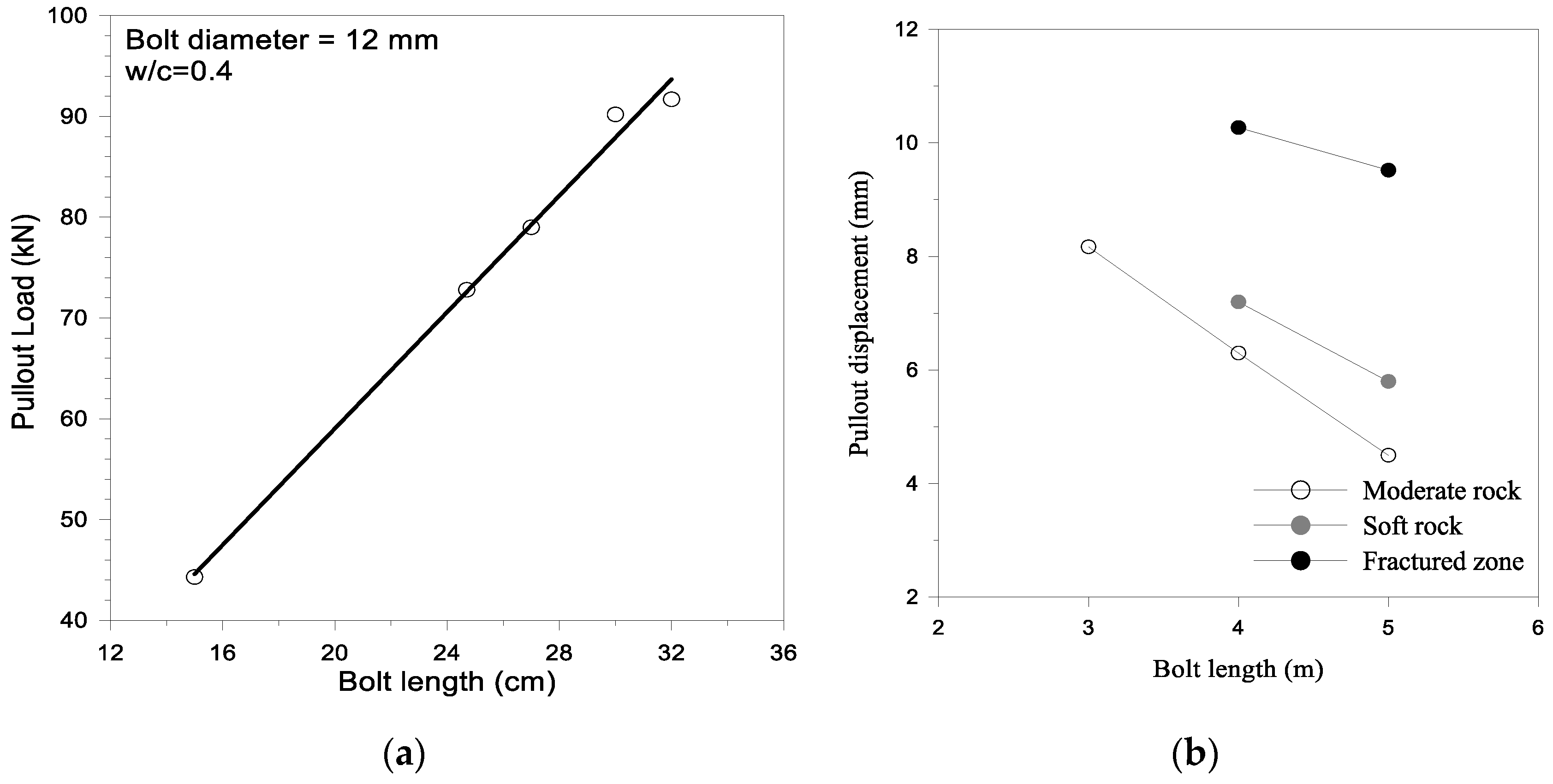
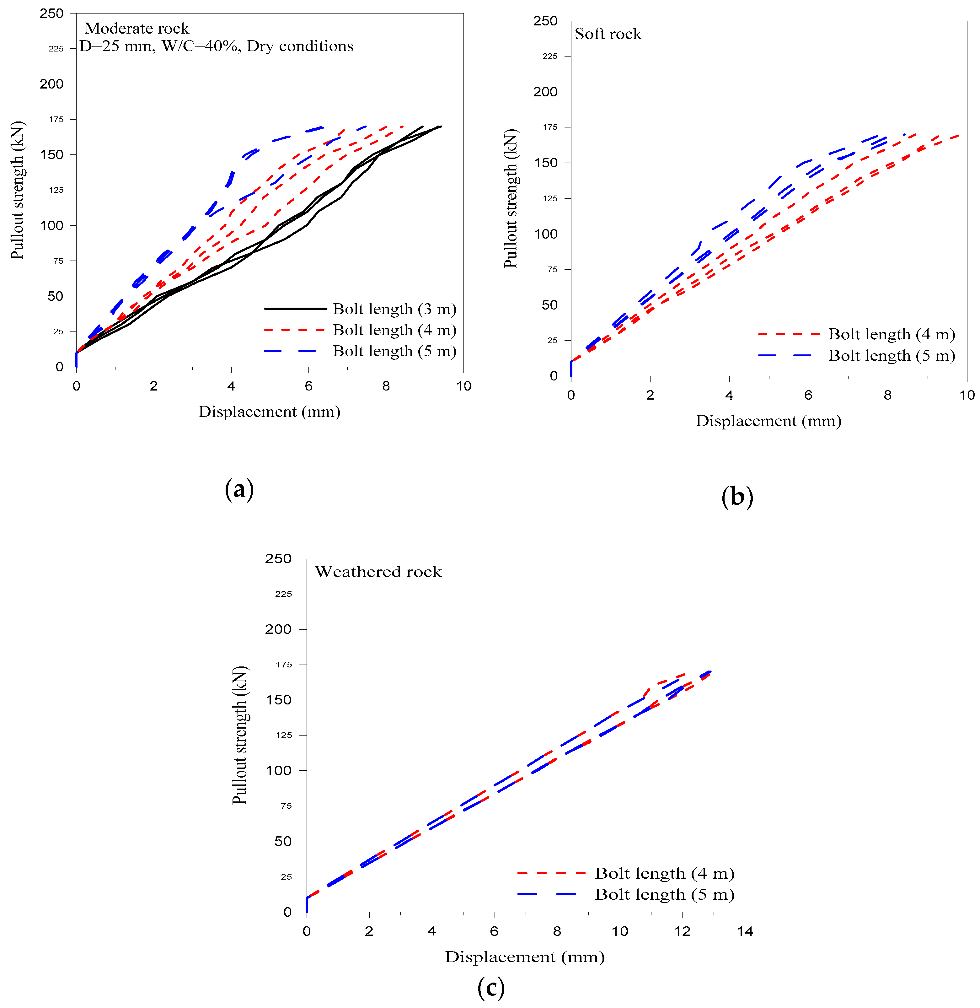
As discussed in Section 2.1, empirical classification systems propose rock-bolt lengths that depend upon the tunnel size and rock-mass quality. During rock-bolting, the load from the unstable rocks around the tunnel perimeter is transferred to stable rock through the bolt. Therefore, the length of the rock bolt should be sufficiently in excess of the thickness of the plastic zone around the tunnel, for stability [33]. Laboratory test results show that the maximum load-carrying capacity increases with the grouted length of the bolt [34,35,36], as shown in the Figure 3a. This laboratory test results are for the 12 mm diameter rock bolt grouted in the 22 mm drilled hole. The water–cement ratio is 40%, and the annulus size is 5 mm. The bolt pull-out force increases linearly with the length. The load-carrying capacity of the rock bolt should not be increased up to the ultimate tensile strength of the anchor, and the corresponding length is called the critical anchor length. The effect of rock bolt length was determined for the three rock-mass types (moderate, soft, and weathered rock) during pull-out tests for 3, 4, and 5 m long bolts. As shown in Figure 3b, the average pull-out displacement decreases with the increase in rock-bolt length. In the field test, 25 mm diameter rock bolts were tested in a 38 mm diameter drilled hole in three different rock-mass classes. The water–cement ratio was kept constant in dry rock-mass condition. The length effect is dominant for moderate rock and negligible for weathered rock (Figure 4).

Effect of Bolt and Hole Diameter

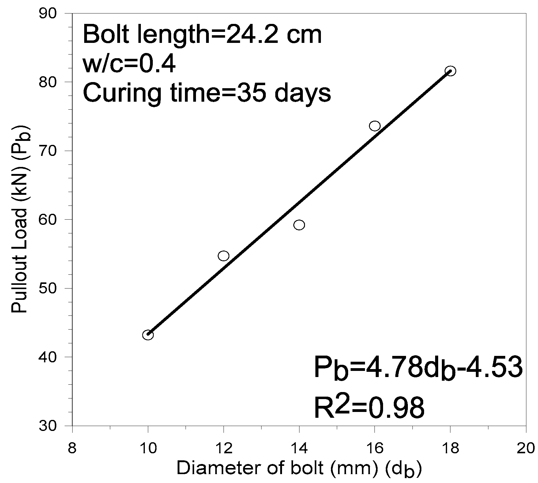
Empirical systems suggest bolt patterns based on 20 mm diameter rock bolts. Critical anchor length of the rock bolt increases with the increase in rock bolt’s diameter. In the field tests conducted for this study, 25 mm diameter rock bolts were used in 38 mm diameter drilled holes. The laboratory test conducted on different diameters of rock bolts indicates that the maximum pull-out load of the fully grouted bolts increases linearly with the cross-sectional area of the bolt, while the embedment length was constant, as shown in Figure 5 [36]. However, extremely thick bolts are uneconomical and difficult to install. The ratio of the borehole diameter to bolt diameter is a parameter in addition to the variation in the bore hole length and friction of the borehole surface that results in the slippage at the grout–rock interface [37]. The optimum difference between the diameters of the bolt and hole is not greater than 6.4 mm, giving an annulus of approximately 3.2 mm [38] for enhancing the load transfer capability. Large holes can result in poor resin mixing in the case of resin-grouted rock bolt, while smaller holes (annulus < 3 mm) can cause rock-bolt insertion problems. The annuli fluctuate from 2.5 to 6.4 mm and provide better results in strong rocks [39].

Face Plate

The performance efficiency of fully grouted rock bolt is based on the efficiency of load transfer in load-transfer mechanisms [31]. Face plate, which is the external fixity of the rock-bolt system [12], enhances load transfer to the bolt [40]. Similar to static conditions, the presence of face plates in dynamic loading enhances the load transfer where the rate of loading is high [41]. The bolt plate provides the essential surface-retaining support, and its loss will have a direct negative impression. Field observations show that, in the case of largely deformed rock masses, bolt plates are quite often heavily loaded, and bolt threads sometimes fail prematurely, as the threaded part of the bolts have 25% less bearing capacity [21]. To avoid overstressing the plate and thread, the first anchor of the D-bolt (Figure 2c) is located very close to the bolt thread. This anchor can then carry a large portion of the ground stress that would otherwise be transferred to the plate/thread, which significantly improves the loading condition of the plate/thread [22].

3.1.2. Effect of Grout Properties and Thickness

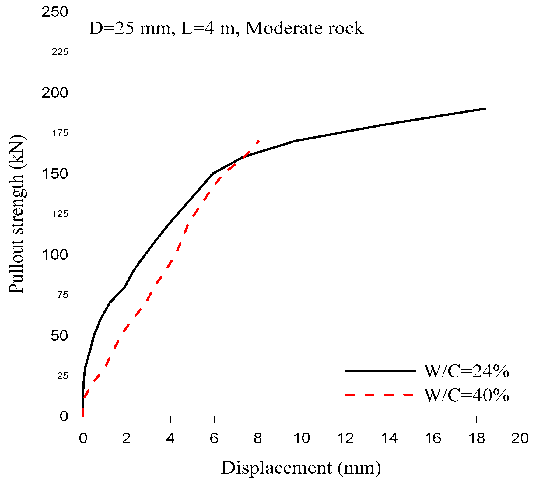
Based on the grout-material types, fully grouted bolts are divided into two sets, i.e., resin-grouted and cement-grouted bolts. The mechanical properties of resin are comparatively high [42]. The resin-grouted bolts are more rigid than the cement-grouted ones [43]; however, poor resin mixing and cartridge accumulation in bolted holes decrease their efficiency. The best resin mixing and bolt encapsulation occur in the bolt’s middle region, whereas, at the bore-hole end, the cartridge accumulation causes anchorage problems [44]. This anchorage problem, which arises due to poor mixing, increases the reinforcement cost from 10%–30% [45]. Cementitious grout types, on the other hand, are made of a mixture of cement, water, and other substances that may reduce shrinkage, increase pump-ability, or improve the mechanical properties of the mixture. Mechanical properties of the grout govern the bolt capacity, which can be changed by altering the water-to-cement ratio, additives, proper mixing of grout components, and curing time [36]. The pull-out capacity of the cement-grouted bolts increases with the decrease in the water–cement ratio, and its optimum value is 0.34–0.4 in terms of pump-ability and resistance [35,36]. The effect of the water–cement ratio was investigated in moderate rock masses for a 4 m length rock bolt, and the average test result is shown in Figure 6. For the purpose, pull-out tests were carried out on 25 mm diameter rock bolts for the water–cement ratio of 24% and 40%.
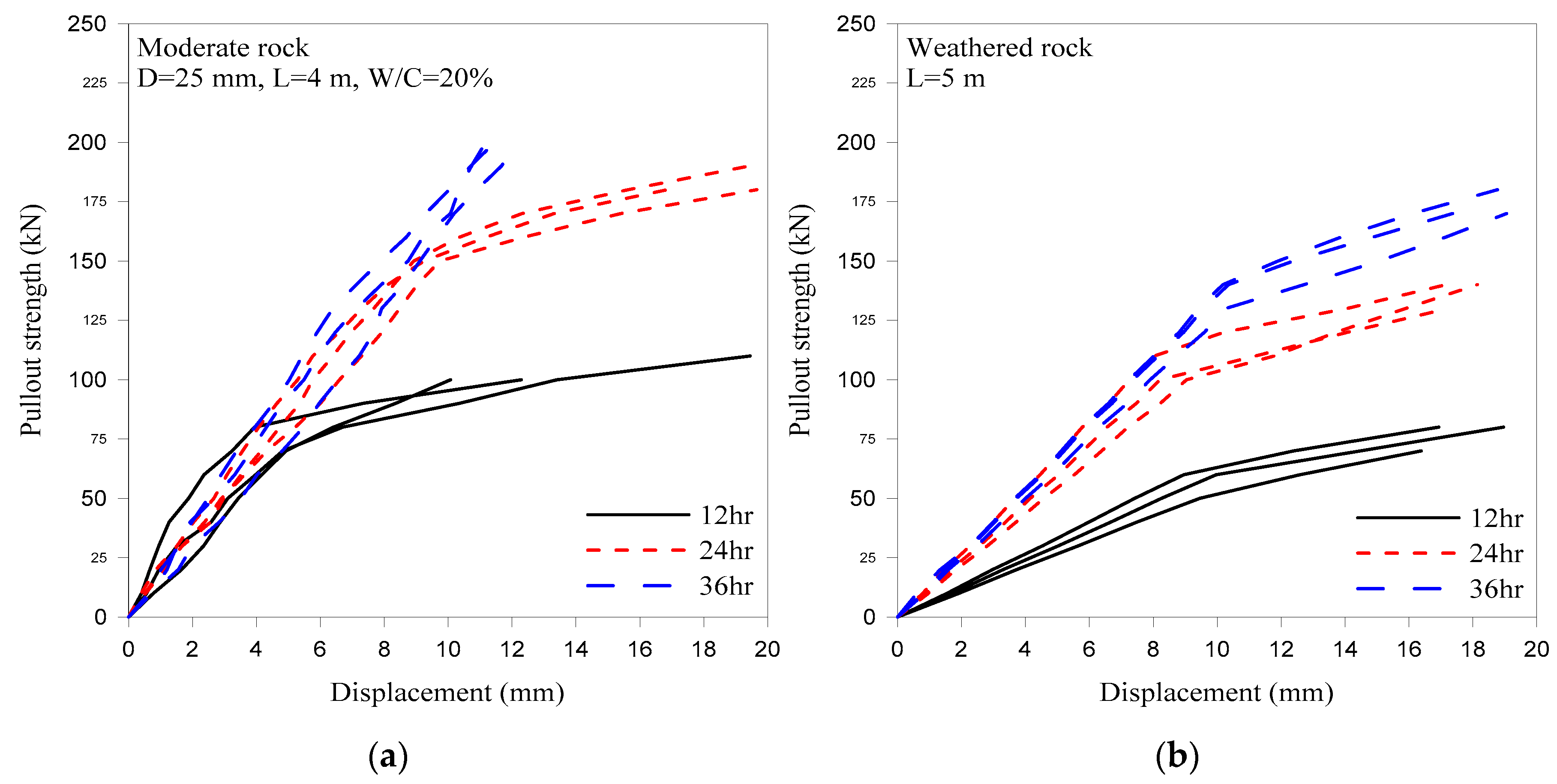
Cement-grouted rock bolts have several limitations for immediate support applications, owing to settling time requirements. The load-carrying capacity of cement-grouted rock bolt for different curing times (12, 24, and 36 h) was tested, and results are shown in Figure 7. For the same diameter and water–cement ratio, the results of 18 pull-out tests for the two rock-mass classes and three curing times are shown.

3.1.3. Effect of Stresses

In-Situ Stresses

At low depths, the in situ stress state represents a minor concern in the stability of the rock mass surrounding an underground excavation. Presently, tunnels are constructed at great depths [46,47,48] where the stresses are the main factors that determine the behavior of the tunnel. In empirical classification systems, the rock-bolt design that uses Q-system is preferable over the RMR and RMi systems, owing to the stress reduction factor for the category of “competent rock having rock-stress problem”. When the magnitude of maximum boundary stress in the vicinity of the opening (σmax) is close to the uniaxial compressive strength of the rock mass (σcm), the rock is overstressed [49]. If the rock is weak and soft, it is frequently observed that either the face plate of the bolt is highly loaded or the thread of the bolt is pulled until it fails [21]. In the case of hard rocks, the rock spalls and sheds pieces like onion skins behind the bolt plate, leaving a short section of the bolt protruding out of the rock surface [22]. In such high-stress environments, the conventional CMC does not adapt well. Energy-absorbing bolts that are characterized by their high load-carrying capacity and large deformation capacity are suitable for such a position. The newly devised energy-absorbing rock bolt called D-bolt (Figure 2c) is a fully grouted rock bolt; it is the most effective energy-absorbing bolt when compared to existing non-grouted energy-absorbing rock bolts [23].

Induced Stresses

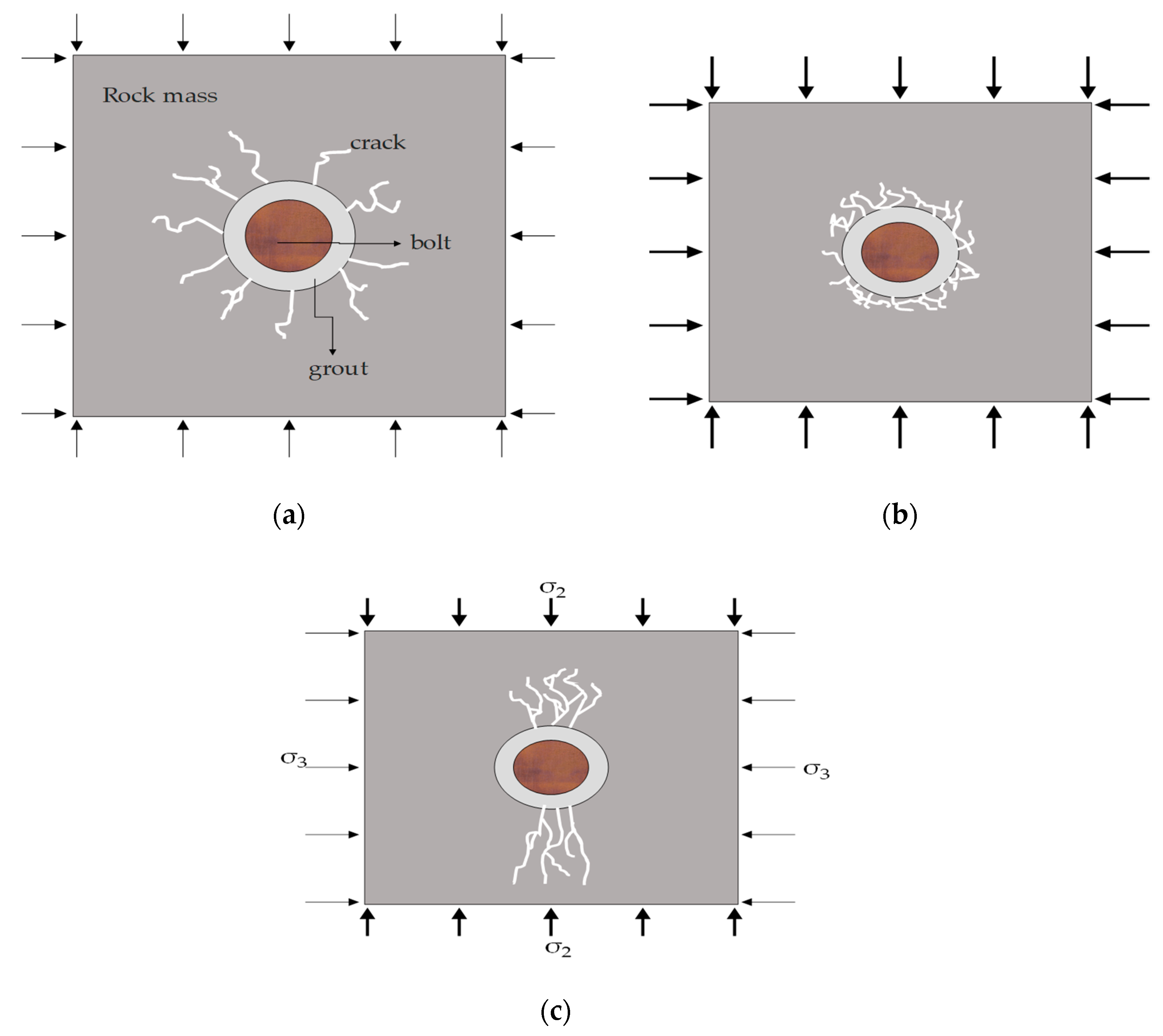
During tunnel excavation, the field stress condition is disturbed. This disturbance in the field stress is a governing factor influencing the rock-bolt capacity. A stress decrease that is perpendicular to the longitudinal axis of the bolt leads to unstable splitting of the grout, whereas an increase reduces the potential for unstable splitting. A change in stress parallel to the longitudinal axis of the bolt has an opposite effect. In high-stress environments, the consideration of the stress-change effect is important during bolt design and installation [50]. Along the tunnel periphery, the stress condition around each rock bolt is not hydrostatic. The major and minor principal stress values and directions have a direct effect on the crack propagation in the rock surrounding the bore hole during the pull-out test, as shown in Figure 8. Laboratory studies confirm that, by decreasing the confining stresses, the bolt capacity decreases and the radial fracturing increases [43].

Dynamic Loading

Empirical classification systems do not consider dynamic loading, although the conventional tunnel practices involve blast-induced vibrations in close proximity to the installed grouted rock bolts. Field test results show that no decrease was observed in the strength of rock bolts in the field pull-out test, where the bolts were installed 3.4 and 22 m away from the blasting face, irrespective of the grout’s settling time [51]. The effect of blast induced vibration from the adjacent tunnel shows that it affects the rock-bolt performance [52]. A numerical study of fully grouted rock bolts under dynamic loading showed that, if the vibration wave propagates from the opposite side, perpendicular to the rock bolt longitudinal axis, multiple wave reflections from the free surface along the excavation periphery affects the bolt performance [41].

3.1.4. Factors Associated with Installation

Time of Installation

Grouted rock bolts are stiffer than others; however, owing to their nature, they allow some deformation to activate the load-transfer mechanism and also require some time for installation. After excavation, the time of fixing bolts has an important effect on the tunnel convergence control. Extremely late installation results in considerable excavation convergence. Moreover, the bolt will probably become overstressed before equilibrium is reached [53]. This clearly shows that the stand-up time has a direct relation with the time of installation of the bolt, and for the same excavation size, the stand-up time is the function of rock-mass quality. The support system should be installed as soon as possible after the excavation in order to prevent the loss of a significant share of the inherent strength of the rock mass.

Effect of Tension

The main advantage of the tensioned bolt is that it increases the shear stiffness of the bolted joint as soon as it is installed. The fast-setting resin allows the tensioning of the bolt a few minutes after installation. It should be noted that, when the bolt is pre-tensioned, some elastic deformation of the bar/bolt is utilized, and extra deformation may be induced in the bolt when there is movement in the reinforced joint. Laboratory studies show that pre-tensioning of the bolts produce clamping effect on joint surface; this helps to reduce joint dilation, increases the inherent shear strength of the joint, and reduces the shear displacement [54].

Inclination with Joint

Rocks surrounding the tunnel have irregular joint patterns. Typically, during rock-bolt installation, the recommended rock bolts are applied perpendicular to the tunnel surface. These rock bolts, perpendicular to the surface, have a variable inclination with the joints. Laboratory investigations show that a fully grouted bolt installed at an inclination to the joint has higher stiffness and contributes more toward the shear strength of the bolted blocks as compared to a perpendicular bolt [54]. The maximum shear resistance of the bolted joints increases with the inclination of the bolt (with respect to normal to the joint surface) provided that there is significant friction in the joint; otherwise, the bolt inclination has no effect on the maximum resistance [55]. The optimum angle of bolt inclination with respect to the joint is from 30°–60° and shear displacement at failure is minimal for bolt inclination between 40°–50°.

Composite Response

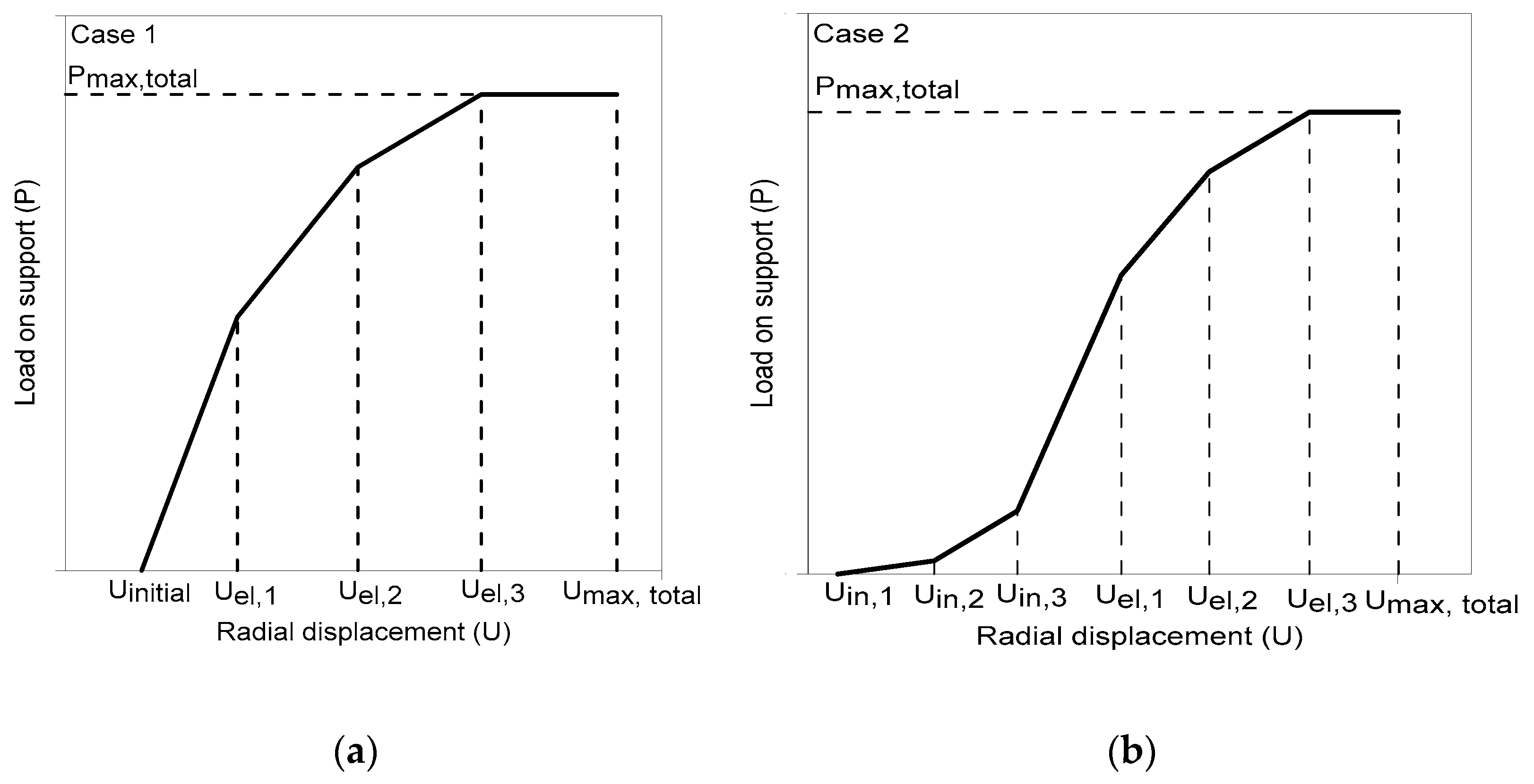
Empirical classification systems propose compound support systems. If grouted rock bolts are installed with other support systems, like shotcrete and steel sets, then the total stiffness of the support and reinforcement system in the elastic field is given by merely adding the single stiffness by Equation (11). The reaction time of the composite system depends upon the installation time of the individual support/reinforcement and distance from the excavation face (Figure 9) [56].
k t o t a l = i k i
where Ktotal = total stiffness of the composite system, and Ki = individual support/reinforcement stiffness.

3.1.5. Effect of Rock-Mass Type on the Performance of Fully Grouted Rock Bolt

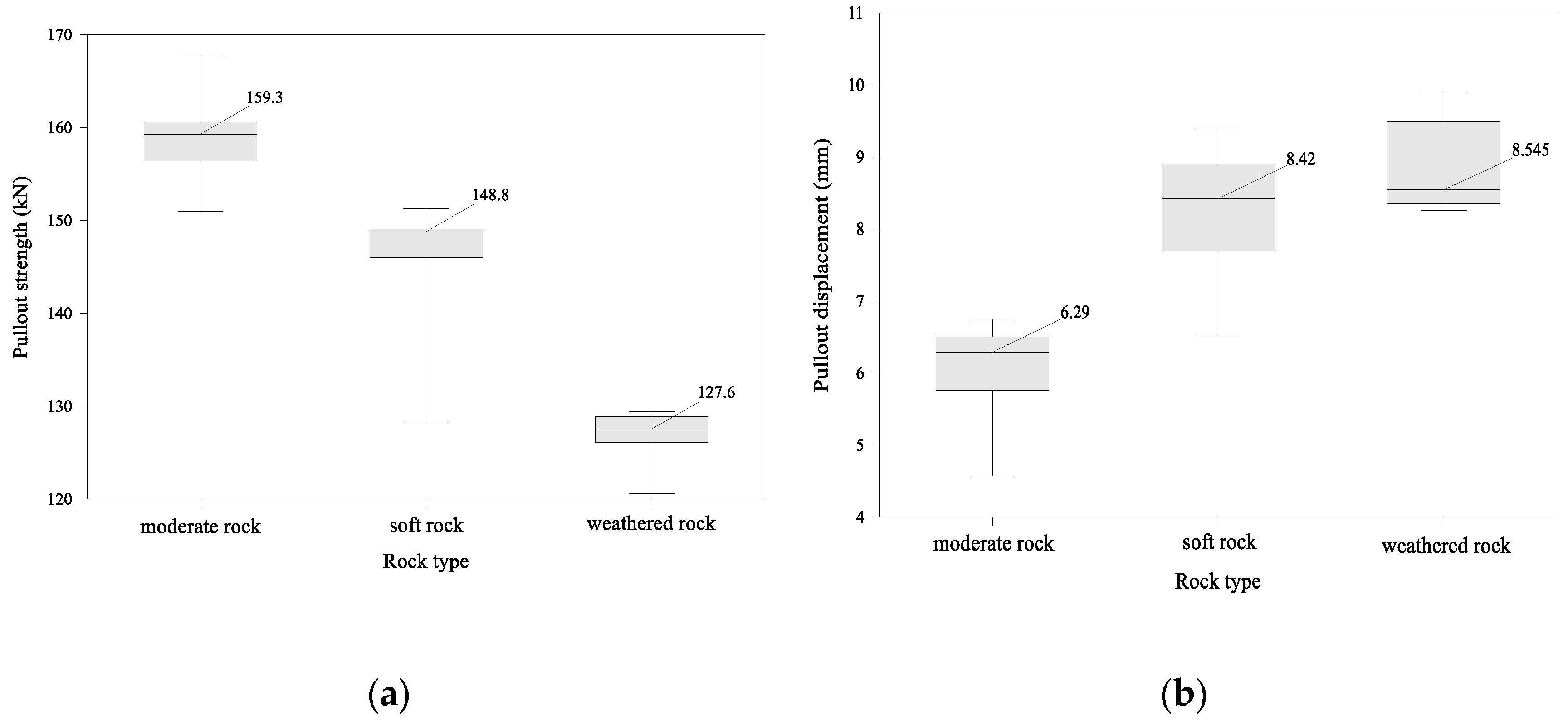
Several parameters affect the rock-mass conditions, including the strength of the intact rock, joints frequency, groundwater inflow, condition, and orientation of joints, with respect to excavation [2,5,7]. The core objective of rock reinforcement is to make greater use of inherent rock-mass strength and deformation characteristics to enable the rock media to support itself by improving the mechanical properties, provide rock confinement, and stabilization of jointed rock masses. The load that acts on the support system is referred to as the support pressure, and the support pressure depends on rock-mass quality and excavation span [5,57]. Rock-bolt performance is restricted by the effectiveness of the load-transfer mechanism. This load-transfer mechanism is determined by the anchorage performance of the rock bolt through a rock-bolt anchor-pull test [58]. Rock-mass strength, which depends on the rock-mass quality, is one of the factors that can affect the load-transfer characteristics in fully grouted rock bolts. The effect of the rock-mass type on fully grouted rock-bolt behavior was investigated by performing pull-out tests on the moderate rock, soft rock, and weathered rock. Test results in term of the median pull-out strength and displacement are shown in Figure 10. Rock-mass quality shows a direct relation with rock-bolt pull-out strength and an inverse relation with pull-out displacement.
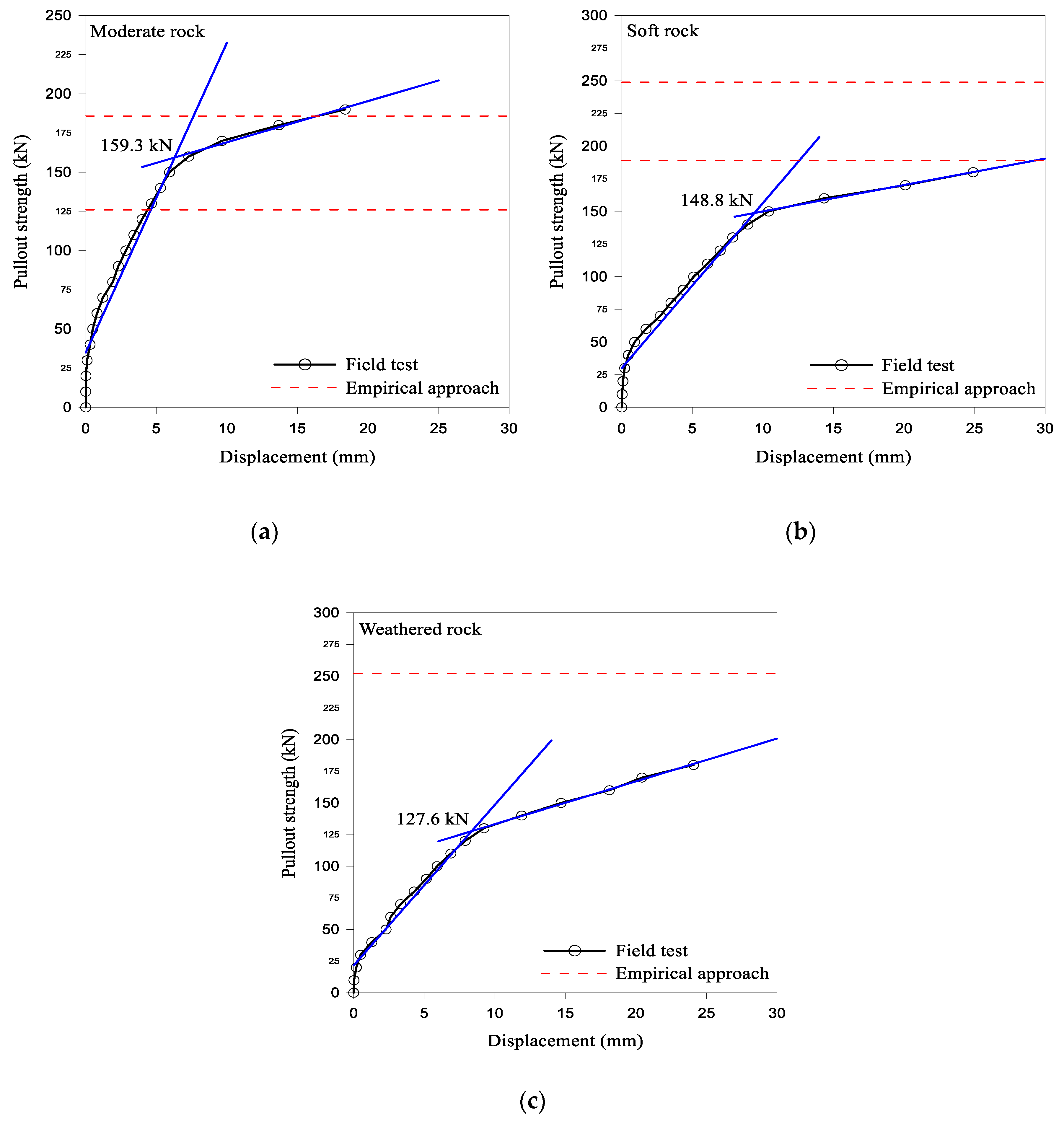
Equation (12) [2] was used for the calculation of support load, and the results were compared with the median pull-out strength results (Figure 10), as shown in Figure 11.
P = 100 R M R 89 100 × γ × B
where B = the tunnel span (m); γ = the rock density (kg/m3).
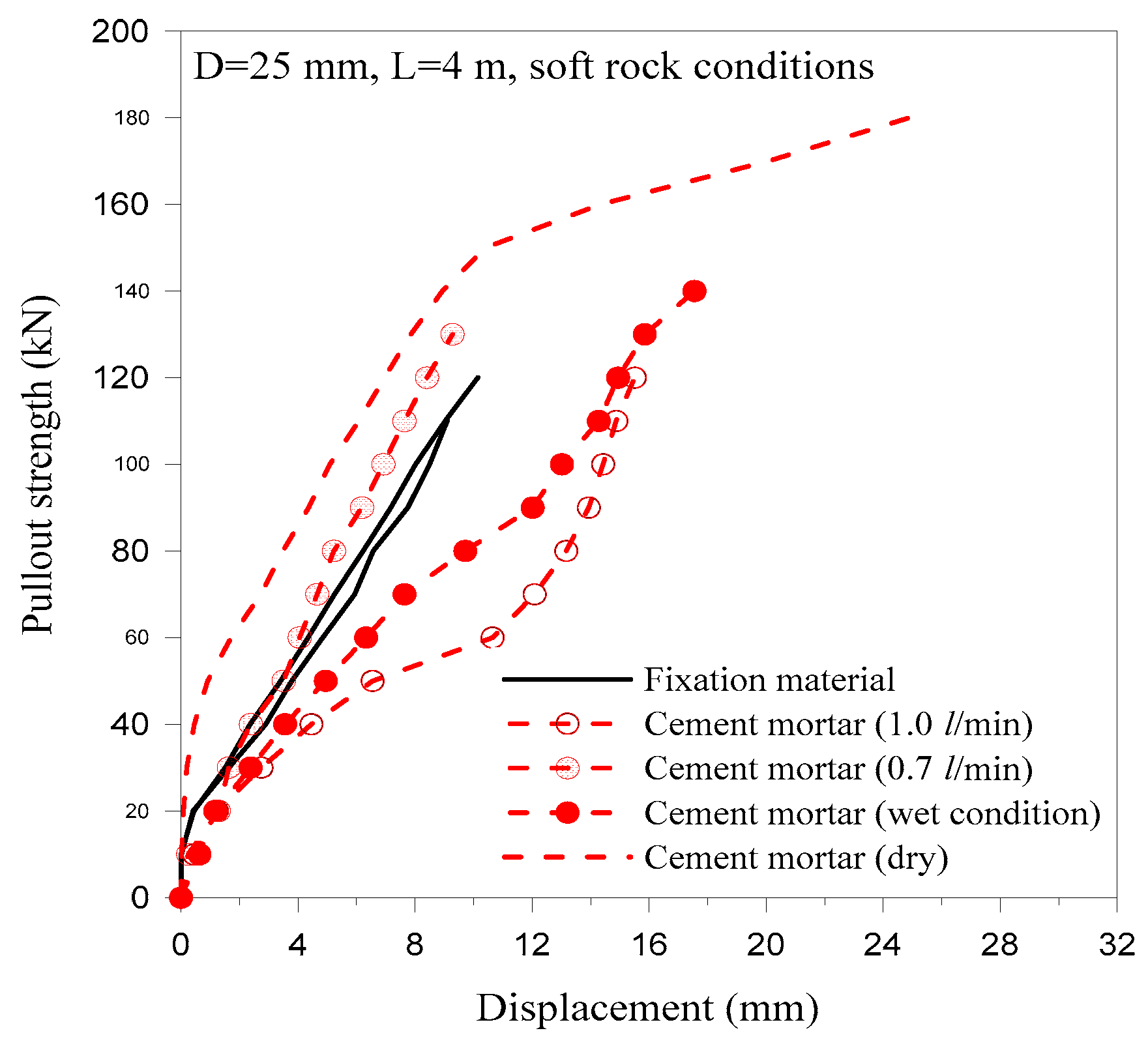
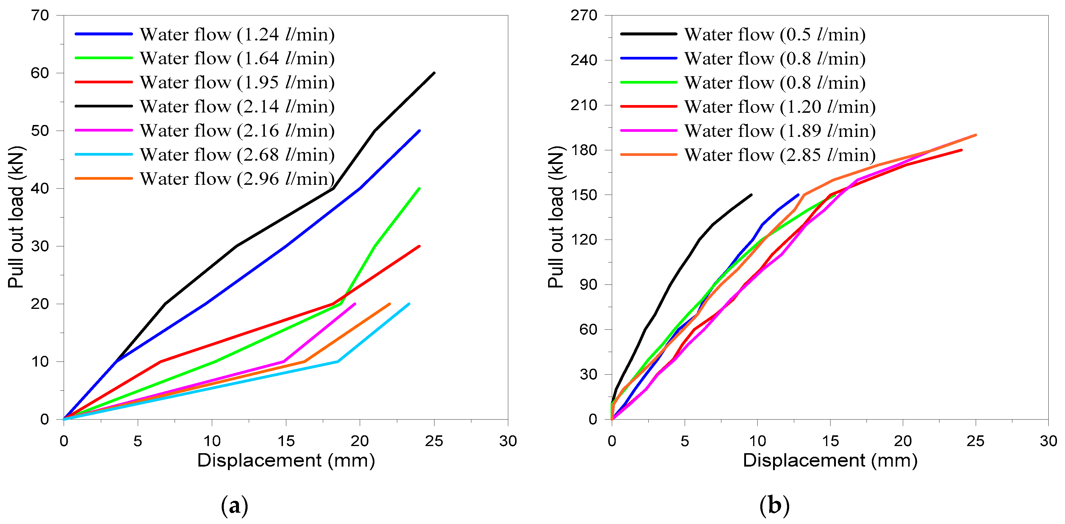
Groundwater factor is included in empirical rock-mass classification systems; however, in water-bearing rock conditions, pull-out resistance of fully grouted rock bolt is highly dependent on groundwater inflow. The effect of groundwater inflow into the borehole was investigated by carrying out the pull-out tests. For soft rock and weathered rock with a groundwater inflow of 0~3.78 L/min, rock bolts with a length of 4 m were tested. The test sections were divided into two groups, one section having slight leakage of groundwater, and the other having significant leakage of groundwater, based on the inflow rate of 1.0 L/min; the results are shown in Figure 12 and Figure 13. In water-bearing rocks, results of fully grouted rock bolts were further compared with inflated steel-tube rock bolts (ISR) for both small and large water flow for 4 m long rock bolts.

4. Discussion

Over the past few decades, the use of rock bolts for the stability of underground excavations has increased. For rock tunnel stability empirical rock-mass classification systems like, RMR, Q, and RMi, are used for preliminary support, which include rock bolts during both the design and construction. In the empirical-support design, the excavation span and rock-mass quality predict the rock-bolt pattern of 20 mm diameter fully grouted rock bolts, along with other support and reinforcement materials. The criteria for the rock-bolt pattern has been modified with time in the empirical system [59], and in its current version, the rock-bolt pattern is used in rock-mass quality calculation for the extension of the empirical system to such in situ environments that were not previously covered by these systems [13,14].
Although the applications of the empirical classification system in the tunnel-support design are widespread, in the support design, it should be noted that the application of fully grouted rock-bolt patterns are based on average values. The actual circumstances while using rock bolts in the tunnel support are not so simple that they can be predicted from the rock-mass characterization, followed by classification of supporting tunnels, using empirical systems. To design rock-bolt patterns in a safe and economical way, using empirical systems, all the factors affecting the performance of rock bolts should be evaluated. In this study, major factors are evaluated from the rock-bolt pull-out test results, as per ASTM standards for this purpose [18]. For accomplishing this task, several field tests were conducted, and the results of the previous studies are also included. Based on the field tests, laboratory test, and results from numerical modeling, the factors affecting the fully grouted rock-bolt performance are broadly divided into five types: (1) rock-bolt-related factors, (2) grout-related factors, (3) stresses, (4) rock-bolt installation, and (5) rock-mass condition.
The performance of the bolts depends on the load-transfer mechanism; the shape and type of bolt have a direct influence on this load-transfer mechanism [24]. RMR, Q, and RMi systems are based on the tunneling experience, where rock bolts are frequently used when compared to the use of cable bolts in the mining industry. Owing to ribs on the rock-bolt longitudinal profile, mechanical interlocking enhances the load-transfer mechanism. The host rock plays a significant role in the performance of fully grouted rock bolts [31], and field pull-out test results (Figure 4) indicate that, as the rock-mass quality improves, the load-carrying capacity of the rock bolt increases. Average pull-out resistance results with variation in rock-bolt length shows that the pull-out resistance increases with the length of the rock bolt for moderate rock. In soft and weathered rocks, the weak bond between the grout and bore-hole surface results in a slight change in the anchorage force with the length of rock bolt. In weathered rocks, the rock-bolt length has a negligible influence on the pull-out strength and displacement. The pull-out displacement decreases more with the increase in rock-bolt length; however, the influence of rock mass on this decrement is high. Although the load-carrying capacity of the bolt increases, this capacity should not be increased up to the ultimate tensile strength of the rock bolt [50]. In the field, different diameters of rock bolts are used, and the increase in their diameter has a linear positive impact. For the same grade of steel, the load-carrying capacity of the rock bolt increases with diameter. Although the rock bolt diameter has a positive impact on the pull-out strength and increases the ultimate tensile strength of the rock bolt, rock bolts with a large diameter are uneconomical and pose difficulties in installation. Along with the shape, length, and diameter of the rock bolt, the presence of face plate and optimum annulus space during rock-bolt installation enhances the load transfer in rock bolts from the rock mass. By increasing the diameter of the rock bolt and decreasing the annulus, evaluation from the economical point of view and installation is important.
In fully grouted rock bolts, as the annulus is filled with grout, the mechanical properties of the grout have a direct effect on the performance of the rock bolt. Although resin as grouting material has better mechanical properties than cement, the improper mixing of the chemical during rock-bolt installation decreases its efficiency. In cement grouts, the water–cement ratio has an adverse effect, and the grout’s settling time is directly related to the pull-out strength of rock bolts. The effect of these parameters is also dependent on the rock-mass quality and the pull-out strength increase for the same water–cement ratio and settling time in good-quality rock masses (Figure 7). The load-carrying capacity of rock bolt increases significantly with curing time for both moderate and weathered rock. In pull-out tests, the pull-out resistance for moderate rock increased considerably; however, load-displacement curve slope did not show any significant difference for the curing times. In the weathered rock case, curing time not only affects the pull-out resistance but also affects the gradient in the load–displacement curves. The average values for the inflection point are 57, 103, and 137 kN for 12, 24, and 36 h grout settling time, respectively, in weathered rock (Figure 7). In the case of moderate rock, these values are 73 and 150 kN for 12 and 24 h grout settling time, respectively. The literature shows that load-carrying capacity increases up to 35 days [36].
Traditional grouted rock bolts have limitations in high-stress environments, owing to their rigid nature. In high-stress in situ environments, they are unable to absorb energy. Generally, in such situations, energy-absorbing rock bolts like split set, expansion shell bolt, inflated steel-tube rock bolt, and swellex are used (Figure 2). The development of fully grouted D-bolt has replaced these traditional energy-absorbing rock bolts, owing to its high load-carrying capacity and absorbing energy [22,23]. During tunnel excavation, the installed rock bolts at different locations along the tunnel periphery behave differently, owing to the confining stresses on each rock bolt due to the induced stresses. Laboratory studies indicate that confining stresses not only increase the pull-out strength but also affect the fracturing mechanism of the rock surrounding the rock bolt (Figure 8). The field test indicates that blast-induced vibration does not affect the performance of fully grouted rock bolts and empirical classification, as well, not considering the dynamic effect as a characterizing factor. However, the wave reflection at tunnel periphery produces a negative effect on the rock-bolt performance.
The rock-support and ground-reaction curves indicate that the time of rock-bolt installation with other support and reinforcement materials has a direct effect on the support performance [60]. The installation time depends on the stand-up time, which is a function of the rock-mass quality and tunnel span [61]. The empirical system proposes a composite support, and, therefore, the stability of the composite support is essential from the economic and safety points of view. As shown in Figure 9, with the increase in radial displacement (u), the elastic limit that can be reached by one support of the composite system and its input, in terms of stiffness (ki), becomes zero. If the reinforcement/supports are supposed to be installed at the same time and distance from the excavation face, then the initial displacement for the individual support “i,” i.e., uin,i is equal to uin. The load, pi, which is applied to the generic support, i (if it has not reached its elastic limit, uel,i), becomes a function of the radial displacement (uuin) and its stiffness, ki, in Equation (13):
p i = k i × ( u u i n )
Generally, when different supports and/or reinforcements are installed at different times or at different distances from the excavation face (uin,iuin,j, for I ≠ j), the reaction line of the composite support can assume the form represented by Case 2, in Figure 9 [56].
A good rock mass has greater self-supporting capability, and thus requires less support. Moreover, in a good rock mass, the load transfer mechanism is better, and, therefore, the rock-mass quality has a positive impact on the bond strength between the grout and drilled hole’s periphery. The pull-out strength increases, and the displacement decreases, as the rock-mass quality increases. The median pull-out strength (kN) and the pull-out displacement (mm) are 127.6 and 8.545; 148.8 and 8.42; and 159.3 and 6.29, for weathered, soft, and moderate rocks, respectively (Figure 10). The median pull-out strength of the rock bolt and the empirical suggested rock load using Equation (12) indicates that the experimental results are within the range for moderate rocks. In soft and weathered rock masses, the rock-bolt pull-out strength is lower than the empirical suggested rock load (Figure 11).
In a water-bearing rock mass, groundwater has an adverse effect on the fully grouted rock bolts during the pull-out test. From four pull-out test results in slight-water-leakage soft rock, the pull-out load–displacement behavior of the fully grouted rock bolt varies irregularly with the leaking amount (Figure 12). The pull-out test results show that, in both cases of the grout materials, the pull-out strength is lower than that in the dry condition. In the case of high-leakage weathered rock, rock bolt was pulled out before yielding occurred with low pull-out load (Figure 13a). In both groundwater-leakage cases, the pull-out load–displacement curve shows no inflection point. Compared to fully grouted rock bolts, the results of the ISR showed that the inflection point of the pull-out load–-displacement curve was obvious in the presence of groundwater. The pull-out resistance of the ISR was higher than that of the fully grouted rock bolt (FGR) in slight-leakage conditions. In high-water-leaking weathered rocks, the pull-out loads of the ISR tests were considerable, even with a leaking rate of 1.2~2.85 L/min. The average pull-out resistance of the ISR under a high leaking condition was around 150 kN, which is considerably more than that of the FGR.

5. Conclusions

In this study, the proposed empirical rock-bolt pattern using RMR, Q, and RMi systems of rock-mass classification was discussed, and the rock-bolt performance was investigated. The rock-bolt performance during tunnel-support design was evaluated via pull-out test results, as per ASTM standards. The following conclusions were obtained from the study:
  • The empirical rock-mass classification system proposed 20 mm, fully grouted rock-bolt patterns during tunnel-support design, which is a function of the rock-mass quality and tunnel span. The performance of the rock bolts depends on the efficient load-transfer mechanism, which is determined through the rock-bolt pull-out test.
  • Based on the rock-bolt pull-out test, the factors affecting their performance are divided into five groups, and each group is further subdivided, and the effect of pull-out test results is discussed.
  • Certain factors, such as rock-mass quality, ground water flow, and stresses, cannot be controlled. As the rock-mass quality decreases, the length effect also decreases in the rock-bolt pull-out test due to the weak bond between the grout and drilled hole’s periphery. In the case of groundwater, inflated steel-tube rock bolts have better performance than fully grouted rock bolts.
  • Some parameters are critical for the safe and economic performance of the bolts, i.e., water–cement ratio, rock-bolt length, and time of support installation, and they should be considered in the design of the rock-bolt pattern during underground construction.
  • The overall performance of rock bolts in terms of pull-out strength is good in rock mass that is good quality, irrespective of their installation location along the tunnel periphery.
  • For the economical and efficient performance of fully grouted rock bolts, the factors investigated in this study should be considered, along with the empirical support patterns using rock-mass classification systems.

Author Contributions

H.Y. supervised the research; H.R., H.K., and W.A. developed the proposed research concept; J.K. conducted the field test and data analysis; A.M.N. and J.-j.K. reviewed the final paper and made important suggestions and recommendations for the paper’s revision.

Funding

This work was supported by the National Research Foundation of Korea Grant, funded by the Korean Government (NRF-2019R1A2C2003636).

Acknowledgments

This work was supported by the National Research Foundation of Korea grant, funded by the Korean Government (NRF-2019R1A2C2003636). The authors (Hafeezur Rehman, Wahid Ali, and Abdul Muntaqim Naji) are very thankful to the Higher Education Commission (HEC) of Pakistan for the HRDI-UESTPs scholarship. The author Jonguk Kim is supported by Seoul Institute of Technology (SIT) (19-1-3, A study on the groundwater undrainage method and monitoring of excavation work and underground infrastructure to conserve groundwater).

Conflicts of Interest

The authors declare no conflict of interest. The funders had no role in the design of the study; in the collection, analyses, or interpretation of data; in the writing of the manuscript; or in the decision to publish the results.

References

  1. Bieniawski, Z. Engineering classification of jointed rock masses. Civ. Eng. S. Afr. 1973, 15, 333–343. [Google Scholar]
  2. Bieniawski, Z.T. Engineering Rock Mass Classifications: A Complete Manual for Engineers and Geologists in Mining, Civil, and Petroleum Engineering; John Wiley & Sons: Hoboken, NJ, USA, 1989. [Google Scholar]
  3. Barton, N.; Lien, R.; Lunde, J. Engineering classification of rock masses for the design of tunnel support. Rock Mech. 1974, 6, 189–236. [Google Scholar] [CrossRef]
  4. Grimstad, E.; Barton, N. Updating the Q-System for NMT. In Proceedings of the International Symposium on Sprayed Concrete-Modern Use of Wet Mix Sprayed Concrete for Underground Support, Oslo, Norway, 22–26 October 1993; Norwegian Concrete Association: Oslo, Norway, 1993. [Google Scholar]
  5. Barton, N. Some new q-value correlations to assist in site characterisation and tunnel design. Int. J. Rock Mech. Min. Sci. 2002, 39, 185–216. [Google Scholar] [CrossRef]
  6. Palmstrom, A. Rmi-A Rock Mass Characterization System for Rock Engineering Purposes. Ph.D. Thesis, University of Oslo, Oslo, Norway, 1995. [Google Scholar]
  7. Palmström, A. Recent developments in rock support estimates by the rmi. J. Rock Mech. Tunn. Technol. 2000, 6, 1–19. [Google Scholar]
  8. Rehman, H.; Naji, A.; Kim, J.-J.; Yoo, H.-K. Empirical evaluation of rock mass rating and tunneling quality index system for tunnel support design. Appl. Sci. 2018, 8, 782. [Google Scholar] [CrossRef]
  9. Kim, J.; Rehman, H.; Ali, W.; Naji, A.M.; Yoo, H. Weightage effect during back-calculation of rock-mass quality from the installed tunnel support in rock-mass rating and tunneling quality index system. Appl. Sci. 2019, 9, 2065. [Google Scholar] [CrossRef]
  10. Lowson, A.; Bieniawski, Z. Critical assessment of rmr based tunnel design practices: A practical engineer’s approach. In Proceedings of the SME, Rapid Excavation and Tunnelling Conference, Washington, DC, USA, 23–26 June 2013; pp. 180–198. [Google Scholar]
  11. NGI. The Q-System, Rock Mass Classification and Support Design. Available online: https://www.ngi.no/eng/Publications-and-library/Books/Q-system (accessed on 9 April 2018).
  12. Windsor, C. Rock reinforcement systems. Int. J. Rock Mech. Min. Sci. 1997, 34, 919–951. [Google Scholar] [CrossRef]
  13. Lee, J.; Rehman, H.; Naji, A.; Kim, J.-J.; Yoo, H.-K. An empirical approach for tunnel support design through q and rmi systems in fractured rock mass. Appl. Sci. 2018, 8, 2659. [Google Scholar] [CrossRef]
  14. Rehman, H.; Naji, A.M.; Kim, J.-J.; Yoo, H. Extension of tunneling quality index and rock mass rating systems for tunnel support design through back calculations in highly stressed jointed rock mass: An empirical approach based on tunneling data from himalaya. Tunn. Undergr. Space Technol. 2019, 85, 29–42. [Google Scholar] [CrossRef]
  15. Palmstrom, A.; Broch, E. Use and misuse of rock mass classification systems with particular reference to the q-system. Tunn. Undergr. Space Technol. 2006, 21, 575–593. [Google Scholar] [CrossRef]
  16. Rehman, H.; Naji, A.; Ali, W.; Kim, J.; Abdullah, R.; Yoo, H. Support Design for the Diversion Tunnel of Diamer Basha Dam, Pakistan, Considering The Recent Developments in Empirical Systems; IOP Conference Series: Materials Science and Engineering; IOP Publishing: Bristol, UK, 2019; p. 012033. [Google Scholar]
  17. Bieniawski, R.Z.; Aguado, D.; Celada, B.; Rodriquez, A. Forecasting tunnelling behaviour. T T Int. 2011, 39–42. [Google Scholar]
  18. ASTMD-13e1. Standard Test Method for Rock Bolt Anchor Pull Test; ASTM International: West Conshohocken, PA, USA, 2013. [Google Scholar]
  19. Dolinar, D.R.; Bhatt, S.K. Trends in roof bolt application. In Proceedings: New Technology for Coal Mine Roof Support; NIOSH: Cincinnat, Hamilton, 2000; pp. 43–51. [Google Scholar]
  20. Moosavi, M.; Jafari, A.; Khosravi, A. Bond of cement grouted reinforcing bars under constant radial pressure. Cem. Concr. Compos. 2005, 27, 103–109. [Google Scholar] [CrossRef]
  21. Li, C. A practical problem with threaded rebar bolts in reinforcing largely deformed rock masses. Rock Mech. Rock Eng. 2007, 40, 519–524. [Google Scholar] [CrossRef]
  22. Li, C.C. A new energy-absorbing bolt for rock support in high stress rock masses. Int. J. Rock Mech. Min. Sci. 2010, 47, 396–404. [Google Scholar]
  23. Li, C.C.; Stjern, G.; Myrvang, A. A review on the performance of conventional and energy-absorbing rockbolts. J. Rock Mech. Geotech. Eng. 2014, 6, 315–327. [Google Scholar] [CrossRef] [Green Version]
  24. Kılıc, A.; Yasar, E.; Atis, C. Effect of bar shape on the pull-out capacity of fully-grouted rockbolts. Tunn. Undergr. Space Technol. 2003, 18, 1–6. [Google Scholar] [CrossRef]
  25. Aziz, N. Bolt surface profiles—An important parameter in load transfer capacity appraisal, Ground Support in Mining and Underground Construction. In Proceedings of the Fifth International Symposium on Ground Support, Perth, Australia, 28–30 September 2004; Taylor & Francis: London, UK, 2004; p. 396. [Google Scholar]
  26. Barley, A.D.; Windsor, C.R. Recent advances in ground anchor and ground reinforcement technology with reference to the development of the art. In Proceedings of the ISRM International Symposium, 19–24 November 2000; International Society for Rock Mechanics: Lisboa, Portugal, 2000. [Google Scholar]
  27. Ito, F.; Nakahara, F.; Kawano, R.; Kang, S.-S.; Obara, Y. Visualization of failure in a pull-out test of cable bolts using x-ray ct. Constr. Build. Mater. 2001, 15, 263–270. [Google Scholar] [CrossRef]
  28. Satola, I. The Axial Load-Displacement Behavior of Steel Strands Used in Rock Reinforcement; Helsinki University of Technology: Espoo, Finland, 2007. [Google Scholar]
  29. Aziz, N.; Webb, B. Study of load transfer capacity of bolts using short encapsulation push test. In Proceedings of the 2003 Coal Operators, Wollongong, Austrália, 12–14 February 2003. [Google Scholar]
  30. Signer, S.P. Field Verification of Load-Transfer Mechanics of Fully Grouted Roof Bolts; Bureau of Mines: Pittsburgh, PA, USA, 1990. [Google Scholar]
  31. Jalalifar, H. A new approach in determining the load transfer mechanism in fully grouted bolts. Ph.D. Thesis, University of Wollongong, Wollongong, Austrália, 2006. [Google Scholar]
  32. Tao, W.; Chen, C.; Jun, H.; Ting, R. Effect of bolt rib spacing on load transfer mechanism. Int. J. Min. Sci. Technol. 2017, 27, 431–434. [Google Scholar] [CrossRef]
  33. Osgoui, R.R.; Ünal, E. An empirical method for design of grouted bolts in rock tunnels based on the geological strength index (gsi). Eng. Geol. 2009, 107, 154–166. [Google Scholar] [CrossRef]
  34. Goris, J. Laboratory evaluation of cable bolt supports. In Proceedings of the 92nd Annual General Meeting of the CIM, Ottawa, ON, Canada, 6–10 May 1990. [Google Scholar]
  35. Benmokrane, B.; Chennouf, A.; Mitri, H. Laboratory evaluation of cement-based grouts and grouted rock anchors. In International Journal of Rock Mechanics and Mining Sciences & Geomechanics Abstracts; Elsevier: Amsterdam, The Netherlands, 1995; pp. 633–642. [Google Scholar]
  36. Kılıc, A.; Yasar, E.; Celik, A.G. Effect of grout properties on the pull-out load capacity of fully grouted rock bolt. Tunn. Undergr. Space Technol. 2002, 17, 355–362. [Google Scholar] [CrossRef]
  37. Kilic, A.; Anil, M. The effects of grout properties to the bolt capacity. In Proceedings of the Sixteenth Mining Congress of Turkey, Ankara, Turkey, 19–22 June 2001. [Google Scholar]
  38. Ulrich, B.F.; Wuest, W.J.; Stateham, R.M. Relationships between annulus thickness and the integrity of resin-grouted roof bolts. Report of investigations; United States. Bureau of Mines: Washington, DC, USA, 1989. [Google Scholar]
  39. Tadolini, S. The effects of reduced annulus in roof bolting performance. In Proceedings of the 17th International Conference on Ground Control in Mining, Morgantown, WV, USA, 4–6 August 1998; pp. 230–236. [Google Scholar]
  40. Li, C.; Stillborg, B. Analytical models for rock bolts. Int. J. Rock Mech. Min. Sci. 1999, 36, 1013–1029. [Google Scholar] [CrossRef]
  41. Mortazavi, A.; Tabatabaei Alavi, F. A numerical study of the behavior of fully grouted rockbolts under dynamic loading. Soil Dyn. Earthq. Eng. 2013, 54, 66–72. [Google Scholar] [CrossRef]
  42. Martin, L.B. Theoretical and Experimental Study of Fully Grouted Rockbolts and Cablebolts Under Axial Loads; Ecole Nationale Supérieure des Mines de Paris: Paris, France, 2012. [Google Scholar]
  43. Martin, L.B.; Hassen, F.H.; Tijani, M.; Noiret, A. A new experimental and analytical study of fully grouted rockbolts. In Proceedings of the 45th US Rock Mechanics/Geomechanics Symposium, San Francisco, CA, USA, 26–29 June 2011; p. ARMA 11-242. [Google Scholar]
  44. Villaescusa, E.; Varden, R.; Hassell, R. Quantifying the performance of resin anchored rock bolts in the australian underground hard rock mining industry. Int. J. Rock Mech. Min. Sci. 2008, 45, 94–102. [Google Scholar] [CrossRef]
  45. Campbell, R.; Mould, R. Impacts of gloving and un-mixed resin in fully encapsulated roof bolts on geotechnical design assumptions and strata control in coal mines. Int. J. Coal Geol. 2005, 64, 116–125. [Google Scholar] [CrossRef]
  46. Rojat, F.; Labiouse, V.; Kaiser, P. Brittle rock failure in the steg lateral adit of the lotschberg base tunnel. Rock Mech. Rock Eng. 2009, 42, 341. [Google Scholar] [CrossRef]
  47. Shiyong, W.; Manbin, S.; Jian, W. Jinping hydropower project: Main technical issues on engineering geology and rock mechanics. Bull. Eng. Geol. Environ. 2010, 69, 325–332. [Google Scholar] [CrossRef]
  48. Naji, A.M.; Emad, M.Z.; Rehman, H.; Yoo, H. Geological and geomechanical heterogeneity in deep hydropower tunnels: A rock burst failure case study. Tunn. Undergr. Space Technol. 2019, 84, 507–521. [Google Scholar] [CrossRef]
  49. Hoek, E.; Marinos, P. Tunnelling in overstressed rock. In Proceedings of the ISRM Regional Symposium-EUROCK 2009, Cavtat, Croatia, 29–31 October 2009; International Society for Rock Mechanics: Lisboa, Portugal, 2009. [Google Scholar]
  50. Kaiser, P.; Yazici, S.; Nose, J. Effect of stress change on the bond strength of fully grouted cables. In International Journal of Rock Mechanics and Mining Sciences & Geomechanics Abstracts; Elsevier: Amsterdam, The Netherlands, 1992; pp. 293–306. [Google Scholar]
  51. Stjern, G.; Myrvang, A. The influence of blasting on grouted rockbolts. Tunn. Undergr. Space Technol. 1998, 13, 65–70. [Google Scholar] [CrossRef]
  52. Jeon, S.-S.; Kim, D.-S.; Jang, Y.-W. Stability assessment of concrete lining and rock bolts of the adjacent tunnel by blast-induced vibration. J. Korean Geotech. Soc. 2007, 23, 33–45. [Google Scholar]
  53. Brady, B.H.; Brown, E.T. Rock Mechanics: For Underground Mining; Springer Science & Business Media: Berlin/Heidelberg, Germany, 2013. [Google Scholar]
  54. Siang, K.K.; Chon, C.H. Reinforcement mechanisms of rock bolt—A laboratory investigation. Geol. Soc. Malays. 2003, 46, 101–106. [Google Scholar]
  55. Spang, K.; Egger, P. Action of fully-grouted bolts in jointed rock and factors of influence. Rock Mech. Rock Eng. 1990, 23, 201–229. [Google Scholar] [CrossRef]
  56. Oreste, P. Analysis of structural interaction in tunnels using the covergence–confinement approach. Tunn. Undergr. Space Technol. 2003, 18, 347–363. [Google Scholar] [CrossRef]
  57. Unal, E. Development of design guidelines and roof-control standards for coal-mine roofs. Ph. D Thesis, The Pennsylvania State University, State College, PA, USA, 1983. [Google Scholar]
  58. Li, F.; Quan, X.; Jia, Y.; Wang, B.; Zhang, G.; Chen, S. The experimental study of the temperature effect on the interfacial properties of fully grouted rock bolt. Appl. Sci. 2017, 7, 327. [Google Scholar] [CrossRef]
  59. Rehman, H.; Ali, W.; Naji, A.; Kim, J.-J.; Abdullah, R.; Yoo, H.-K. Review of rock-mass rating and tunneling quality index systems for tunnel design: Development, refinement, application and limitation. Appl. Sci. 2018, 8, 1250. [Google Scholar] [CrossRef]
  60. Carranza-Torres, C.; Fairhurst, C. Application of the convergence-confinement method of tunnel design to rock masses that satisfy the hoek-brown failure criterion. Tunn. Undergr. Space Technol. 2000, 15, 187–213. [Google Scholar] [CrossRef]
  61. Lauffer, H. Gebirgsklassifizierung fur den stol lenbau. Geol. Und Bauwes. 1958, 24, 46–51. [Google Scholar]
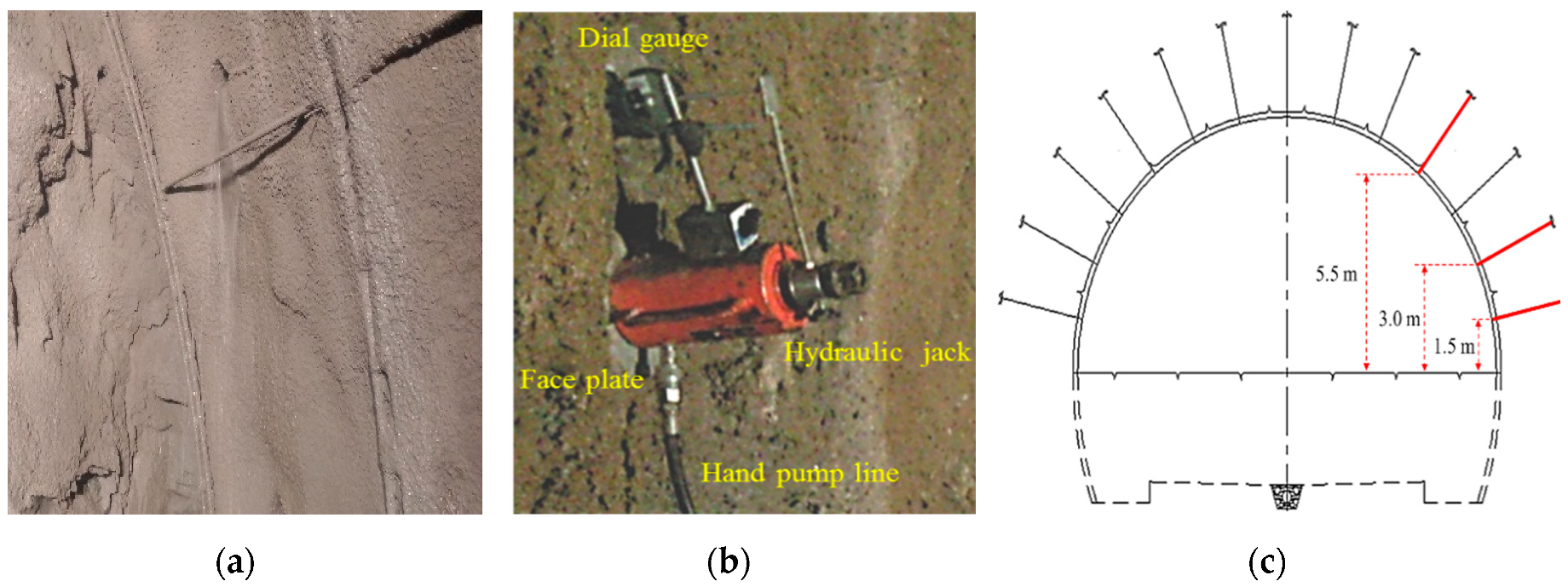
Figure 1. (a) Groundwater in flow-through drilled hole, (b) pull-out test machine, and (c) the points of pull-out test.
Applsci 09 04781 g001
Figure 2. Different types of bolts: (a) fully grouted bolt, (b) D-bolt, (c) expansion shell bolt, and (d) inflated steel-tube rock bolt [23].
Applsci 09 04781 g002
Figure 3. (a) Rock-bolt length effect on pull-out load (laboratory test) [36] and (b) pull-out displacement in different rock units (field test).
Applsci 09 04781 g003
Figure 4. Effect of rock-bolt length on pull-out strength in different rock-mass units (a) moderate rock, (b) soft rock, and (c) weathered rock.
Applsci 09 04781 g004
Figure 5. Effect of rock-bolt diameter on pull-out load [36].
Applsci 09 04781 g005
Figure 6. Effect of water–cement ratio on the pull-out strength of fully grouted rock bolt.
Applsci 09 04781 g006
Figure 7. Effect of the grout’s settling time on pull-out strength of rock bolt in (a)moderate rock and (b) weathered rock.
Applsci 09 04781 g007
Figure 8. Effect of confining pressure on borehole surrounding rock mass during pull-out test: (a) low confining stress (σ2 = σ3), (b) high confining stress (σ2 = σ3), and (c) confining stress, where σ2≠σ3.
Applsci 09 04781 g008
Figure 9. Composite support reaction lines. (a) Case 1: different support elements installed at the same time after tunnel excavation. (b) Case 2: different support elements installed at different times after tunnel excavation [56].
Applsci 09 04781 g009
Figure 10. Rock-mass quality effect in rock-bolt pull-out tests (a) in term of pullout strength and (b) in term of pullout displacement.
Applsci 09 04781 g010
Figure 11. Comparison of empirically calculated rock load with pull-out strength results in three different rock-mass types (a) moderate rock, (b) soft rock, and (c) weathered rock.
Applsci 09 04781 g011
Figure 12. Groundwater (slight leakage) effect on the performance of grouted rock bolts.
Applsci 09 04781 g012
Figure 13. Groundwater effect on the performance of (a) grouted rock bolts and (b) inflated steel-tube rock bolt.
Applsci 09 04781 g013
Table 1. Ground condition at site, based on rock-mass classification systems.
Rock-Mass Classification System Rock-Mass Class
Weathered Rock MassSoft Rock MassModerate Rock Mass
RQD<2525–5050–75
RMR<2021–4041–60
Q<0.10.1–11–10
Table 2. Numbers of field tests (in parentheses) against each parameter.
Parameter
Rock MassRock-Bolt TypeRock Bolt Length (L)Curing TimeGrout TypeGround Water Condition
Moderate (50)Fully grouted (125)L = 3 m (11)12 h (6)Mortar (103)Dry (109)
Soft (40)L = 4 m (81)24 h (6)Wet (33)
Weathered (52)inflated steel tube (17)L = 5 m (50)36 h (6)Resin (22)