Article

Enhanced Multistream Fast TCP: Rapid Bandwidth Utilization after Fast-Recovery Phase

by
Sarfraz Ahmad
* and
Muhammad Junaid Arshad
Department of Computer Science & Engineering, University of Engineering & Technology, Lahore 54890, Pakistan
*
Author to whom correspondence should be addressed.
Appl. Sci. 2019, 9(21), 4698; https://doi.org/10.3390/app9214698
Submission received: 29 August 2019 / Revised: 26 October 2019 / Accepted: 29 October 2019 / Published: 4 November 2019
(This article belongs to the Section Electrical, Electronics and Communications Engineering)

Abstract

:
The purpose of this study is to enhance the performance of Multistream Fast Transmission Control Protocol (TCP) keeping in view the recent web-based applications that are being deployed on long-range, high-speed, and high-bandwidth networks. To achieve the objective of the research study, a congestion control after fast-recovery module for congestion control scheme of Multistream Fast TCP is proposed. The module optimized the performance of the protocol by reducing the time that is required to consume the available bandwidth after a fast-recovery phase. The module is designed after studying additive-increase, multiplicative-decrease and rate-based congestion window management schemes of related transport protocols. The module adjusts the congestion window on receipt of each individual acknowledgment instead of each round trip time after the fast-recovery phase until it consumes vacant bandwidth of the network link. The module is implemented by using Network Simulator 2. Convergence time, throughput, fairness index, and goodput are the parameters used to assess the performance of proposed module. The results indicate that Enhanced Multistream Fast TCP with congestion control after fast recovery recovers its congestion window in a shorter time period as compared to multistream Fast TCP, Fast TCP, TCP New Reno, and Stream Control Transmission Protocol. Consequently, Enhanced Multistream Fast TCP consumes the available network bandwidth in lesser time and increases the throughput and goodput. The proposed module enhanced the performance of the transport layer protocol. Our findings demonstrate the performance impact in the form of a decrease in the convergence time to consume the available network bandwidth and the increase in the throughput and the goodput.

1. Introduction

Most of the internet applications are being deployed on long-range, high-speed, and high- bandwidth networks. Fast-paced data transfer over high-speed communication systems is the primary issue raised in long-range and high-bandwidth networks. Transmission Control Protocol (TCP) [1] transmits enormous data traffic globally [2]. Although, TCP provides reliable data transmission over the network at its inception, it was not capable of handling network blockage. Jacobson proposed a congestion management scheme in 1988 [3] to overcome this limitation. Researchers improved the Jacobson’s congestion management scheme through several enhancements [4,5,6,7,8,9], but still, it can be further improved. TCP demonstrated exceptional performance over internet with the increase in size, speed, load, and connectivity. But loss-based congestion control schemes degrade TCP’s performance in high-bandwidth-delay product networks. Delay-based congestion control schemes solved the limitation of loss-based congestion control schemes in high-bandwidth-delay product (BDP) networks [10]. TCP Vegas [11] and Fast TCP [10,12] are examples of delay-based transport protocols.
All TCP variants serialize the applications’ independent messages over a single byte stream for data transmission across the network. This phenomenon becomes the reason of the head-of-line blocking [13]. Multistream Fast TCP (MFast TCP) provides a separate stream for each independent message of the application and interleaves each stream’s segments over a single TCP connection to fix the head-of-line blocking problem [14]. This procedure alleviates the head-of-line blocking but does not affect the end-to-end throughput which can be increased through optimization of the congestion management scheme.
Congestion management schemes [15] maintain smooth data flow, but do not provide assurance that data segments will not be lost during the data transmission across the network. The segment loss degrades TCP’s performance. Therefore, the research community is still improving TCP congestion control schemes by focusing on its four intertwined phases that are: slow start phase, congestion avoidance phase, and fast-retransmit and fast-recovery phases [8,9,16].
Congestion control schemes increase the size of the congestion window (cwnd) after fast-recovery mode. This change should neither be too slow nor be too fast. In case of slow change in the congestion window, TCP does not use the available bandwidth efficiently and the fast change may create network congestion. Different TCP versions use different techniques to set the congestion window size after fast-recovery mode. The precise change as per the availability of bandwidth in the congestion window size after fast-recovery mode can increase the end-to-end throughput.
MFast TCP and Fast TCP use their conventional approach to adjust their congestion windows. The approach is to re-compute the congestion window size on each round trip time (RTT) during congestion avoidance and also after fast-recovery mode. This approach takes significant time to consume the vacant network bandwidth after fast-recovery mode.
This study proposes an algorithm to adjust the congestion window on each acknowledgment (ACK) after the fast-recovery phase until it consumes the available space of the network link. The algorithm performs the task in significantly less time. Consequently, the performance of MFast TCP is improved due to the decrease in convergence time after fast recovery and increase in end-to-end throughput and goodput.
Simulation results showed that Enhanced Multistream Fast TCP (EMFast TCP) after fast recovery consumes available bandwidth in 29% less time compared to Fast TCP and MFast TCP and 52% less time compared to a Stream Control Transmission Protocol (SCTP), which follows additive-increase multiplicative-decrease (AIMD) behavior.
The remaining research paper is arranged as follows. In Section 2, we discuss the background for this research study. In Section 3, we describe EMFast TCP and congestion Control after fast-recovery (CCaFR) algorithm. In Section 4, the simulation setup is described. In Section 5, results are presented, analyzed, and discussed. Section 6 concludes the research study.

2. Background

TCP that is described in Request for Comments–793 (RFC-793) [1] uses retransmission timeout (RTO) to ensure reliable delivery of every segment. This TCP version is not capable of handling network congestion. Therefore, congestion collapse occurred in 1986. Van Jacobson fixed this problem and proposed a congestion control algorithm [3]. This algorithm controls data transfer rate through a congestion window to control network congestion. It increases the congestion window on each positive acknowledgment, does not change the congestion window on duplicate acknowledgment, and reduces its size to 1 segment when packet drop occurs. The algorithm proposed by Jacobson is implemented in TCP Tahoe. Tahoe starts the RTO timer before handing over the segment to the Internet Protocol (IP) layer. It follows a slow-start procedure at the time of connection establishment and packet loss. In slow-start, the congestion window is set to one and gradually increases after each round trip time. It uses the retransmission timeout as a sign of packet loss and consequently sets the congestion window to one. The major drawback of Tahoe is that it takes a complete timeout interval (RTO) to detect packet loss. Therefore, the network pipe becomes empty. Although RTOs help to recover network congestion, they cause serious network stalls and performance degradation [17]. TCP Reno [18] addressed this problem.
TCP Reno inherits basic features from Tahoe such as slow start, congestion avoidance, and RTO. However, it further incorporated a mechanism to detect packet loss much earlier than RTO so that the pipe emptiness could be avoided at the time of packet loss. Reno requires that the receiver generate acknowledgment on receipt of each segment. Therefore, in its implementation, receiver generates duplicate acknowledgment on receipt of out-of-order segment. Duplicate acknowledgment has twofold purposes for the sender: (i) The receiver has received the segment, and (ii) the received segment is out-of-order. Reno suggests the fast -retransmit algorithm. The fast-retransmit procedure infers from three consecutive, duplicate ACKs that a packet has been lost. Therefore, it retransmits the segment without waiting for the RTO to occur. Thus, it retransmits the segment with the pipe almost full. Reno introduced another algorithm called ‘fast recovery’ which works along with fast retransmit. Fast retransmit dispatches the lost segment on third duplicate acknowledgment and hands over the control to the fast-recovery procedure. In fast recovery, the congestion window is reduced to half.
Fast-retransmit and fast-recovery procedures [9] are shown in Figure 1. The figure shows that sender dispatches packet#1 that is successfully received and acknowledged by the receiver. Receiver dispatches dupAck#1 to the sender on receiving an out of order packet#3. When the sender receives third dupAck#1, it infers that the packet has been dropped. Fast retransmit dispatches lost packet#1 on receipt of third dupAck#1 to repair the loss. The fast-retransmit scheme works in parallel with RTO scheme for performance improvement.
Fast recovery starts monitoring the data transfer right after the dispatch of the lost segment until the receipt of a non-duplicate ACK. It sets threshold value (ssthresh) to one-half of the current window size and sets the congestion window to ssthresh plus 3. It increases the congestion window by the number of segments that have left the network and are cached on the other end. On receipt of each dupAck, it increases the congestion window by one. This inflates the congestion window for additional segments considering that duplicate acknowledgment is an indication that one segment has left the network. With this technique, the TCP sender transmits a new data segment while waiting for the acknowledgment of the lost segment. Therefore, it transmits the new data segment and maintains total segments in flight (TSF) upto the ssthresh computed by the fast-recovery procedure. TSFs are those segments which are not acknowledged so far. In normal conditions, TSF is the same as cwnd. But in the fast-recovery phase, it is different from cwnd. The algorithm sets the congestion window to ssthresh on receipt of acknowledgment of new data and quits from the fast-recovery phase.
Assume cwnd = N, where N is the size of the congestion window. A pcket in left edge of the congestion window say packet#i is lost. Now, the sender can send up to packet#(I + N − 1). Meanwhile, the receiver will send N − 1 dupAck. The sender computes TSF = N − 3 on receipt of third dupAck (at this point, cwnd = N/2 + 3, that is different from TSF). It means three later packets are no longer in flight. The sender transmits the lost packet immediately. The sender now expects N − 4 more dupAcks followed by one new acknowledgment from the receiver. This last acknowledgment will be for the entire original congestion window that was before the loss of the packet.
The sender waits for N/2 − 3 more dupAcks to arrive, at this point, TSF is N − 3 − (N/2 − 3) = N/2. The sender will resume sending new packets afterward. It will send one new packet for each subsequently arriving dupAck. This new data transmission will be from N + i to (N + i) + (N/2 − 1).
At the time of receipt of acknowledgment of retransmitted lost packet, there are N/2 − 1 unacknowledged packets from N + i to N + i + (N/2 − 2) in the pipe. At this point, the cwnd is N + N/2 − 1 and the sender can now send segment #(N + i) + (N/2 − 1). There is exactly N/2 outstanding segments. The congestion window is set to N/2 and the fast-recovery period is over now. This whole phenomenon is shown in Figure 1.
After fast recovery, TCP gradually increases its cwnd as shown in Figure 2.
Loss-based congestion control protocol uses additive increase to increase the congestion window; whereas delay-based congestion control protocol uses a formula to change its congestion window. This change in the congestion window gradually fills the gap.
TCP Vegas is a modified implementation of Reno, and Fast TCP is a high-speed version of Vegas. Fast TCP inherits all the features of Tahoe and Reno that is retransmission timeout, fast retransmit, and fast recovery. It uses a proactive approach (delay-based congestion control) instead of a reactive approach (loss-based congestion control) to control network congestion. It uses queuing delay along with packet loss as a congestion indicator. It follows an equation-based scheme (as given in Equation (1)) to compute the congestion window to stabilize a network into a steady state.
w   m i n { 2 w ,   ( 1 γ ) w + γ ( b a s e R T T R T T w + α ) }   ,
where γ ε (0, 1], baseRTT is the smallest round trip delay observed so far, and α is a positive protocol parameter that determines the total number of packets queued in routers in equilibrium along the flow’s path.
TCP and all its variants transfer data over its single byte stream. Recent applications have to transfer multiple independent messages. These applications serialize the multiple independent messages over the single byte-stream of TCP for data transmission. During transmission, if a packet loss occurs, then data delivery to the application stops. In this scenario, TCP suffers head-of-line blocking. Multistream Fast TCP (MFast TCP) [19] is derived from Fast TCP. It provides multiple streams at the transport layer for simultaneous transmission of applications’ multiple independent messages. Its multistream feature enables the protocol to differentiate between independent messages/streams received from application layer protocol. This feature reduces data delivery latency between transport and application layer and alleviates head of line blocking. MFast TCP utilizes high bandwidth, consumes less buffer space, and avoids large queuing delay, in contrast to loss-based congestion control schemes. It accomplishes relative fairness and does not punish flows with huge RTTs [10,12,20,21].
Stream Control Transmission Protocol [22] is a transport protocol designed to overcome TCP’s limitations for telephony signaling over IP network. It provides two unique features that are multistreaming and multihoming. Multistreaming is used to provide logically separate streams to the application to transfer its multimedia object data simultaneously at transport layer. Multihoming provides fault tolerance to the application on multihomed end hosts. This protocol uses a loss-based congestion scheme. This scheme with AIMD is not scalable in long-distance and high-bandwidth networks [23].
Delay-based congestion control technique tries to maintain consistent inter-packet delay during congestion avoidance phase. Inter-packet delay (IPD) jitter of MFast TCP is shown in Figure 3.
Figure 3 shows considerable IPD jitter in slow start phase. During the congestion avoidance phase, there is no inter-packet delay variation as shown by the straight horizontal line in the figure. Delay information in delay-based congestion control algorithms permits the sources to settle into a stable state when the network is static.
We intentionally dropped a single packet to trigger the fast-retransmit and -recovery procedure. The fast retransmit procedure retransmits the dropped packet; whereas the fast-recovery procedure maintains the packet in flight equal to the size of half of the congestion windows. After packet loss, inter-packet delay is disturbed as shown by IPD jitter in Figure 3 near the 38th second of this simulation. In order to maintain consistent IPD, MFast TCP gradually increases its congestion window on each RTT to decrease IPD jitter. The zoom in view during and after the fast-retransmit and -recovery procedure is extracted from Figure 3 and shown in Figure 4.
Figure 4 shows that IPD jitter gradually decrease with the increase in cwnd size. When the MFast TCP fills the available network bandwidth, IPD becomes consistent. MFast TCP changes its cwnd on each RTT as per the network feedback. It does not change its congestion window on each valid ACK.
Fast TCP and MFast TCP update their cwnd on each RTT, and they adopt the same phenomenon after the fast-recovery phase. In this study, we proposed to change the cwnd of MFast TCP after fast-recovery phase on each ACK by using Equation (1) until the IPD becomes consistent. Consistent IPD means the available bandwidth has been fully consumed. The proposed change enhanced the performance of MFast TCP with decrease in convergence time after fast recovery and increase in end-to-end throughput and goodput.

3. Enhanced Multistream Fast TCP (EMFast TCP)

In this section, we extend the Fast TCP congestion control algorithm to resolve the issue of rapid convergence after the fast recovery in long-distance and high-bandwidth network. Further, it narrates the CCaFR algorithm.

Congestion Control after Fast-Recovery Algorithm (CCaFR)

CCaFR algorithm becomes active after the fast-recovery phase until the protocol consumes the available network bandwidth. The CCaFR algorithm inherits default Fast TCP design. Therefore, the default parameters of Fast TCP are used in the development of this algorithm. CCaFR changes the congestion window on receipt of each ACK until the available bandwidth of network link is filled and IPD becomes consistent.
CCaFR computes the congestion window using Equation (1) and is denoted as cwndnew and the congestion window before this computation is referred to as cwndold (congestion window computed on receipt of last acknowledgment). Gapflag is a pointer which becomes true as the first gap between the series of acknowledgment is detected. The formula to compute the congestion window on receipt of each ACK is shown in Equation (2):
c w n d     { c w n d t e m p = c w n d o l d + ( 1 c w n d o l d ) i f ( g a p f l a g = t r u e )   c w n d n e w   e l s e   c w n d t e m p }   .
The CCaFR algorithm is described in Algorithm 1. Congestion control algorithm sets the value of isAFRmode (is after fast-recovery mode) true while leaving the fast-recovery mode. If the value of isAFRmode flag is true, it means that the fast-recovery mode has just finished, and the protocol has to increase its cwnd to consume the vacant network bandwidth.
Algorithm 1. Growth of congestion window on receipt of each ACK in CCaFR.
Input: (AckPacket, rtt)
Output: cwnd_
1IF isAFRmode = true THEN
2  IF avgIPD = IPD and avgRTT = rtt THEN
3    isAFRmode ← false
4    gapflag ← false
  END IF
5  IF gapflag = true THEN
    fast_cc_afr(rtt, old_pif) ∇ change cwnd as per its default delay-based scheme
6  ELSE
    cwnd_ = cwnd_ + 1/cwnd_
  END IF
7  IF avgIPD = IPD THEN
    gapflag ← true;
8  END IF
ELSE
9  fast_cc(rtt, old_pif) ∇ change cwnd as per its default delay-based scheme after each RTT
END IF
  return cwnd_
Line by line description of the algorithm is as follows:
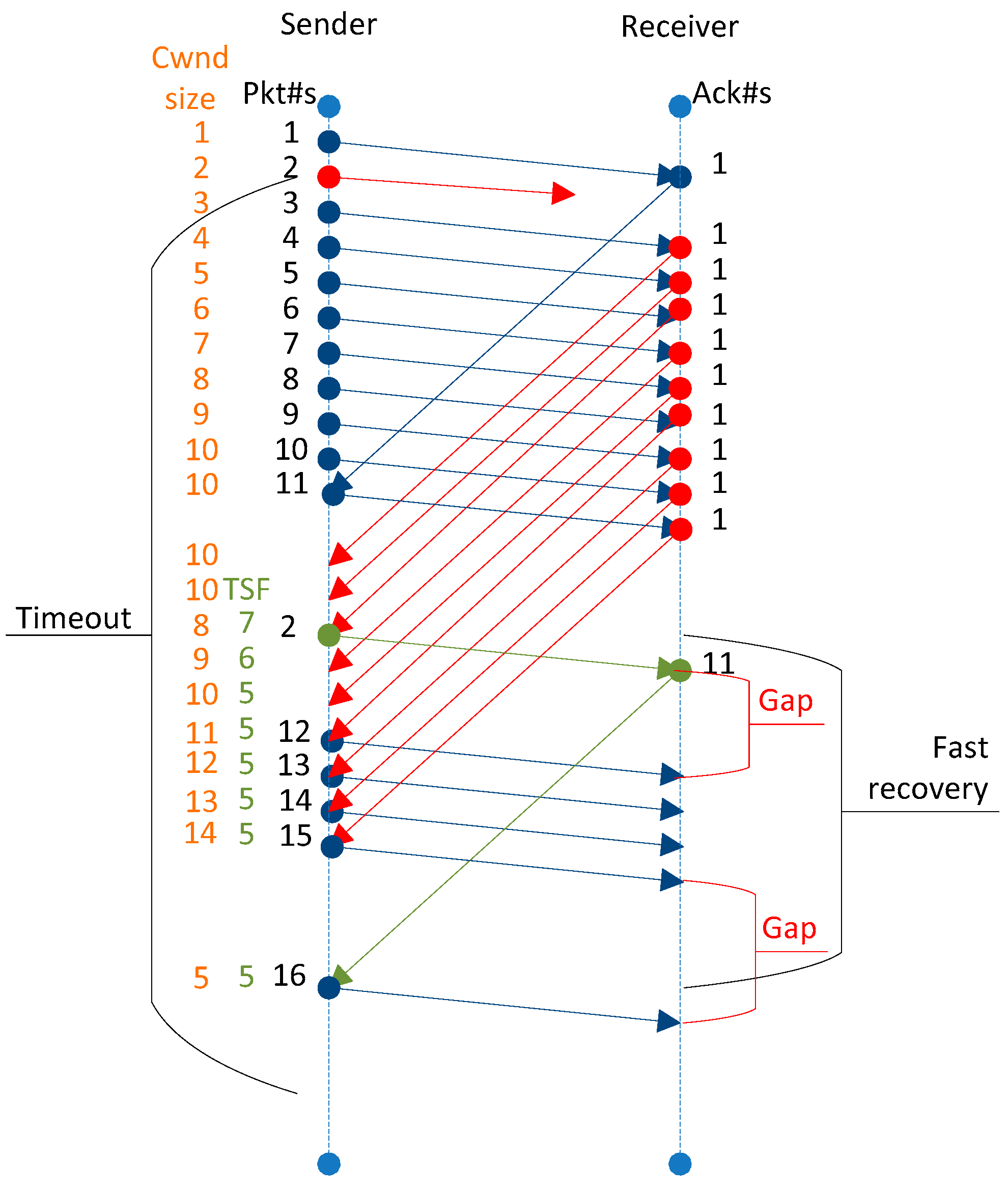
  • Did the protocol just exit from the fast-recovery mode? If so, then introduce new segments in the network to increase the congestion window.
  • If the average inter-packet delay is equal to the inter-packet delay of the received segment and the average round-trip-time is equal to the round-trip-time of the received segment, it means the protocol has consumed all the available bandwidth of the network link. Therefore, it is appropriate to quit isAFRmode and let the protocol operate in normal mode.
  • Set the value of isAFRmode to false so that on receipt of the next segment, the protocol does not execute the CCaFR algorithm.
  • Gapflag is the pointer to detect the gap between the series of segments, being received on the sender’s end.
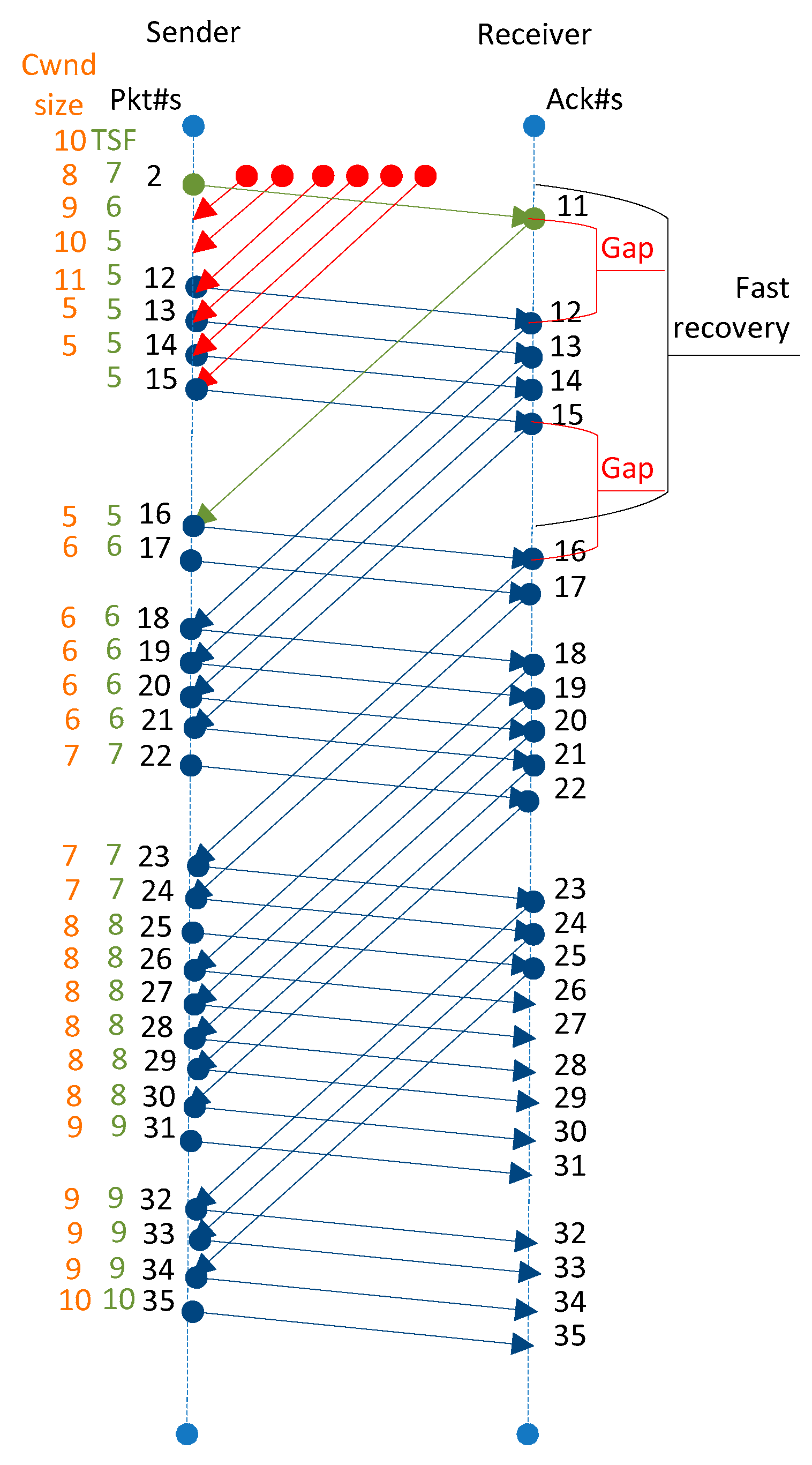
  • If the first series of the segment has already been received and the protocol is now receiving the second series of segments, then use the protocol’s default formula to compute the cwnd based on the information of received segment’s RTT and old packets inflight. The function fast_cc_afr is used to compute the congestion window on receipt of each acknowledgment.
  • If the first series of the segments are being received by the sender, then increase its congestion window using additive-increase formula. This technique is used here to provide sufficient time to the network to clear its congestion.
  • If the average inter-packet delay is equal to the inter-packet delay of the received segment, then the gapflag value is set to true so that the protocol could increase its congestion window by using its delay-based formula.
  • Body of if condition given at line 1 ends here.
  • Now, the protocol is in normal congestion avoidance phase. Therefore, it is calling fast_cc function that is a part of Fast TCP implementation. This function calculates congestion window after every round-trip-time (RTT). This is the normal behavior of the protocol.

4. Simulation Setup

This section illustrates the experimental setup and the network topology. Goodput, throughput, and convergence time are the parameters used to measure the performance of the proposed algorithm.

4.1. Experimental Setup and Network Topology

The simulation is performed with the Network Simulator 2 (ns-2) version 2.35. We used Fast TCP patch fast-tcp-ns2-v1_1c; developed at the University of Melbourne’s Center for Ultra-Broadband Information Networks (CUBIN) [24] to implement our proposed algorithm as discussed in a previous section.

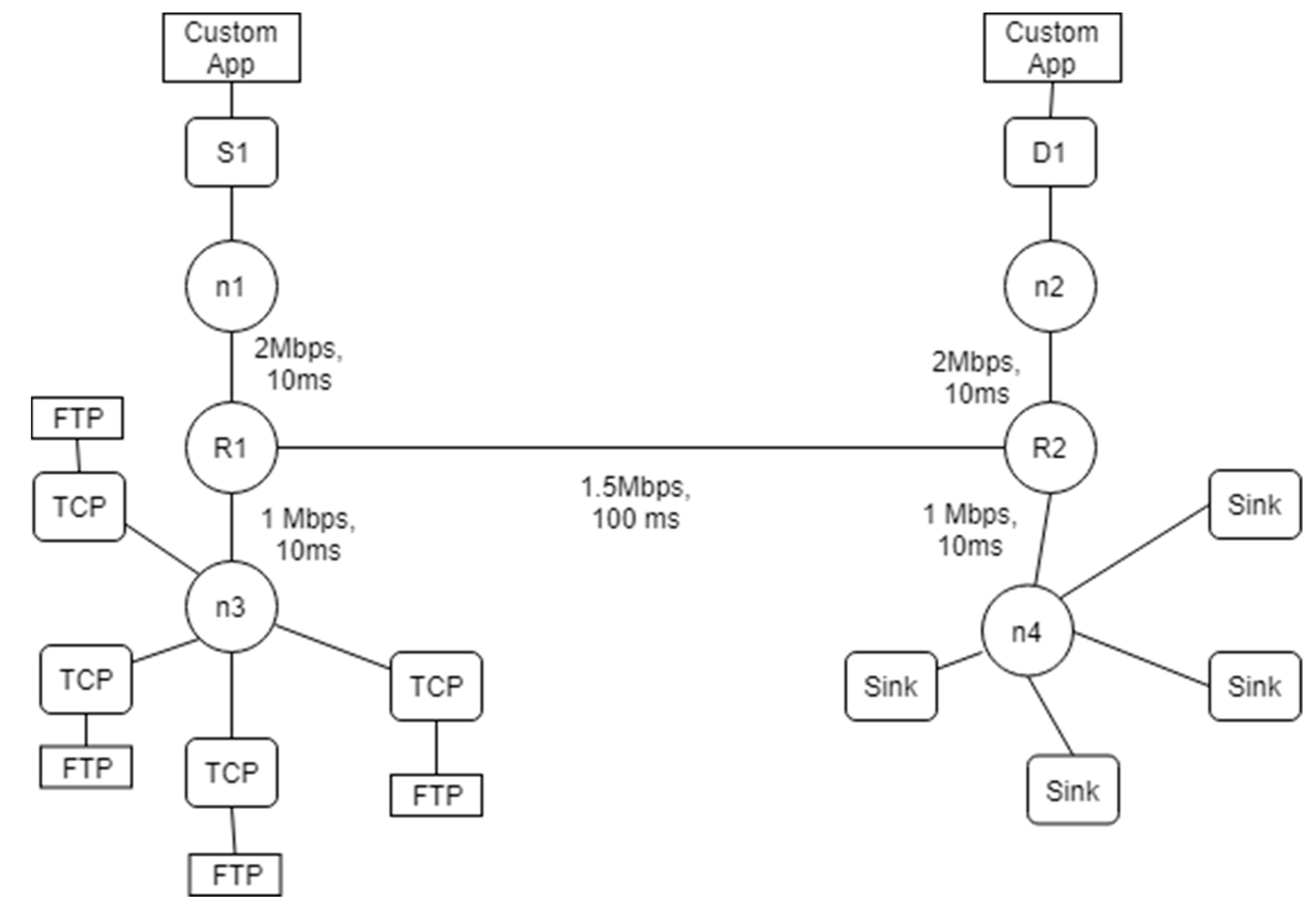
4.1.1. Network Topology

The network topology of six nodes is shown in Figure 5. Sender S1 is attached with n1 and receiver D1 is attached with n2. There are two intermediate routers R1 and R2. Duplex links n1–R1, n3–R1, R1–R2, R2–n4, and R2–n2 have bandwidth of 2, 1, 1.5, 1, and 2 Mbps and delay of 10, 10, 100, 10, and 10 ms, respectively. Each node uses a DropTail queue of size 10. Fast TCP, MFast TCP, EMFast TCP, TCP New Reno, and SCTP are the agents attached at the sender node (S1) one by one to study the behavior of these protocols while executing simulation scenarios. The simulation is run for 100 sec. An error model is attached with the link n1–R1 to drop a packet to monitor the behavior of transport protocol after the fast-recovery and to study its impact on goodput and throughput.

4.1.2. Evaluation Method

The simulation experiments were performed to analyze the behavior of EMFast TCP after the fast-recovery phase and the results were compared with Fast TCP, MFast TCP, TCP New Reno, and SCTP. We desired to calculate the convergence time of the transport protocols after the fast-recovery phase to see its impact on goodput and throughput in comparison with the proposed algorithm. An error-model was used to introduce packet loss. The packet was completely removed from the system; so, the receiving node could not receive the specific packet. This created a gap in the sequence number on the receiver’s side and the data was received out of order. This phenomenon triggers the fast-retransmit phase following the fast-recovery phase. After the fast-recovery phase, the protocols increased their congestion window as per their algorithm to consume the available bandwidth of the network link.
Each simulation experiment was repeated five times to collect the data, and average values were used to compare the performance of EMFast TCP with other protocols. In the first experiment, independent traffic for EMFast TCP, Fast TCP, MFast TCP, TCP Reno, and SCTP was generated without any other traffic/flow. This scenario was created to study the behavior of the protocols in isolation. In this experiment, Fast TCP, MFast TCP, TCP New Reno, and SCTP were using their default algorithm to manage their congestion window after the fast recovery. In second experiment, four additional flows of TCP New Reno were generated along with the traffic of protocols that are under study. In these experiments, we investigated the convergence time, fairness index, end-to-end goodput, and throughput.

5. Results and Discussion

This section illustrates the different graphs and descriptive results.

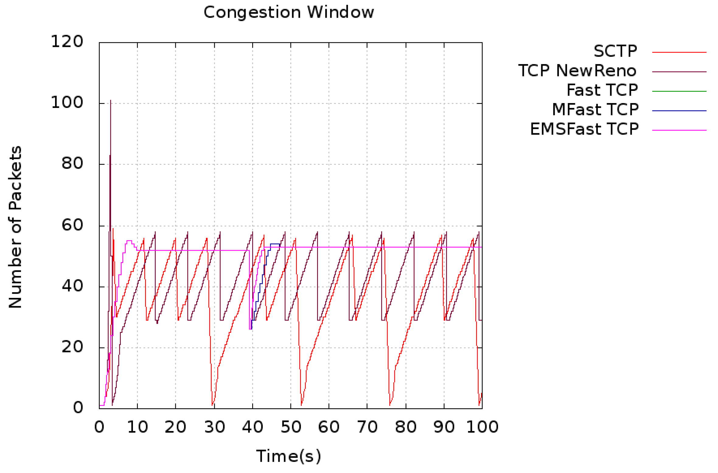
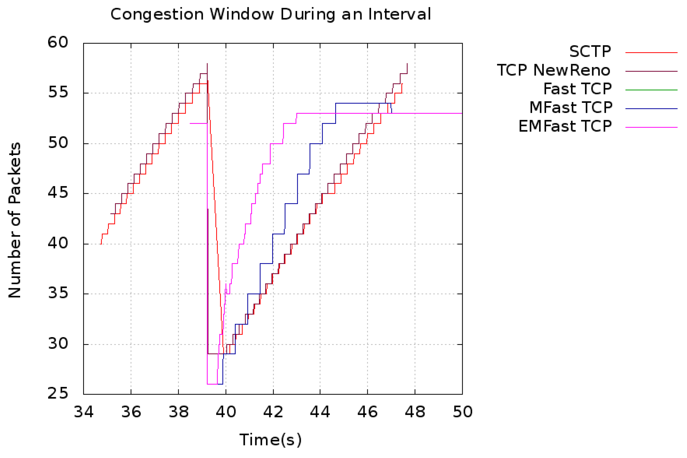
5.1. Convergence Time

Figure 6 shows the congestion window variation of Fast TCP, MFast TCP, EMFast TCP, TCP New Reno, and SCTP during the simulation period. SCTP and TCP New Reno due to their loss-based congestion control algorithm drop multiple packets during the transmission, whereas ast TCP, MFast TCP, and EMFast TCP maintain their congestion window during the simulation period. The size of their congestion window is reduced due to the packet loss. This packet loss is introduced by the error model.
The congestion windows of SCTP and TCP New Reno fluctuate during the simulation period. This fluctuation is due to the loss-based congestion control algorithm. Fast TCP, MFast TCP, and EMFast TCP maintain their congestion windows because of the delay-based congestion control algorithm. The protocols reduce the congestion window at the time packet of loss. Fast TCP and MFast TCP showed exactly the same behavior. Therefore, the lines in the graph representing these protocols overlap each other. In the absence of competing flows, the protocols consume all available bandwidth of the network and provide maximum throughput as allowed by their algorithms.
Four flows are introduced with each individual flow of the protocol under study to further observe the behavior of the protocols in the presence of competing flows. The protocols accommodate the additional flows and adjust their own congestion windows accordingly. Fast TCP, MFast TCP, and EMFast TCP are sensitive to network delay. Therefore, they adjust their congestion windows considering the network state. These protocols are not so greedy toward network queues; therefore, they easily accommodate new data flows by adjusting their data transfer rate. This phenomenon can be seen in Figure 7.
In order to get a closer view, a portion of the congestion window graph from Figure 6 and Figure 7 is extracted in Figure 8 and Figure 9, respectively.
The figures show the portion of the congestion window graphs, to highlight the interval in which the packet is lost and how the protocols consume the available bandwidth of network link after the fast recovery. We overlapped the congestion window graphs (during the period of packet loss) of all the protocols within a same time interval for better analysis. Figure 8 and Figure 9 show that EMFast TCP consumes the available network link after the fast recovery more rapidly than Fast TCP, MFast TCP, TCP New Reno, and SCTP.
EMFast TCP provides better performance compared to the rest of the protocols under study in the presence or absence of competing flows. It consumes the available network bandwidth in a minimum convergence time compare to rest of the protocols.
EMFast TCP consumed the available network link in 9 RTT, as shown in Figure 10; whereas MFast TCP and Fast TCP were performing the same task in 17 RTTs as shown in Figure 4.
Convergence time (T) is the time taken by the flow to gain a fair share of the available bandwidth of network link. Our focus is on the convergence time after the fast-recovery phase. Convergence time is calculated by using Equation (3). Where TPD represents the time of receiving the third duplicate acknowledgment and TLF represents the time when the protocol regains the fair share of the available bandwidth of network link after fast-recovery phase.
T = TLF − TPD
The convergence time of the protocol after fast recovery without any additional flow is shown in Table 1. In this scenario, Fast TCP, MFast TCP, EMFast TCP, TCP New Reno, and SCTP attain a maximum congestion window of size 52, 52, 52, 57, and 56, respectively. EMFast TCP attains its congestion window size to consume available bandwidth in 29% less time compared to the Fast TCP and MFast TCP, 54% less time compared to TCP New Reno, and 52% less time compared to the SCTP. The 29% improvement is due to the CCaFR algorithm whereas 52% and 54% are the cumulated effect of delay-based congestion control algorithm and CCaFR algorithm.
Convergence time of the protocol after fast recovery with four additional flows is also shown in Table 1. In this scenario, Fast TCP, MFast TCP, EMFast TCP, TCP New Reno, and SCTP attain a maximum congestion window of size 27, 27, 27, 34, and 32, respectively. EMFast TCP consumes available bandwidth in 55% less time compared to the Fast TCP and MFast TCP, 74% less time compared to TCP New Reno, and 73% less time compared to the SCTP. This is because it quickly re-acquires a small congestion window compared to the large congestion window size of SCTP and TCP New Reno.
Therefore, EMFast TCP with CCaFR algorithm improves the performance in terms of congestion window recovery after the fast-recovery phase in long-distance networks. Thus, it is concluded that CCaFR improves the performance of the protocol in a network where there is a high loss rate.

5.2. Throughput

The amount of data successfully received at the destination in a given period of time is called throughput. This data includes the retransmitted packets.
Throughput = (∑Packets received × Packet Size)/Total Simulation Time
The decrease in the convergence time after the fast-recovery phase affects the end-to-end throughput. EMFast TCP achieves higher throughput as compared to Fast TCP, MFast TCP, TCP New Reno, and SCTP. Table 2 shows the throughput of EMFast TCP, Fast TCP, TCP New Reno, and SCTP with and without additional flows. Results show that EMFast TCP provides better throughput by using CCaFR as compared to Fast TCP, MFast TCP, TCP New Reno, and SCTP.

5.3. Goodput

The number of useful data bytes handed over to the application layer by the transport layer in a unit time is called goodput. Goodput is computed by using Equation (5).
Goodput = (Sent Data − Retransmitted Data)/Transfer Time
End-to-end goodputs of the protocols are shown in Table 3. All these three protocols have a common feature that is multistream except TCP New Reno. With this feature, these protocols can handle multiple independent requests of their applications. The multistream feature resolves the issue of head-of-line blocking and provides data to the application during the period of fast retransmit and recovery. TCP and all its variants stop data delivery to the application layer during the period of packet loss until the receipt of the lost packet. MFast TCP and EMFast TCP overcome this limitation of TCP. It is quite clear from Table 3 that MFast TCP and EMFast TCP provide better performance compared to SCTP and TCP New Reno, whereas EMFast TCP due to CCaFR algorithm further improves the performance, as compared to MFast TCP.
It is necessary to mention that Fast TCP without the multistream feature, extensively utilizes the receiver buffer during the fast-retransmit and -recovery phases. MFast TCP takes significant time to recover its cwnd after the fast-recovery phase whereas the EMFast TCP overcomes this issue through its CCaFR algorithm, and its impact can be seen in the end-to-end goodput.

5.4. Fairness Index

Jain’s formula [25] as given in Equation (6) was used to determine the fairness index of the transport protocols being studied. The protocols that are understudy are associated at flow-1 on their turn whereas flow-2 to flow-5 are additional flows introduced in the network.
F a i r n e s s   I n d e x   =   ( x i ) 2 n   x i 2
As shown in Table 4, the fairness indexes of SCTP, Fast TCP, TCP New Reno, and EMFast TCP are 0.9221, 0.9338, 0.9296, and 0.9328, respectively. Native Fast TCP has the best fairness index value among the four transport protocols. Since, EMFast TCP improves overall throughput of its flow, its fairness index is slightly lesser than that of Fast TCP. The behavior of EMFast TCP only deviates from the native Fast TCP behavior after the fast-recovery phase. Therefore, there is a slight variation in its fairness index compare to that of native Fast TCP.

6. Conclusions

Optimization of the congestion control algorithm is an area that continues to attract the attention of researchers. The motivation of this study is to reduce the time required to consume the available bandwidth after the fast-recovery phase for Fast TCP/MFast TCP. Therefore, the CCaFR algorithm is found suitable for the transport protocols that operate in high-bandwidth and long-distance networks. The obtained results and their analysis illustrated that the CCaFR algorithm positively outperformed Fast TCP/MFast TCP (delay-based congestion control schemes) and TCP New Reno and SCTP (loss-based congestion control schemes). This indicates that CCaFR is more suitable for the protocol that adjusts their congestion window on each RTT. The proposed algorithm can be used for the protocols that use delay as congestion indicator and adjust their congestion window on each RTT.

Supplementary Materials

The following are available online at https://www.mdpi.com/2076-3417/9/21/4698/s1. Table S1: Convergence time of the protocols after fast recovery phase. (Test # 1 to 5), Table S2: End-to-end throughput of the protocols (Test # 1 to 5), Table S3: End-to-end goodput of the protocols (Test # 1 to 5).

Author Contributions

S.A. proposed the algorithm, implemented it in NS2, analyzed the results and wrote the paper. M.J.A. supervised this research work and reviewed the paper.

Funding

This research received no external funding.

Conflicts of Interest

The authors declare no conflict of interest.

References

  1. Postel, J. Transmission Control Protocol; RFC-793; Internet Engineering Task Force (IETF): Fremont, CA, USA, 1981. [Google Scholar]
  2. Shivaranjani, M.; Shanju, R.; Jude, M.J.; Diniesh, V.C. Analysis of TCP’s micro level behaviour in wireless multi-hop environment. In Proceedings of the IEEE International Conference on Computer Communication and Informatics (ICCCI), Coilmbatore, India, 7 January 2016. [Google Scholar]
  3. Jacobson, V. Congestion avoidance and control. ACM SIGCOMM Comput. Commun. Rev. 1988, 18, 314–329. [Google Scholar] [CrossRef]
  4. Jacobson, V.; Braden, R.; Borman, D.; Satyanarayanan, M.; Kistler, J.J.; Mummert, L.B.; Ebling, M.R. TCP Extensions for High Performance; RFC 1323; Internet Engineering Task Force (IETF): Fremont, CA, USA, 1992. [Google Scholar]
  5. Mathis, M.; Mahdavi, J.; Floyd, S.; Romanow, A. TCP Selective Acknowledgment Options; RFC 2018; Internet Engineering Task Force (IETF): Fremont, CA, USA, 1996. [Google Scholar]
  6. Hoe, J.C. Improving the start-up behavior of a congestion control scheme for TCP. In Proceedings of the Applications, Technologies, Architectures, and Protocols for Computer Communications (SIGCOMM ‘96), Palo Alto, CA, USA, 28–30 August 1996. [Google Scholar]
  7. Allman, M.; Paxson, V.; Stevens, W. TCP Congestion Control; RFC 2581; Internet Engineering Task Force (IETF): Fremont, CA, USA, 1999. [Google Scholar]
  8. Henderson, T.; Floyd, S.; Gurtov, A.; Nishida, Y. The NewReno Modification to TCP’s Fast Recovery; RFC 6582; Internet Engineering Task Force (IETF): Fremont, CA, USA, 2012. [Google Scholar]
  9. Stevens, W. TCP Slow Start. Congestion Avoidance, Fast Retransmit, and Fast Recovery Algorithms; RFC 2001; Internet Engineering Task Force (IETF): Fremont, CA, USA, 1997. [Google Scholar]
  10. Jin, C.; Wei, D.; Low, S.H.; Bunn, J.; Choe, H.D.; Doylle, J.C.; Newman, H.; Ravot, S.; Singh, S.; Paganini, F.; et al. FAST TCP: From theory to experiments. IEEE Netw. 2005, 19, 4–11. [Google Scholar]
  11. Brakmo, L.S.; Peterson, L.L. TCP Vegas: End to end congestion avoidance on a global Internet. IEEE J. Sel. Areas Commun. 1995, 13, 1465–1480. [Google Scholar] [CrossRef]
  12. Wei, D.X.; Jin, C.; Low, S.H.; Hegde, S. FAST TCP: Motivation, architecture, algorithms, performance. IEEE/ACM Trans. Netw. (ToN) 2006, 14, 1246–1259. [Google Scholar] [CrossRef]
  13. Varvello, M.; Schomp, K.; Naylor, D.; Blackburn, J.; Finamore, A.; Papagiannaki, K. Is the web http/2 yet? In Proceedings of the Springer International Conference on Passive and Active Network Measurement, Heraklion, Greece, 31 March 2016. [Google Scholar]
  14. Awan, S.A.; Arshad, M.J. Enhancing Fast TCP’s Performance Using Single TCP Connection for Parallel Traffic Flows to Prevent Head-of-Line Blocking. IEEE Access 2019, 7, 148152–148162. [Google Scholar]
  15. Singh, A.K. A survey on congestion control mechanisms in packet switch networks. In Proceedings of the IEEE International Conference on Advances in Computer Engineering and Applications, Ghaziabad, India, 19 March 2015. [Google Scholar]
  16. Ahmad, M.; Hussain, M.; Abbas, B.; Aldabbas, O.; Jamil, U.; Ashraf, R.; Asadi, S. End-to-End Loss Based TCP Congestion Control Mechanism as a Secured Communication Technology for Smart Healthcare Enterprises. IEEE Access 2018, 6, 11641–11656. [Google Scholar] [CrossRef]
  17. Ho, C.Y.; Chen, Y.C.; Chan, Y.C.; Ho, C.Y. Fast retransmit and fast recovery schemes of transport protocols: A survey and taxonomy. Comput. Netw. 2008, 52, 1308–1327. [Google Scholar] [CrossRef]
  18. Fall, K.; Sally, F. Simulation-based comparisons of Tahoe, Reno and SACK TCP. ACM SIGCOMM Comput. Commun. Rev. 1996, 26, 5–21. [Google Scholar] [CrossRef]
  19. Awan, S.A.; Arshad, M.J.; Muhammad, S.S. Analysis of FAST TCP for Multiple-Streams Implementation. Univ. Eng. Technol. Taxila Tech. J. 2017, 22, 136. [Google Scholar]
  20. Koo, K.; Choi, J.Y.; Lee, J.S. Parameter conditions for global stability of FAST TCP. IEEE Commun. Lett. 2008, 12, 155–157. [Google Scholar]
  21. Wang, J.; Wei, D.X.; Choi, J.Y.; Low, S.H. Modelling and stability of FAST TCP. In Wireless Communications; Springer: New York, NY, USA, 2007. [Google Scholar]
  22. Stewart, R.; Xie, Q.; Morneault, K.; Sharp, C.; Schwarzbauer, H.; Taylor, T.; Rytina, I.; Kalla, M.; Zhang, L.; Paxson, V. Stream Control Transmission Protocol; RFC 2960; Internet Engineering Task Force (IETF): Fremont, CA, USA, 2000. [Google Scholar]
  23. Jin, C.; Wei, D.X.; Low, S.H. The case for delay-based congestion control. In Proceedings of the 14th International Conference on Ion Implantation Technology, Dana Point, CA, USA, 20–21 October 2003. [Google Scholar]
  24. Andrew, L. FAST TCP Simulator Module for ns2. Available online: www.cubinlab.ee.mu.oz.au/ns2fasttcp/ (accessed on 5 March 2006).
  25. Jain, R.K.; Dah-Ming, W.C.; William, R.H. A Quantitative Measure of Fairness and Discrimination for Resource Allocation in Shared Computer System; Eastern Research Laboratory, Digital Equipment Corporation: Hudson, MA, USA, 1984. [Google Scholar]
Figure 1. Illustration of fast-retransmit and fast-recovery algorithms.
Applsci 09 04698 g001
Figure 2. Illustration of congestion window management after fast retransmit and recovery.
Applsci 09 04698 g002
Figure 3. Inter-packet delay (IPD) jitter of Multistream Fast Transmission Control Protocol (MFast TCP) during the simulation period.
Applsci 09 04698 g003
Figure 4. Inter-packet delay jitter during and after fast-retransmit and -recovery phase of MFast TCP.
Applsci 09 04698 g004
Figure 5. Network topology.
Applsci 09 04698 g005
Figure 6. Congestion window graph, without any competing flow during the simulation period.
Applsci 09 04698 g006
Figure 7. Congestion window graph, with four competing flows during the simulation period.
Applsci 09 04698 g007
Figure 8. Congestion window graph during the interval of packet drop and after fast-recovery stage (without any competitive flow).
Applsci 09 04698 g008
Figure 9. Congestion window graph during the interval of packet drop and after fast-recovery stage (with four competing flows).
Applsci 09 04698 g009
Figure 10. Inter-packet delay jitter during and after fast-retransmit and -recovery phases of Enhanced Multistream Fast Transmission Control Protocol (EMFast TCP).
Applsci 09 04698 g010
Table 1. Convergence time of the protocols after fast-recovery phase (average for five tests) [Table S1].
ProtocolConvergence Time (s)
Without Any Competing FlowWith Four Competing Flows
SCTP8.228.50
TCP New Reno8.468.92
Fast TCP5.435.18
MFast TCP5.435.18
EMFast TCP3.872.31
SCTP—Stream Control Transmission Protocol.
Table 2. End-to-end throughput of the protocols (average for five tests) [Table S2].
ProtocolThroughput (Kbps)
Without Any Competing FlowWith Four Competing Flows
SCTP1096407
TCP New Reno1236397
Fast TCP1446430
MFast TCP1446430
EMFast TCP1454433
Table 3. End-to-end goodput of the protocols (average for five tests) [Table S3].
ProtocolGoodput (Kbps)
Without Any Competing FlowWith Four Competing Flows
SCTP1043387
TCP New Reno1183379
MFast TCP1389413
EMFast TCP1396415
Table 4. End-to-end measured throughput of all the flows.
Throughput (Kbps)
SCTPFast TCPNew RenoEMFast TCP
Flow-1407.00430.46397.00433.00
Flow-2214.50241.21211.64240.13
Flow-3226.02248.93226.42243.17
Flow-4226.99245.25220.36252.06
Flow-5213.82239.19226.42241.25
Total throughput of all flows1288.331405.041281.841409.61
Fairness Index0.92210.93380.92960.9328

