Abstract
The direct drive permanent magnet motor (DDPMM) is a promising candidate for applications because of its high efficiency, high power density, and low maintenance costs. This study focused on the effect of slot opening width on the air-gap magnetic field of a DDPMM. An exact analytical model based on Fourier analysis was established to calculate the air-gap magnetic field. The analytical general solution of the air-gap magnetic field shows that the slot opening greatly affects the air-gap magnetic field distribution when the amount of the permanent magnet is constant. Then, the air-gap magnetic fields of the DDPMM with closed and open slots were compared at different positions. Furthermore, several finite-element models of motors composed of different numbers of unit motor were established based on the different slot opening widths to study the effect of slot opening width on the air-gap magnetic field. The results obtained using the finite element method verify that the slot opening width greatly affects the air-gap magnetic field.
1. Introduction
Direct drive permanent magnet motors (DDPMMs) are becoming a popular key technology that can be applied in home appliances, industrial tools, and electric vehicles, given their high efficiency, high power density, and low maintenance costs. The slotting effect on the armature reaction field is important because it influences torque ripple [1], radial force distribution [2], inductance [3,4], and copper loss [5,6]. Therefore, the effect of slot opening width on the air-gap magnetic field of the direct drive permanent magnet motor (DDPMSM) should be investigated.
In recent years, scholars at home and abroad have conducted numerous studies on the analytical calculation of air-gap magnetic field. In reference [7,8], an air-gap magnetic field that considered the slotting effect was calculated by the product of the slotless air-gap magnetic field and the air-gap relative permeability function, where the relative permeability function was obtained by the conformal transformation method. However, this method cannot consider the influence of slotting on the tangential component of the air-gap flux density and has a certain error. The air-gap relative permeability method was also adopted in reference [9], in which the slot effect was considered. However, this does not study the distribution of the air-gap magnetic field when the motor operates on load. According to the boundary condition of each subdomain and the interface conditions between subdomains, reference [10] took the vector magnetic position as the variable to calculate the distribution of the air-gap magnetic field by establishing the partition subdomain model. Nevertheless, this method ignores the slot effect. In reference [11], a novel analytical model of the air-gap magnetic field was established, which considered influences such as armature reaction and slot effect. Reference [12,13] used a combination of different analytical methods to calculate the air-gap magnetic field. The difference method was used to determine the scalar magnetic position and the vector magnetic position of each stator slot point. The calculation speed of this method is fast, but its calculation accuracy is limited by the number of iterations. Compared with these methods, the finite element method (FEM) can provide accurate air-gap field distribution regardless of the geometry and the saturation in ferromagnetic material [14]. However, the finite element analysis (FEA) requires longer computing time and a sophisticated computational environment, thereby making it computationally expensive [15].
To analyze the air-gap magnetic field accurately and rapidly, this study combined the advantages of the analytical method and FEM. An exact analytical model was established to determine the structural parameters that affect air-gap magnetic field distribution, which refers to the magnetic field distribution generated by the permanent magnets at the air gap between the stator and the rotor. Then, the FEM was adopted to calculate the air-gap magnetic field. The analytical general solution of the air-gap magnetic field shows that the slot opening greatly affects the air-gap magnetic field distribution when the amount of the permanent magnet is constant. The FEM results verified that the slot opening width greatly affects the air-gap magnetic field.
The remainder of the paper is organized as follows. Section 2 introduces the analytical method by deducing the expression of air-gap magnetic density. Section 3 compares the air-gap magnetic fields of the DDPMM with closed and open slots at different positions. Several finite element motor models composed of different numbers of unit motors are established in Section 4, based on different slot opening widths to investigate the effect of slot opening width on the air-gap magnetic field. Section 5 presents a brief summary of this paper.
2. Analytical Model
Analytical modeling is based on the following assumptions:
- (1)
- The stator and rotor iron cores are infinitely permeable.
- (2)
- End effects are neglected.
- (3)
- Permanent magnets have constant permeability and a linear demagnetization characteristic.
- (4)
- The rotor has no eccentricity and all the air gaps are the same.
- (5)
- Stator slots and slot openings are simplified into regular sector structures, as shown in Figure 1. In addition, the current density of the double-layer winding in the slot is uniformly distributed, as shown in Figure 2.
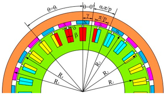 Figure 1. Configuration of the the direct drive permanent magnet motor (DDPMSM).
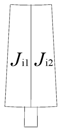 Figure 2. Current density distribution of double-layer winding in the slot.
Figure 1 shows the geometric representation of the model used in studying the slot opening on the air-gap magnetic field. The geometrical parameters include the radius of the slot bottom , the radius of the slot opening , the outer radius of the stator , the inner radius of the rotor surface , and the inner radius of the rotor yoke , where . is the initial position of the two-dimensional (2D) polar coordinates. is the slot width, is the slot opening width, and N denotes the number of slots. Then, the center position of the slot-opening can be expressed as follows:
To facilitate the calculation, the solution domain of the field problem of the DDPMM was divided into four types of subdomains, namely, stator slot subdomains, the stator slot-opening subdomains, the air-gap subdomain, and the rotor permanent magnet subdomains. Then, the boundary condition of each subdomain and the interface conditions between subdomains were applied. These boundary and interface conditions can be used to create the relationships between the coefficients and the sources, such as permanent magnets and currents. After determining the Fourier coefficients of the expressions in each subdomain, the general expression of the field distribution in each subdomain was obtained.
Since there was current distribution in the stator slot subdomains without magnetization, the Poisson equation on the stator slot subdomains is expressed as follows:
Based on the current density in the stator slot subdomains, the partial differential equation of the vector magnetic position can be expressed as
where the boundary conditions are
In the stator slot-opening subdomains, there was no current distribution and magnetization. Therefore, the Laplace equation is expressed as follows:
Then, the partial differential equation of the vector magnetic position in the stator slots-opening subdomains can be expressed as
where the boundary conditions are
As there is neither current density distribution nor magnetization in the air-gap subdomain, the Laplace equation is
Thus, the partial differential equation of the vector magnetic position in the air-gap subdomain can be expressed as
where the boundary conditions are
In the rotor permanent magnet subdomains, there is no current distribution, but the magnetization exists. Therefore, the Poisson equation in the rotor permanent magnet subdomains is expressed as follows:
Subsequently, the partial differential equation of the vector magnetic position in the rotor permanent magnet subdomains can be expressed as
where the boundary conditions are
In summary, the general formula for solving each DDPMM subdomain is expressed as follows:
According to the winding configuration in Figure 2, the current density in the slot for the double-layer winding can be expressed as
where , , and .
To clarify the general solution of the equations of the different subdomains, two functions are defined as follows:
Then, according to the boundary and interface conditions, the vector magnetic potential of the air-gap subdomain can be given by the method of separation of variables.
where n is the harmonic orders and , , , and are the Fourier coefficients to be determined by the boundary conditions.
The problem is solved in 2D polar coordinates. The adopted assumptions indicate that the magnetic vector potential only has one component along the z-direction and only depends on r and θ coordinates. Thus, the radial and tangential components of magnetic density in the air-gap subdomain can be expressed as follows:
Substituting (18) into (19), the following equations can be obtained:
It can be seen from Equations (20) and (21) that the slot opening width affects the coefficient of the magnetic field distribution in the air-gap subdomain. Therefore, the sinusoidal property of the air-gap magnetic density waveform is determined by the slot opening width, which affects the motor performance.
3. FEA Analysis
To verify the effect of the slot opening width on the air-gap magnetic field distribution, the finite element models with open and closed slots were established for the DDPMM with 24 poles and 27 slots, to compare the air-gap magnetic field distributions, as shown in Figure 3. In contrast to Figure 3a, the slot opening width of the DDPMM in Figure 3b was 2 mm. The main parameters of the DDPMM are reported in Table 1.
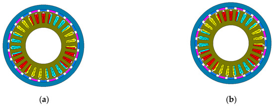
Figure 3.
Finite element models of DDPMM: (a) DDPMM with open slots; (b) DDPMM with closed slots.

Table 1.
Main parameters of the DDPMM.
Figure 4 depicts the air-gap flux density waveforms of the DDPMM with open and closed slots. Regions A, B, and C show the air-gap flux density of the three motor units. The waveform in Region A is identical to those in Regions B and C. Positions 1–4 represent the different positions of the slot opening relative to the permanent magnet. The waveform in Region A indicates that the slot opening affects the distribution of the air-gap magnetic field and the effect degree varies at different positions.
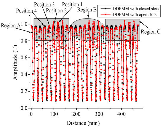
Figure 4.
Air-gap flux density waveforms of the DDPMM with open and closed slots.
The slot opening in the stator had symmetry with respect to the position of the permanent magnet. Thus, the centerline of the permanent magnet was considered the criterion in classifying the air-gap magnetic field distribution into four situations, as shown in Figure 4, Figure 5, Figure 6, Figure 7 and Figure 8.
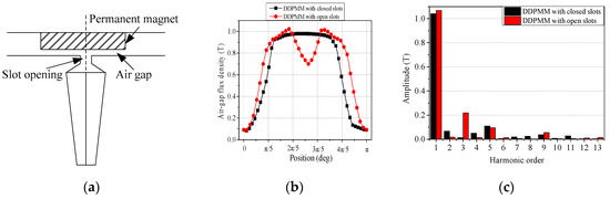
Figure 5.
Magnetic field analysis at position 1: (a) position 1; (b) air-gap flux density waveforms; (c) harmonics of air-gap flux density.
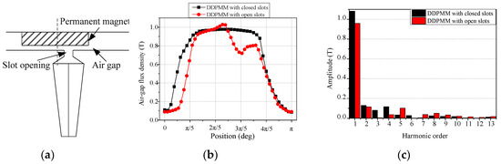
Figure 6.
Magnetic field analysis at position 2: (a) position 2; (b) air-gap flux density waveforms; (c) harmonics of air-gap flux density.
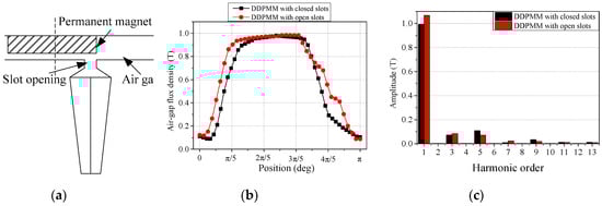
Figure 7.
Magnetic field analysis at position 3: (a) position 3; (b) air-gap flux density waveforms; (c) harmonics of air-gap flux density.
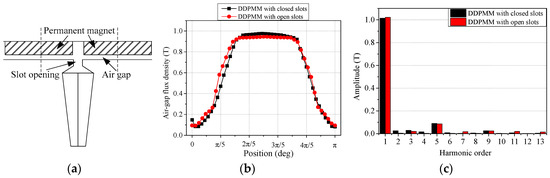
Figure 8.
Magnetic field analysis at position 4: (a) position 4; (b) air-gap flux density waveforms; (c) harmonics of air-gap flux density.
Figure 4, Figure 5, Figure 6, Figure 7 and Figure 8 show the analysis of the air-gap magnetic field distributions and their harmonics at different positions. Figure 4, Figure 5, Figure 6, Figure 7 and Figure 8 indicate that the air-gap flux density waveforms of the DDPMM with open slots differed from those of the DDPMM with closed slots in terms of the amplitude and the distribution of air-gap flux density. In addition, the Fourier analysis in Figure 4, Figure 5, Figure 6, Figure 7 and Figure 8 shows that the fundamental component and the total harmonic distortions (THDs) of air-gap flux density in the DDPMM with open slots differed from those of the DDPMM with closed slots. Therefore, the slot opening width dose affects the air-gap magnetic field. Furthermore, the comparisons in Figure 4, Figure 5, Figure 6, Figure 7 and Figure 8 depict the effect degree of slot opening width on the air-gap magnetic field that varies with the different positions.
Table 2 and Table 3 compare the fundamental amplitude and the THD of the air-gap flux density in the DDPMMs with closed and open slots. The effect proportion in Table 2 and Table 3 refers to the ratio of the difference between the value in the DDPMM with a closed slot to that with an open slot. The air-gap flux density was affected by the slot opening width.
Table 2.
Fundamental amplitudes of air-gap flux density at different positions.
Table 3.
Total harmonics distortions (THDs) of air-gap flux density at different positions.
4. Air-Gap Flux Density Analysis
In this section, several finite element DDPMM models with eight poles and nine slots, 16 poles and 18 slots, and 24 poles and 27 slots are established based on the structure of the unit motor with eight poles and nine slots. Subsequently, the air-gap magnetic field of the three models was investigated at these four positions.
4.1. Air-Gap Flux Density Analysis of DDPMM with Eight Poles and Nine Slots
As shown in Figure 9, the air-gap magnetic field of the DDPMM with eight poles and nine slots was analyzed at different positions. The Fourier analysis in the figure shows that the harmonic amplitudes in the air-gap magnetic field changed with the increase in slot opening width. Particularly, the values of the third and fifth harmonics increased with the slot opening width.
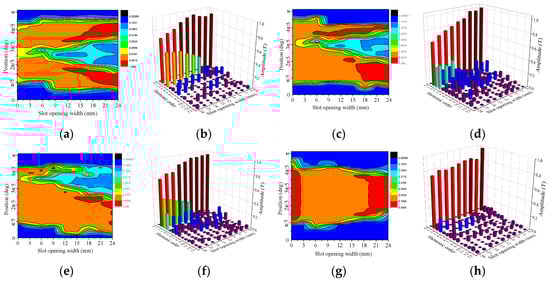
Figure 9.
Air-gap magnetic field analysis of the DDPMM with eight poles and nine slots at different positions: (a) magnetic field distribution at position 1; (b) harmonics at position 1; (c) magnetic field distribution at position 2; (d) harmonics at position 2; (e) magnetic field distribution at position 3; (f) harmonics at position 3; (g) magnetic field distribution at position 4; (h) harmonics at position 4.
Figure 9a describes the air-gap magnetic field distribution at different slot opening widths at position 1. When the slot opening width was less than 9 mm, the air-gap magnetic field at the corresponding position of the slot opening was concave. The width and depth of the concave also increased with the slot opening width. When the slot opening width was greater than 9 mm, the magnetic field on both sides of the slot opening was agglomerated and the value of the magnetic field was significantly higher than that in other areas. Figure 9b shows the Fourier analysis of the air-gap magnetic field at different slot opening widths at position 1. When the slot opening width was less than 9 mm, the harmonics of air-gap flux density included not only odd harmonics, but also fewer even harmonics. However, all harmonic amplitudes were small.
Figure 9c,d reveals the air-gap magnetic field distribution and its fast Fourier transform (FFT) analysis at different slot opening widths at position 2, respectively. The air-gap magnetic field distribution in Figure 9c shows the same trend as that in Figure 9a. However, the positions that correspond to the magnetic field concaved and agglomerated are different from that in Figure 9a. The comparison between Figure 9a,c indicates that the third harmonic content in Figure 9c was reduced and the second harmonic content was increased. Similar conclusions can also be obtained from Figure 9e,f.
The variations of air-gap magnetic field distribution and its FFT analysis with different slot opening widths at position 2 were analyzed, as shown in Figure 9g,h. As opposed to the air-gap magnetic field distributions at positions 1–3, the air-gap magnetic field distribution at position 4 was less affected by the slot opening width. As can be seen from Figure 9h, the fifth harmonic was the main harmonic component. In addition, when the slot opening width was 0 mm, the total harmonic content was low. When the slot opening width was greater than 21 mm, the third harmonic content was significantly increased.
4.2. Air-Gap Flux Density Analysis of DDPMM with 16 Poles and 18 Slots
Figure 10 shows the analysis of the air-gap magnetic field distribution of DDPMM with 16 poles and 18 slots and its harmonic components at different slot opening widths. In comparison with Figure 9, the agglomerated magnetic field region in Figure 10 is wider, the harmonic content in the air-gap magnetic field is lesser, and its waveform is relatively closer to the sinusoidal. In addition, the harmonics in Figure 10 are mainly composed of harmonics below the seventh harmonic.
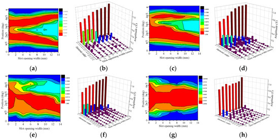
Figure 10.
Air-gap magnetic field analysis of the DDPMM with 16 poles and 18 slots at different positions: (a) magnetic field distribution at position 1; (b) harmonics at position 1; (c) magnetic field distribution at position 2; (d) harmonics at position 2; (e) magnetic field distribution at position 3; (f) harmonics at position 3; (g) magnetic field distribution at position 4; (h) harmonics at position 4.
Figure 10a,b shows the magnetic field distribution at position 1. No serious fluctuation occurred in the concave section of the magnetic field, and the fundamental amplitude was increased compared with that in Figure 9. Furthermore, the harmonics mainly included the fifth harmonics when the slot opening width was less than 8 mm, and the main harmonic was the third harmonic when the width of the slot opening was greater than 8 mm. However, the amplitude of each harmonic was smaller than that of the harmonic in Figure 9 at the same conditions.
The magnetic field distributions in Figure 10c,f show the same trend as that in Figure 9 in terms of the width and depth of the concaved magnetic field. However, the fundamental value increased, the amplitudes of the second and third harmonics decreased, and the total harmonics were suppressed. Figure 10g,h show that the magnetic field evidently changed when the slot opening width was between 2 mm and 6 mm. This was mainly affected by the fifth harmonic.
4.3. Air-Gap Flux Density Analysis of DDPMM with 24 Poles and 27 Slots
Figure 11 shows the air-gap magnetic field distribution of the DDPMM with 24 poles and 27 slots and its harmonic components at different slot opening widths. The harmonic contents and their air-gap magnetic field amplitudes were reduced. The air-gap magnetic field harmonics in position 1 mainly included the third harmonic. The value of the fifth harmonic was very small and the amplitudes of the other harmonics were almost zero. Figure 11d shows that the second, third, and fifth harmonics are the main factors that affected the magnetic field distribution. In position 3, the air-gap flux density was only affected by the second harmonic. The harmonics in Figure 11h mainly consisted of the third, fifth, and seventh harmonics.
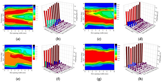
Figure 11.
Air-gap magnetic field analysis of the DDPMM with 24 poles and 27 slots at different positions: (a) magnetic field distribution at position 1; (b) harmonics at position 1; (c) magnetic field distribution at position 2; (d) harmonics at position 2; (e) magnetic field distribution at position 3; (f) harmonics at position 3; (g) magnetic field distribution at position 4; (h) harmonics at position 4.
5. Conclusions
Herein, the effect of slot opening width on the air-gap magnetic field was investigated. In addition to the introduction of the exact analytical model, the analytical general solution of the air-gap magnetic field was obtained, thereby showing that the slot opening can affect the air-gap magnetic field distribution. Subsequently, the air-gap magnetic fields of DDPMM with closed and open slots were compared. Moreover, the finite element models of motors composed of unit motor were established to analyze the effect of slot opening width on the air-gap magnetic field based on different slot opening widths. The FEM results reveal that the air-gap magnetic field is affected by the slot opening width. Some characteristics are summarized as follows.
- (1)
- The slot opening width affects the air-gap magnetic field distribution. The width and depth of the concaved magnetic field rise, and the harmonics of the air-gap flux density change with the increase in the slot opening width.
- (2)
- The effect of slot opening width on the air-gap magnetic field varies with different positions. As the slot opening position deviates from the center of the permanent magnet, the position of the concaved magnetic field shifts, and the main harmonic in the air-gap magnetic field gradually changes from the third harmonic to the second harmonic. Moreover, when the slot opening corresponds to the gap of two permanent magnets, the air-gap magnetic field distribution is less affected by the slot opening width.
- (3)
- The slot opening width has different effects on the air-gap magnetic field distribution in the motors composed by different numbers of unit motor. With the increase in the number of unit motor, the fundamental amplitude of the air-gap magnetic field in the motor increases, the total harmonic contents decrease, and the value of each harmonic also reduces.
Therefore, different slot openings have certain effects on the air-gap magnetic field. This study provides a reference for optimizing the air-gap magnetic field distribution of a DDPMM.
Author Contributions
Data curation, Y.H. (Yihua Hu); Formal analysis, S.C., C.G., M.G. and J.S.; Funding acquisition, Y.H. (Yaofei Han); Investigation, Y.H. (Yihua Hu); Methodology, Y.H. (Yaofei Han), S.C., M.G. and J.S.; Resources, Y.H. (Yaofei Han); Software, Y.H. (Yaofei Han), S.C., C.G. and M.G.; Writing—original draft, Y.H. (Yaofei Han) and S.C.
Funding
This research is supported by the open fund of Henan Intelligent Power Transmission and Conversation Engineering Research Center, Henan University of Urban Construction (2019SPBH08).
Conflicts of Interest
The authors declare no conflict of interest.
References
- Salminen, P.; Pyrhönen, J.; Libert, F. Torque ripple of permanent magnet machines with concentrated windings. In Proceedings of the International Symposium on Electromagnetic Fields in Mechatronics, Electrical and Electronic Engineering, Baiona, Spain, 15–17 September 2005. [Google Scholar]
- Zhu, Z.Q.; Xia, Z.P.; Wu, L.J. Analytical modeling and finite element computation of radial vibration force in fractional-slot permanent magnet brushless machines. IEEE Trans. Ind. Appl. 2010, 46, 1908–1918. [Google Scholar] [CrossRef]
- Zhu, Z.Q.; Howe, D.; Mitchell, J.K. Magnetic field analysis and inductances of brushless DC machines with surface-mounted magnets and non-overlapping stator windings. IEEE Trans. Magn. 1995, 31, 2115–2118. [Google Scholar] [CrossRef]
- Bellara, A.; Amara, Y.; Barakat, G. Two-dimensional exact analytical solution of armature reaction field in slotted surface mounted PM radial flux synchronous machines. IEEE Trans. Magn. 2009, 45, 4534–4538. [Google Scholar] [CrossRef]
- Iwasaki, S.; Deodhar, R.P.; Liu, Y. Influence of PWM on the proximity loss in permanent-magnet brushless AC machines. IEEE Trans. Ind. Appl. 2009, 45, 1359–1367. [Google Scholar] [CrossRef]
- Amara, Y.; Reghem, P.; Barakat, G. Analytical prediction of eddy current loss in armature windings of permanent magnet brushless AC machines. IEEE Trans. Magn. 2010, 46, 3481–3484. [Google Scholar] [CrossRef]
- Zhu, Z.Q.; Howe, D. Instantaneous magnetic field distribution in brushless permanent magnet DC motors, part I: Open-circuit field. IEEE Trans. Magn. 1993, 29, 124–135. [Google Scholar] [CrossRef]
- Zhu, Z.Q.; Howe, D. Instantaneous magnetic field distribution in brushless magnet DC motors, part III: Effect of stator slotting. IEEE Trans. Magn. 1993, 29, 143–151. [Google Scholar] [CrossRef]
- Souissi, A.; Abdennadher, I.; Masmoudi, A. Analytical Prediction of the No-Load Operation Features of Tubular-Linear Permanent Magnet Synchronous Machines. IEEE Trans. Magn. 2016, 52, 1–7. [Google Scholar] [CrossRef]
- Shin, K.H.; Park, H.I.; Cho, H.W. Analytical Calculation and Experimental Verification of Cogging Torque and Optimal Point in Permanent Magnet Synchronous Motors. IEEE Trans. Magn. 2017, 53, 1–4. [Google Scholar] [CrossRef]
- Dalal, A.; Kumar, P. Analytical Model for Permanent Magnet Motor with Slotting Effect, Armature Reaction, and Ferromagnetic Material Property. IEEE Trans. Magn. 2015, 51, 1–10. [Google Scholar] [CrossRef]
- Ding, Y.; Zhang, Y.J. Semi-analytical method research for non-load air gap field of surface alnico permanent magnet brushless motor. Electr. Mach. Control Appl. 2007, 3, 7–10. [Google Scholar]
- Zheng, C.Y.; Zhang, Y.J. Semi–analytical approach with vector magnetic potential for permanent-magnet air-gap field of surface mounted stator slot. Small Spec. Electr. Mach. 2010, 4, 24–26. [Google Scholar]
- Bramerdorfer, G.; Winkler, S.M.; Kommenda, M. Using FE calculations and data-based system identification techniques to model the nonlinear behavior of PMSMs. IEEE Trans. Ind. Electron. 2014, 61, 6454–6462. [Google Scholar] [CrossRef]
- Bai, J.; Zheng, P.; Tong, C. Characteristic analysis and verification of magnetic field modulated brushless double rotor machine. IEEE Trans. Ind. Electron. 2015, 62, 4023–4033. [Google Scholar] [CrossRef]
© 2019 by the authors. Licensee MDPI, Basel, Switzerland. This article is an open access article distributed under the terms and conditions of the Creative Commons Attribution (CC BY) license (http://creativecommons.org/licenses/by/4.0/).