1. Introduction
Carbon fiber-reinforced plastic (CFRP) is an attractive material candidate for weight reduction due to its high strength-to-weight ratio compared to metals. It is especially promising for the automotive industry since toughening environmental regulations and high fuel prices have demanded reduced carbon emissions and improved fuel efficiency [
1,
2,
3]. However, the lack of reliable and productive means for joining dissimilar materials has limited the use of CFRPs. Only a handful of methods for joining CFRP and other metals have been used such as chemical binders and a few mechanical means. The toxic chemicals comprising the binders pose serious environmental and health problems and the relatively long processing time accompanied by the need for temporary fixtures has made chemical joining process inefficient [
1]. The mechanical joining methods usually require careful alignment of the holes between the parts to be joined, and this poses a challenge for automation. In addition, the added weight of rivets, bolts, and screws increases the overall weight, which defeats the purpose of using lightweight CFRPs [
1]. Furthermore, at the end of the lifecycle of the products, the presence of both chemical binders and mechanical joints makes recycling costly, which can be a significant environmental issue in the near future. Therefore, there is a high demand for new joining technologies such as fusion welding. Fusion welding is nearly impossible for thermoset CFRPs since they burn under the intense heat of the welding process. Thermoplastic CFRPs, on the other hand, allow fusion welding and thus can be a good alternative for increasing the production efficiency [
4,
5,
6,
7]. Thermoplastic CFRP has been known to exhibit lower strength and lower heat resistance compared to its thermoset counterpart, but the recent advancement of thermoplastics has removed most of its weaknesses [
8].
Many prior studies have investigated the application of laser fusion welding between CFRP and metals [
4,
5,
6,
7]. Katayama et al. [
4,
5] showed that tight bonding between the polymer matrix and the metal surface could be achieved by generating bubbles in the molten zone of the CFRP matrix. Expanding pressure caused by the bubbles pushes the molten polymer flow onto the metal surface structures. Surface pre-treatments prior to the joining process have been demonstrated as an effective method to enhance dissimilar joining strength [
6,
7]. Lambiase and Ko investigated the feasibility of mechanical clinching for CFRP–aluminum joining and found that a high jointing strength of 2.5 kN can be achieved. Zhang et al. [
9] showed that the pre-treatment of aluminum with the laser Surfi-Sculpt process could improve the shear strength of dissimilar joints to a large extent and discussed the bonding and the failure mechanisms of the dissimilar joints. The same group also investigated the effect of surface grafting on the laser joining strength of CFRP and aluminum alloy [
10]. The results showed that the shear strength of the joint could be enhanced up to 600% using optimized UV grafting parameters, and new bonds including Al–C and Al–O–C could be the reason for such high joining strength improvement [
11].
In this study, we investigate the influence of pre-inscribed laser surface patterning, via nanosecond pulse laser, on the laser fusion-bonding strength of carbon fiber-reinforced polyetheretherketone (CFR-PEEK) and zinc-coated steel (so-called galvannealed steel). The materials are chosen since PEEK is considered as one of the most promising candidates for replacing PA6 or PA66 for a thermoplastic polymer matrix for carbon fiber composites due to its high thermal resistance, mechanical strength, and moisture resistance, and zinc-coated steel has been increasingly adopted in the automotive industry for improved corrosion resistance [
8]. Optimization of the processing parameters, including laser power, focal position, pitch, number of passes, and clamping pressure was done prior to introducing the pre-inscribed laser patterns. Then, the laser power, a number of passes, and pitch were varied to find the optimized patterning parameters using the secondary nanosecond laser. The tensile shear strength test reveals that the strength of the joint with laser surface structuring increased by up to 100% compared to that of the samples without surface structures. We also present SEM images of the patterned surface and the cross-section of the joint to investigate the nature of the increased bonding strength and the optimized parameters.
2. Materials and Methods
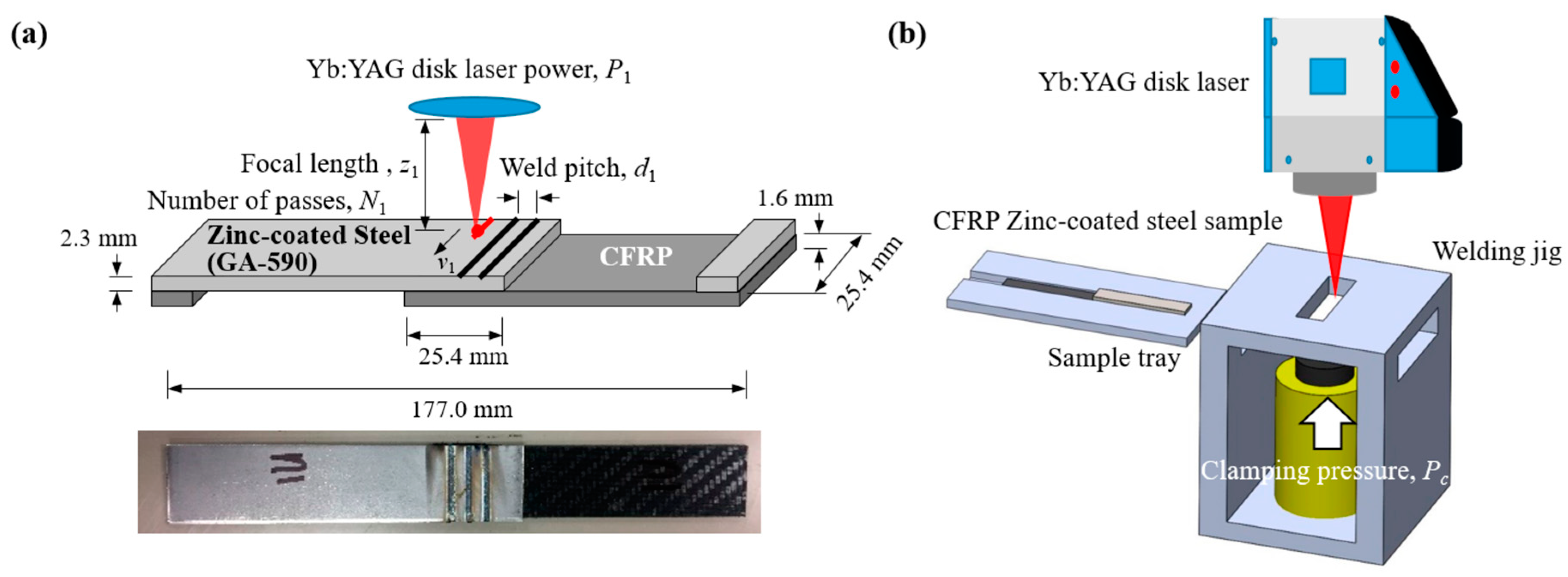
The schematic of the laser fusion bonding (or welding) of CFRP and zinc-coated steel is shown in
Figure 1. Commercially available 1.6-mm thick tri-axial (0°/−60°/+60°) non-crimp fabric with tricot counter-stitch and a polyetheretherketone (PEEK) matrix was used for the CFRP sample (manufacturer: SAERTEX
® GmbH & Co., Saerbeck, Germany, KG), while 2.6-mm thick commercially available zinc-coated DP 590 steel sheets with 43.8 g/m
2 of zinc coating applied on each side were used as the joining counterpart. The roughness was measured using a surface profiler (Mitutoyo SJ-400), and the values for the CFRP and the steel sheets were Ra = 0.29 μm, Ry = 2.53 μm and Ra = 1.21 μm, Ry = 8.83 μm, respectively. A continuous mode Yb:YAG disk laser HLD 4002 (Trumpf, Ditzingen, Germany) was used for the laser welding process. The laser beam was delivered through an optical fiber with a diameter of 200 μm and optic system PFO33 (Trumpf, Ditzingen, Germany). The delivered beam was collimated (length of collimation: 150 mm) and focused (focal length: 450 mm), which resulted in a focal diameter of 0.6 mm with a beam quality (beam parameter product) of 8.5 mm∙rad. The welding was done on a custom-made jig (shown in the bottom of
Figure 1) with a clamping pressure of
Pc. No shielding gas was used in this study.
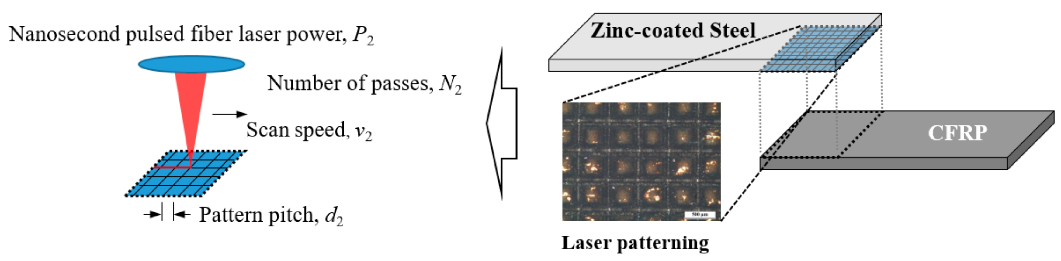
The rectangular laser pattern on the zinc-coated steel surface was produced using a nanosecond pulsed fiber laser (IPG YLPN-1-20 × 120-100) operating at 1064 nm. The laser was set to produce ~120-ns pulses at a frequency of 50 kHz. The average output power was varied between 8 and 45 W. The beam shape was near-Gaussian, and at focus, the beam spot size of full width 1/e2 maximum (FW1/e2M) was approximately 125 μm in diameter. A two-mirrored galvanometric scanner and an X-Y-Z motion stage were used to control the position and the motion of the laser beam spots for the production of the rectangular grid pattern shown in
Figure 2.
The tensile shear tests, to quantify the joining strength of the laser-welded samples, were performed using a Shimadzu AG-300KNX Universal Testing Machine (maximum load capacity of 30 tons). The dimensions of the specimen and the test procedure conform to the ASTM D 5868 standard, and the schematic of the tensile test specimen is shown in
Figure 1. Three samples for each condition were prepared, and the results were averaged. The crosshead speed was 5 mm/min for all the tensile shear tests.
3. Results and Discussion
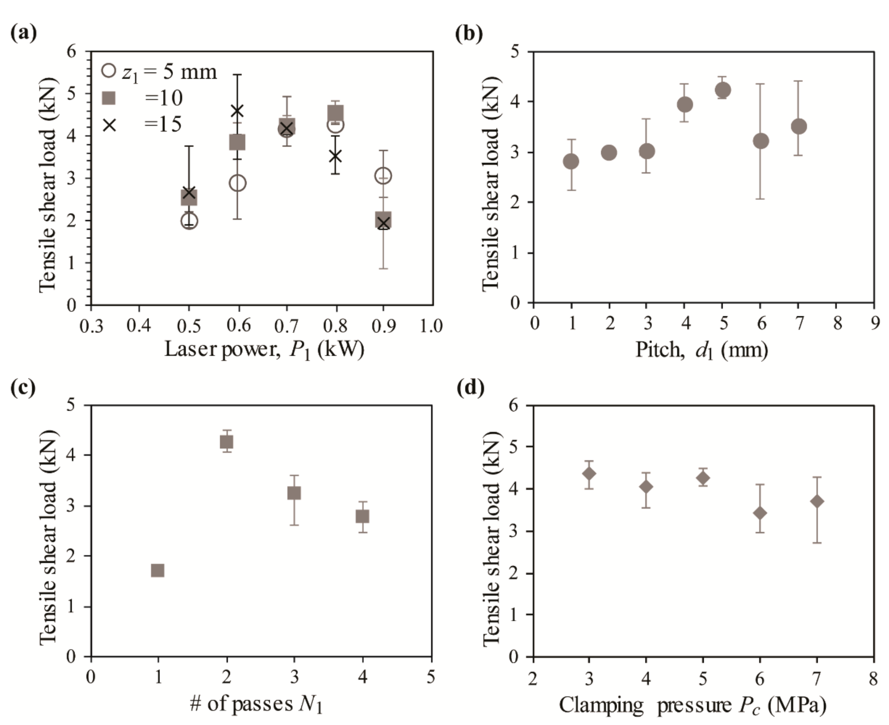
To find the optimal processing conditions for the laser fusion bonding of CFRP and zinc-coated steel, a parametric study was performed by varying the welding parameters, and the tensile shear load test results of each case are shown in
Figure 3.
Figure 3a shows the tensile shear load with respect to (w.r.t.) the laser power
P1 at different focal positions,
z1 = 5, 10, 15 mm. The figure shows that for the samples used in this study, the optimal laser power is approximately 0.7 kW, resulting in a tensile shear load of 4.26 kN at
z1 = 10 mm. The optimal laser power was chosen since the results show high tensile shear load test results for all the focal lengths with a minimum amount of errors. The figure also shows that the optimal
z1 value is 10 mm, which results in a relatively high tensile shear load with relatively small variations. Next, the influence of the pitch
d1 on the tensile shear load is investigated, and the results are presented in
Figure 3b. The figure shows that the maximum tensile shear load of 4.26 kN is obtained for the weld pitch of
d1 = 5 mm. The results show that as
d1 is increased from 1 to 5 mm, the tensile shear load is increased. However, when
d1 is increased above 5 mm, the results become unreliable, although the maximum tensile load is maintained at approximately 4.2 kN. The number of passes
N1 in each weld line is found to be an important parameter, and the tensile load test results w.r.t.
N1 are shown in
Figure 3c. The results in the figure show that the tensile shear load of
N1 = 2 is significantly higher than that of
N1 = 1, since a single path is not enough to fully fuse the two materials at the optimized laser power of 0.7 kW. However, as
N1 is increased beyond 2, the tensile shear strength is decreased, which is suspected to be the result of the increased thermal damage on the polymer matrix of the CFRP in the interfacial area. Finally, tensile shear load tests, for the samples using different clamping pressures denoted by
Pc are conducted, and the results are shown in
Figure 3d. The figure shows that the tensile shear load is maintained at approximately 4 kN up to
Pc = 5 MPa. However, the reliability is reduced as it is further increased.
The parametric study shows that for this study, the optimized laser processing parameters in laser fusion welding of CFRP and zinc-coated steel are: P1 = 0.7 kW, z1 = 10 mm, d1 = 3 mm, N1 = 2, and Pc = 5 MPa. We use these parameters for investigating the effect of pre-inscribed rectangular patterns on the joining strength of the two dissimilar materials.
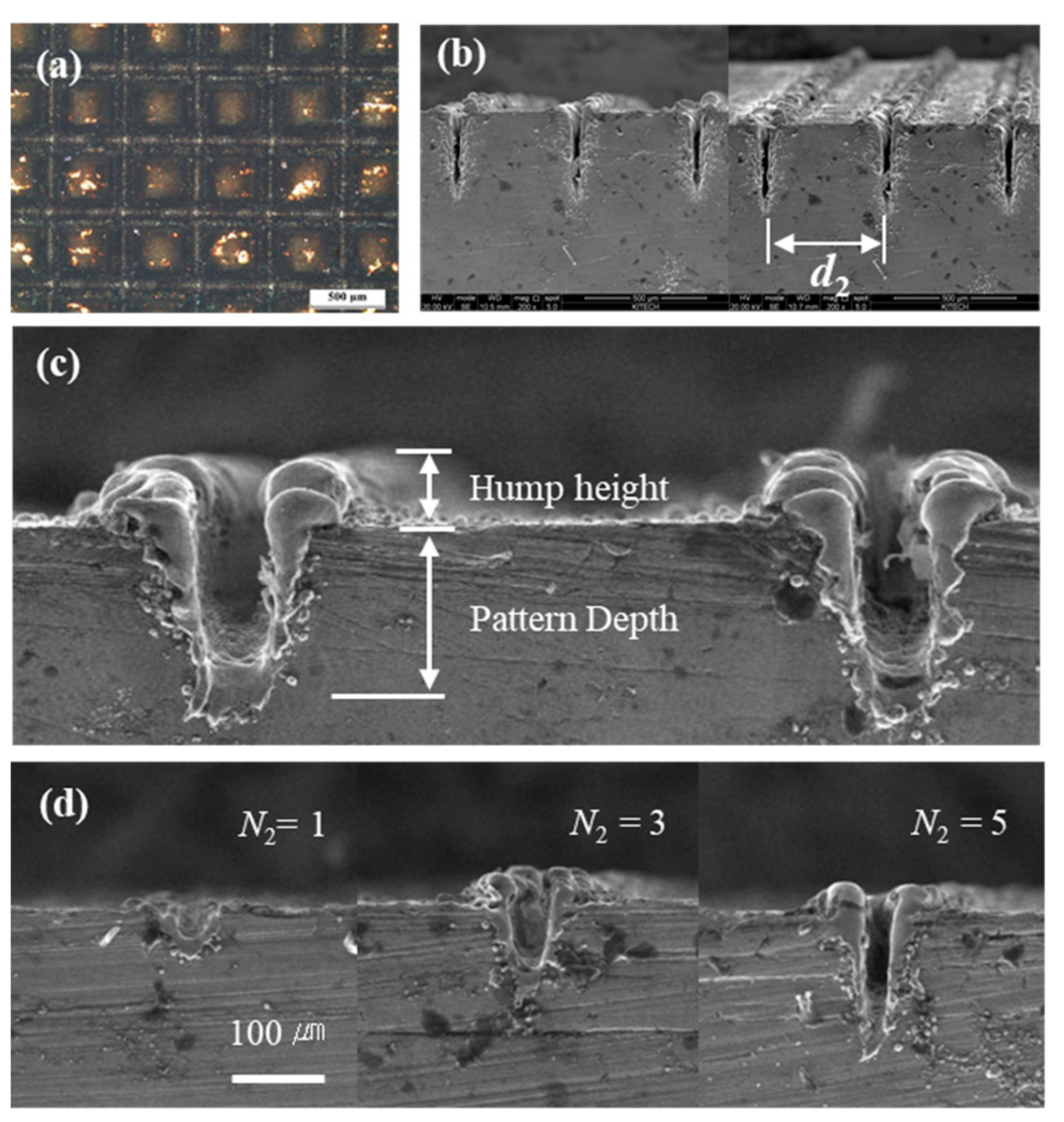
In an effort to increase the bonding strength of the fusion welded joint between CFRP and the zinc-coated steel sheets, the surface of the steel, which overlaps with the CFRP sample, is pre-inscribed with a rectangular pattern using a nanosecond pulsed laser, as shown in
Figure 4a. The laser pattern chosen for this study is a rectangular pattern with a varying line pitch represented by
d2, as shown in
Figure 4b. The magnified image in
Figure 4c shows that when the surface of the steel is patterned using the nanosecond laser, the recondensed debris from the process forms a hump along the laser path.
Figure 4d shows the SEM image of the laser patters as
N2 is increased from 1 to 5. It shows that although the depth of the pattern consistently increases as
N2 is increased, the width of the pattern is not consistent, yet decreases due to the increased amount of recondensed debris after
N2 = 3.
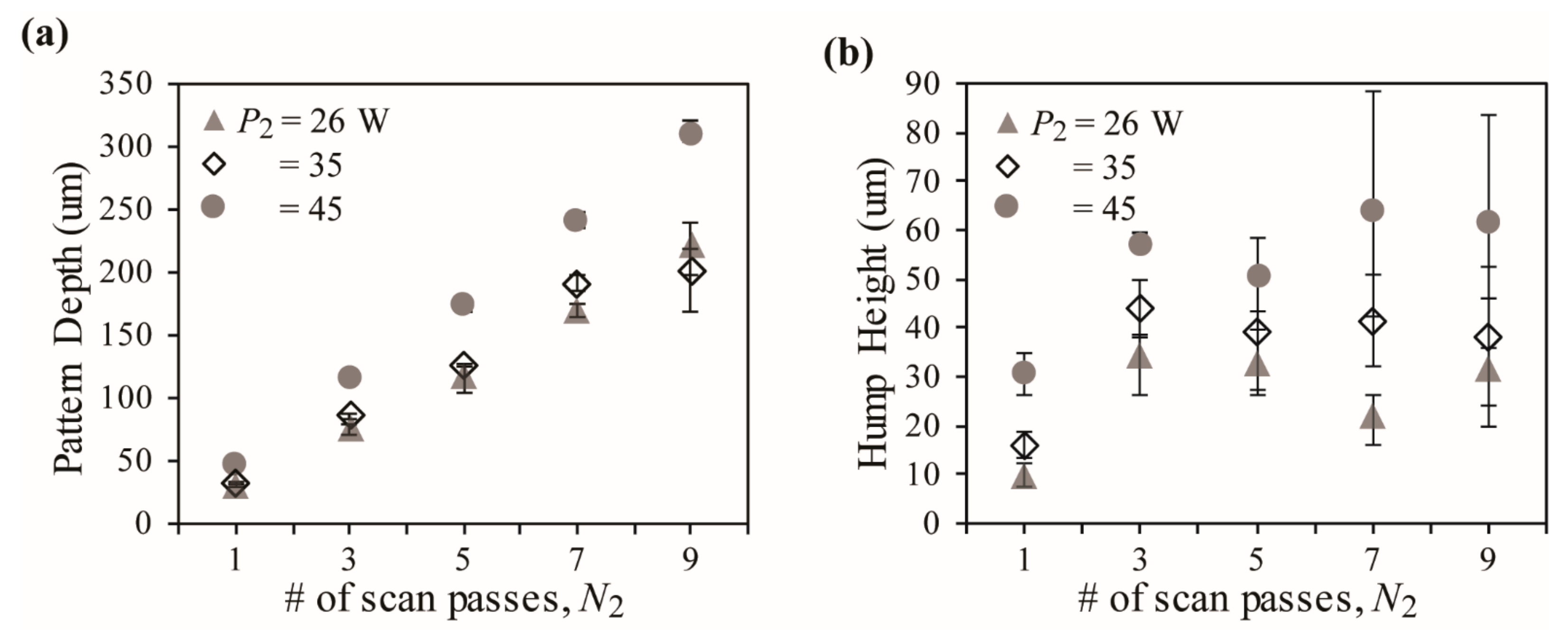
The pattern depth and the hump height are measured w.r.t. the number of scan passes
N2, and the results are shown in
Figure 5a,b. As expected, the pattern depth consistently increases with the increasing
N2 value, since more material is removed as the number of scans is increased. The height of the hump was found to generally increase with increasing
P2 values, but the trend is inconclusive for increasing
N2 values due to large variations. Formation of the hump is undesirable, since it hampers tight contact between the materials to be welded, leading to increased gas encapsulation and lower weld qualities.
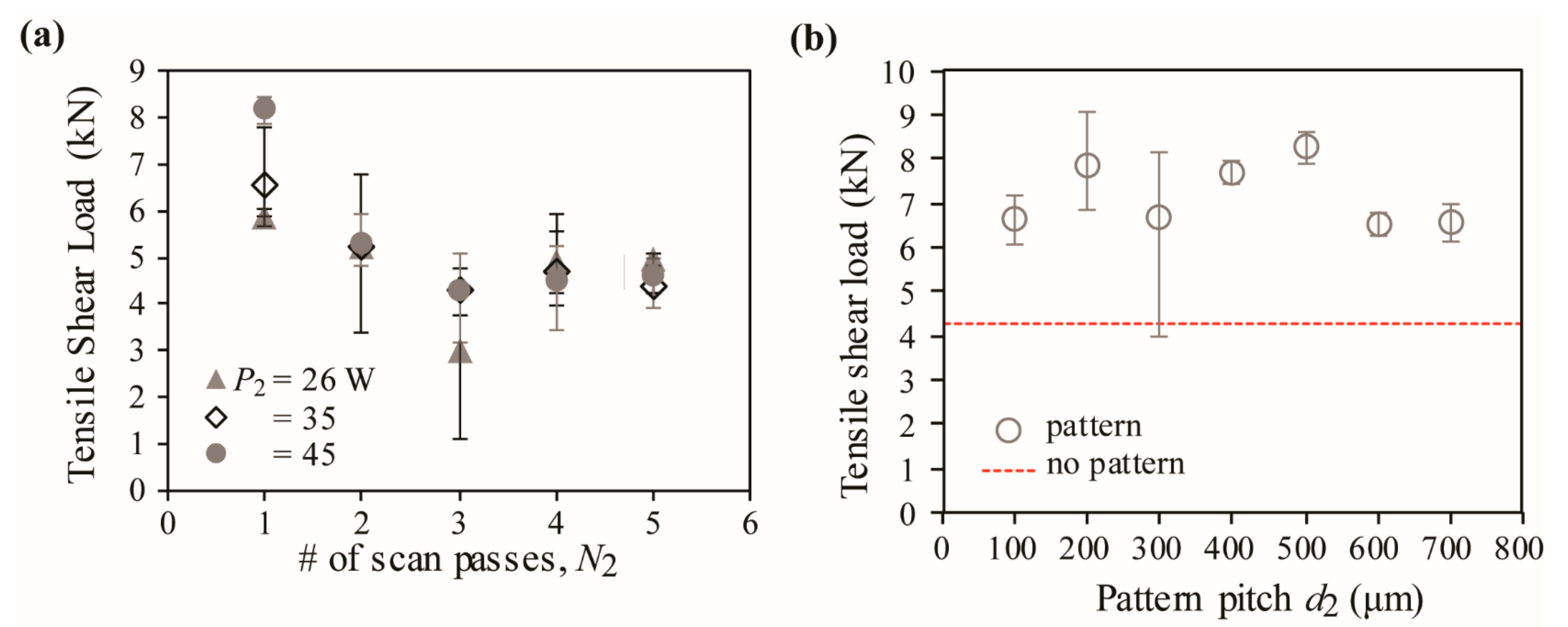
Tensile shear load test results for the laser fusion-bonded CFRP and pre-inscribed rectangular surface patterned zinc-coated steel is shown in
Figure 6a for varying
N2 values and in
Figure 6b for varying
d2 values. The results clearly show that the tensile shear load is at maximum for
N2 = 1 and decreases as
N2 is increased to 3, and then is approximately maintained at a constant value. The figure also shows that the power of the nanosecond laser used to pattern the zinc-coated steel does not influence the tensile shear strength of the joint. Such results indicate that the pattern depth and the hump height resulting from the pattering laser does not correlate with the tensile shear strength. For example, the presence of the pattern indeed increases the tensile shear strength of the fusion-welded CFRP and zinc-coated steel. However, when the pattern depth becomes more than 75 μm, it causes an adverse effect.
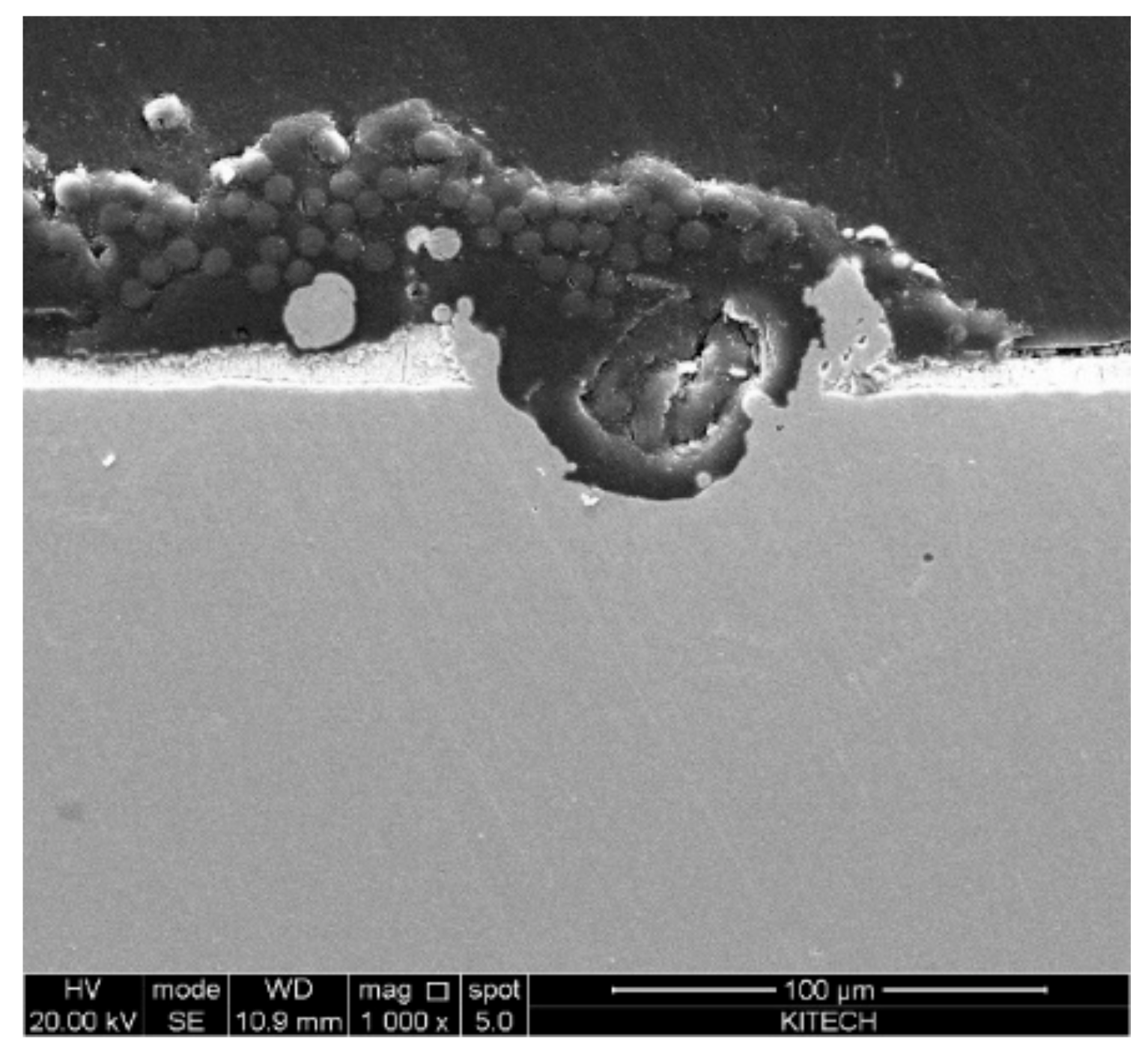
Figure 7 shows the SEM image of the fractured cross-section of the welded joint after the tensile shear test. The figure shows that CFRP residues are present within the laser-patterned grooves. This shows that the improved anchoring effect due to the laser pattern causes a partial cohesive fracture resulting in improved joining strength compared to that of the pure interfacial fractures observed in the joint with no patterns. The tensile shear load test results for the laser fusion-bonded CFRP and surface patterned zinc-coated steel are shown in
Figure 6b for the varying pattern pitch
d2 when
N2 = 1. The results show that for all the pattern pitch sizes, the tensile shear load is increased compared to the samples with no surface pattern. Considering the uncertainty of the results, we conclude that the optimal pattern pitch is near 500 μm, which results in an approximately 100% increase in tensile shear load compared to that of no surface patterning, although the correlation between tensile shear load and pitch is marginal.
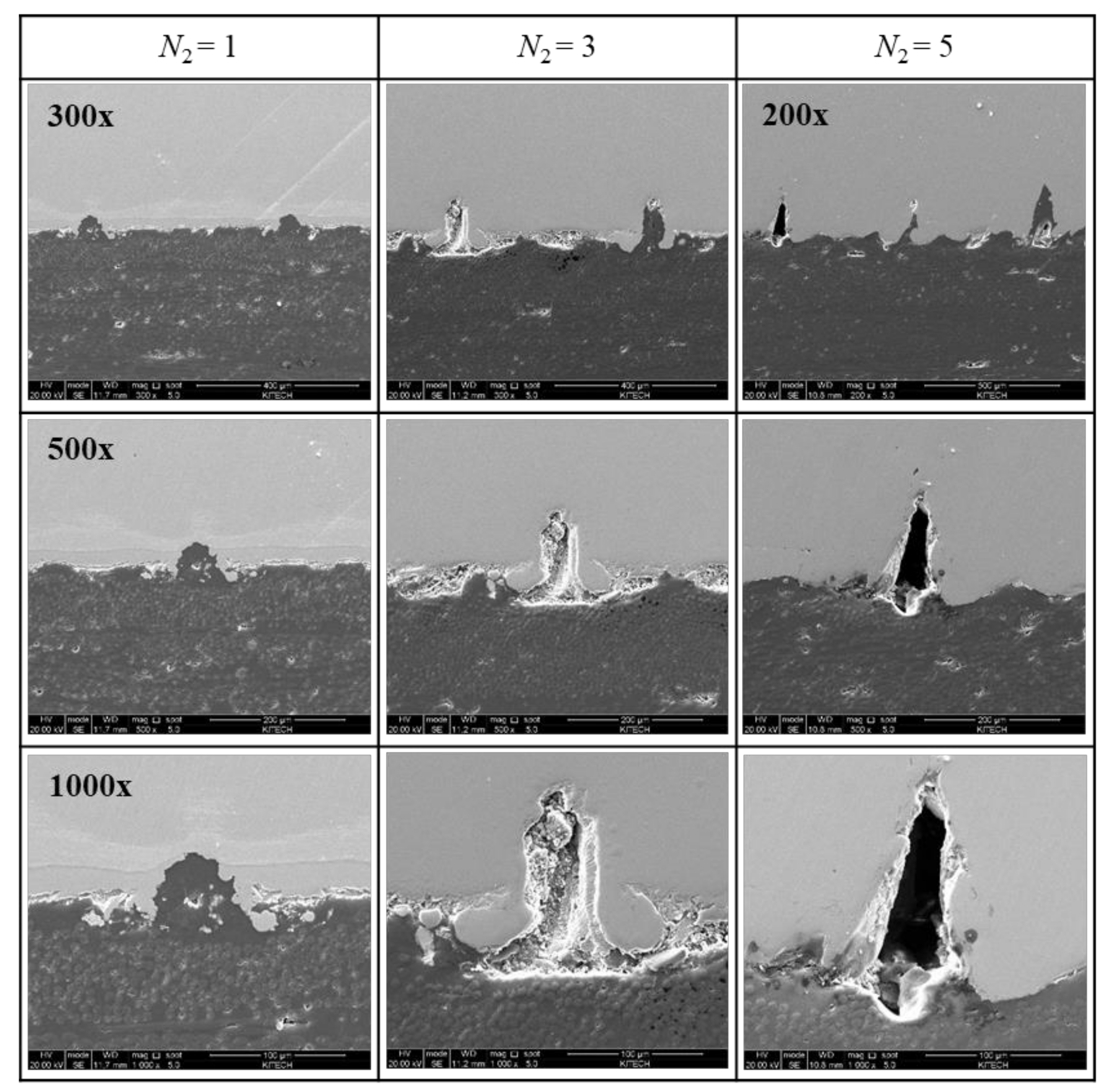
The cross-section of the laser fusion-welded CFRP and zinc-coated steel was investigated using SEM imaging to understand the nature of the increased tensile shear strength up to
N2 = 3 and decreased tensile shear strength at
N2 = 5. The SEM images in
Figure 8 show that at
N2 = 1, the PEEK matrix has seeped into the shallow grooves formed by the pre-inscription during the laser fusion process forming a tight bond between the two dissimilar material, thereby increasing the bonding strength. However, as
N2 is increased to 3, the images show that the recondensed particles become trapped inside of the pre-inscription, hindering the PEEK matrix from flooding the grooves. As
N2 is increased further to 5, the images show that some grooves formed by the pre-inscription have become too deep for the PEEK matrix to seep into the cavities during the welding process, leaving large vacancies in which gases may be trapped. Such results show that although all the joints with rectangular patterns result in a higher tensile shear load compared to that of non-patterned joints, there exist optimal parameters that maximize the bonding strength between the CFRP and zinc-coated steel.
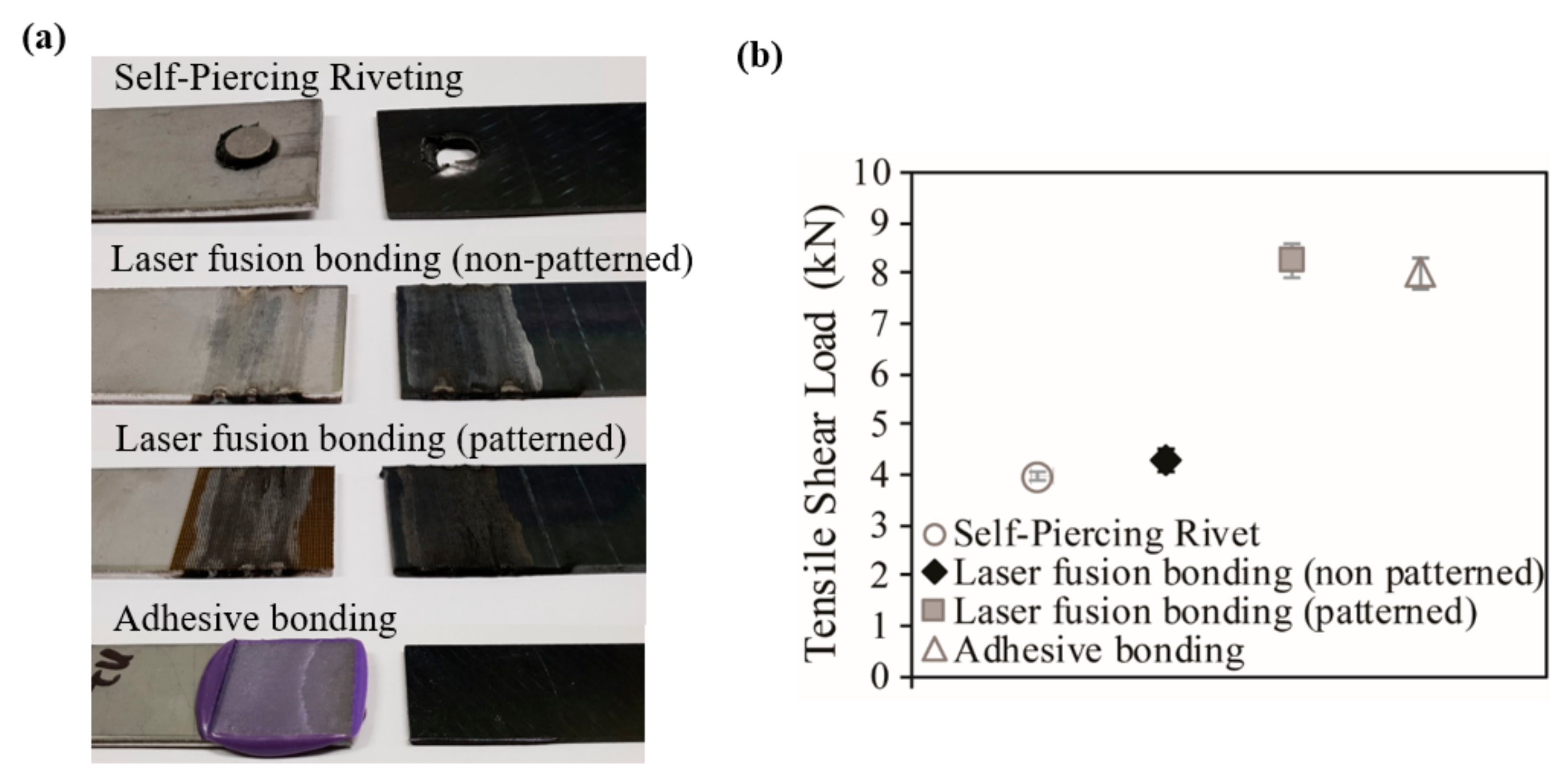
Figure 9 shows the comparison of the tensile shear load test results for the CFRP and zinc-coated steel joint using four different kinds of methods: self-piercing rivet, laser fusion bonding with and without pre-inscribed patterning, and adhesive bonding. The results show that for this study, joints formed using non-patterned laser fusion bonding exhibit comparable tensile shear loads to self-piercing rivets with approximately 4 kN, while joints formed using patterned laser fusion bonding exhibit comparable tensile shear loads to adhesive bonding with approximately 8 kN. Therefore, it can be concluded that the pre-inscribed rectangular patterns on the zinc-coated steel sheets significantly improve (up to 100%) the tensile shear load of joints between CFRP and zinc-coated steel, and this is a result of an improved fusion between the two dissimilar materials due to the presence of pre-inscribed grooves.

