Influence of Gravity on Molten Pool Behavior and Analysis of Microstructure on Various Welding Positions in Pulsed Gas Metal Arc Welding

Abstract
:1. Introduction
2. Experimental Procedure
2.1. Materials and Experiment Conditions
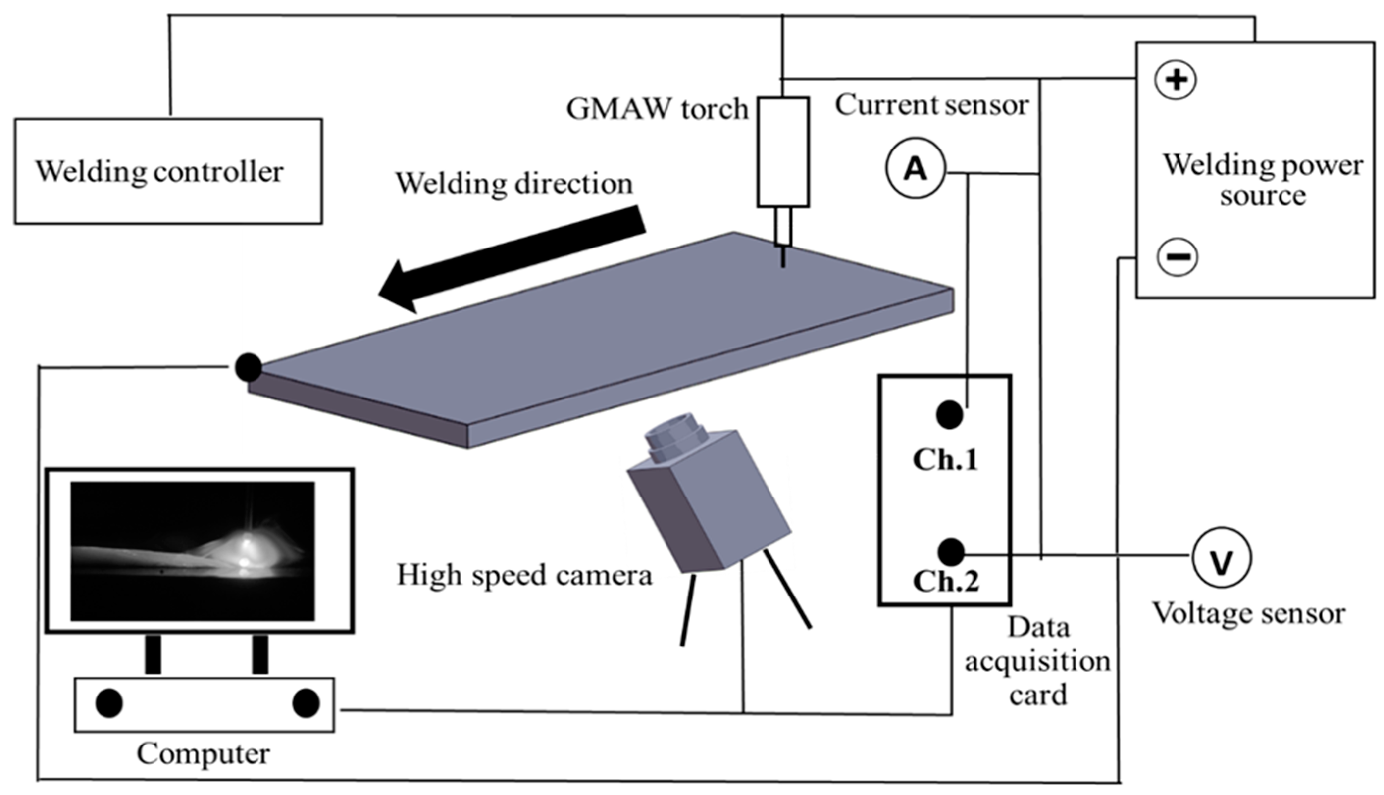
2.2. Welding Equipment
2.3. Preparation for Metallographic Examination
3. Results and Discussion
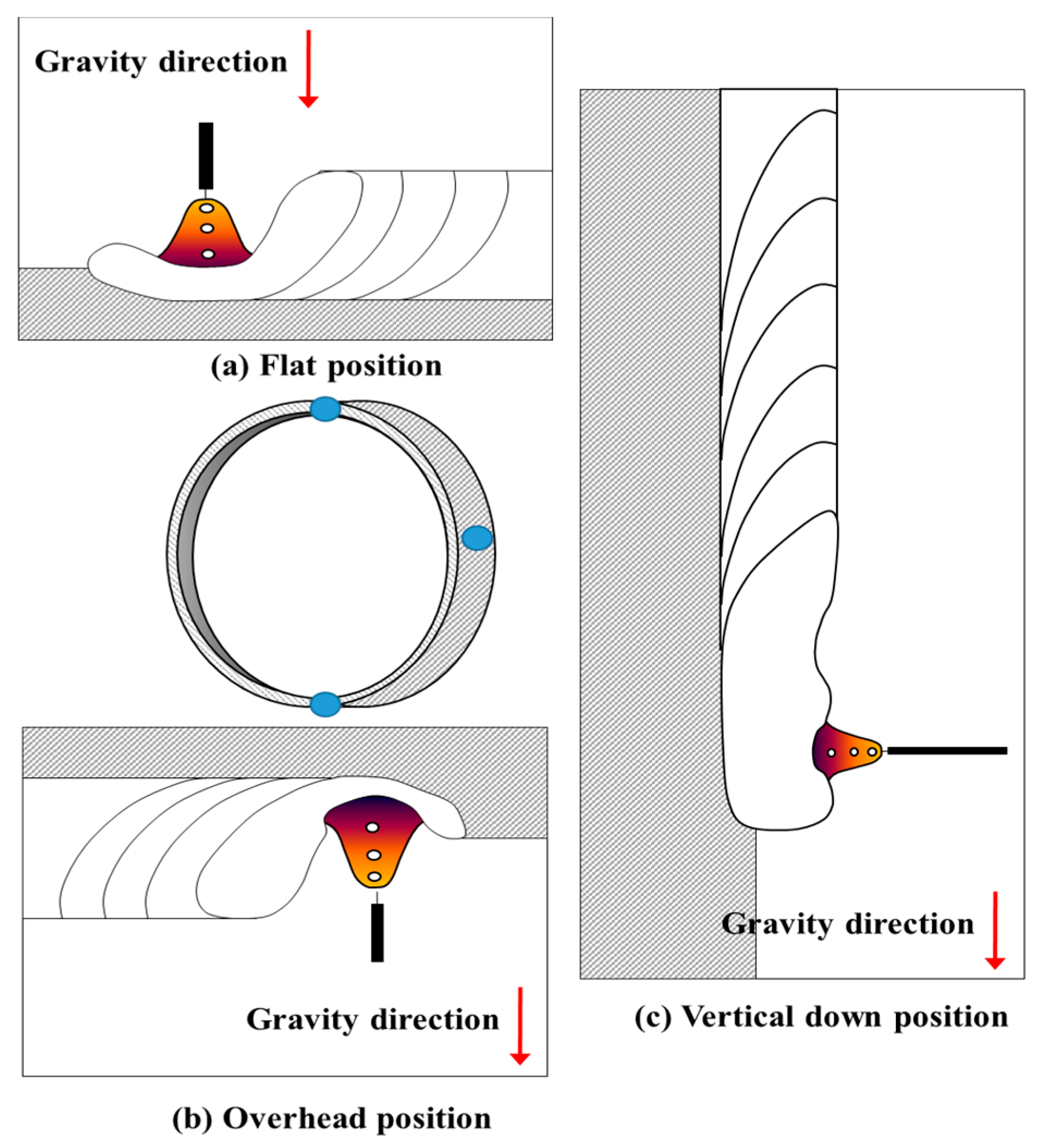
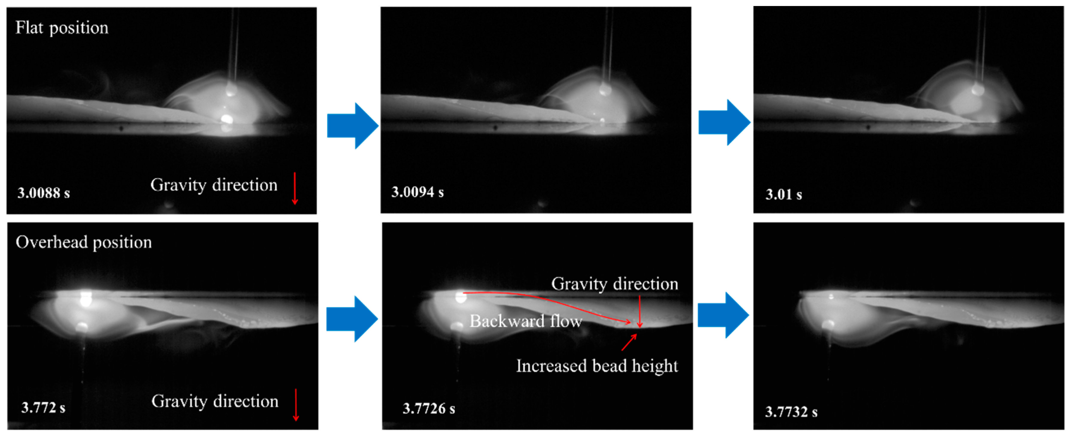
3.1. Flat Position
3.2. Overhead Position
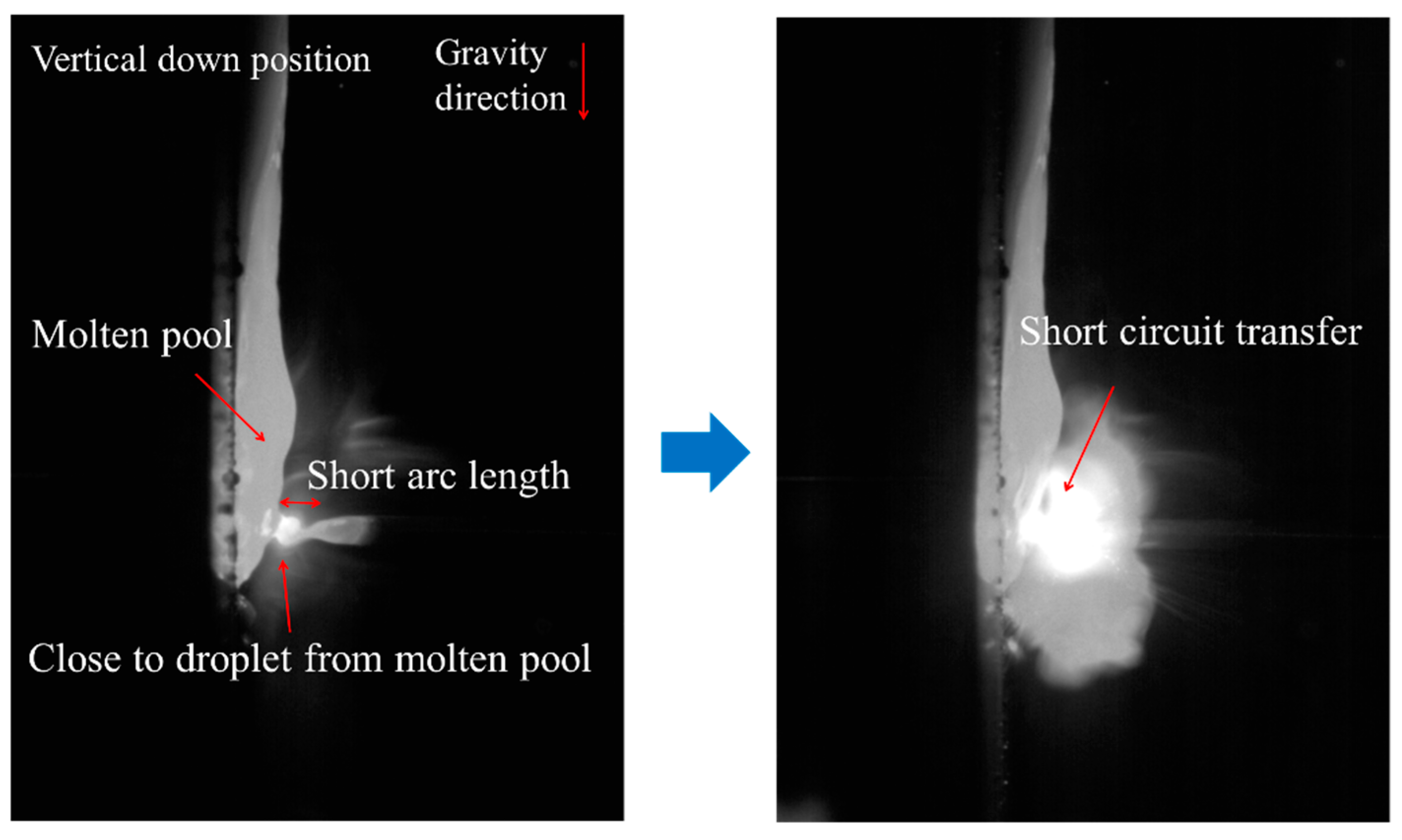
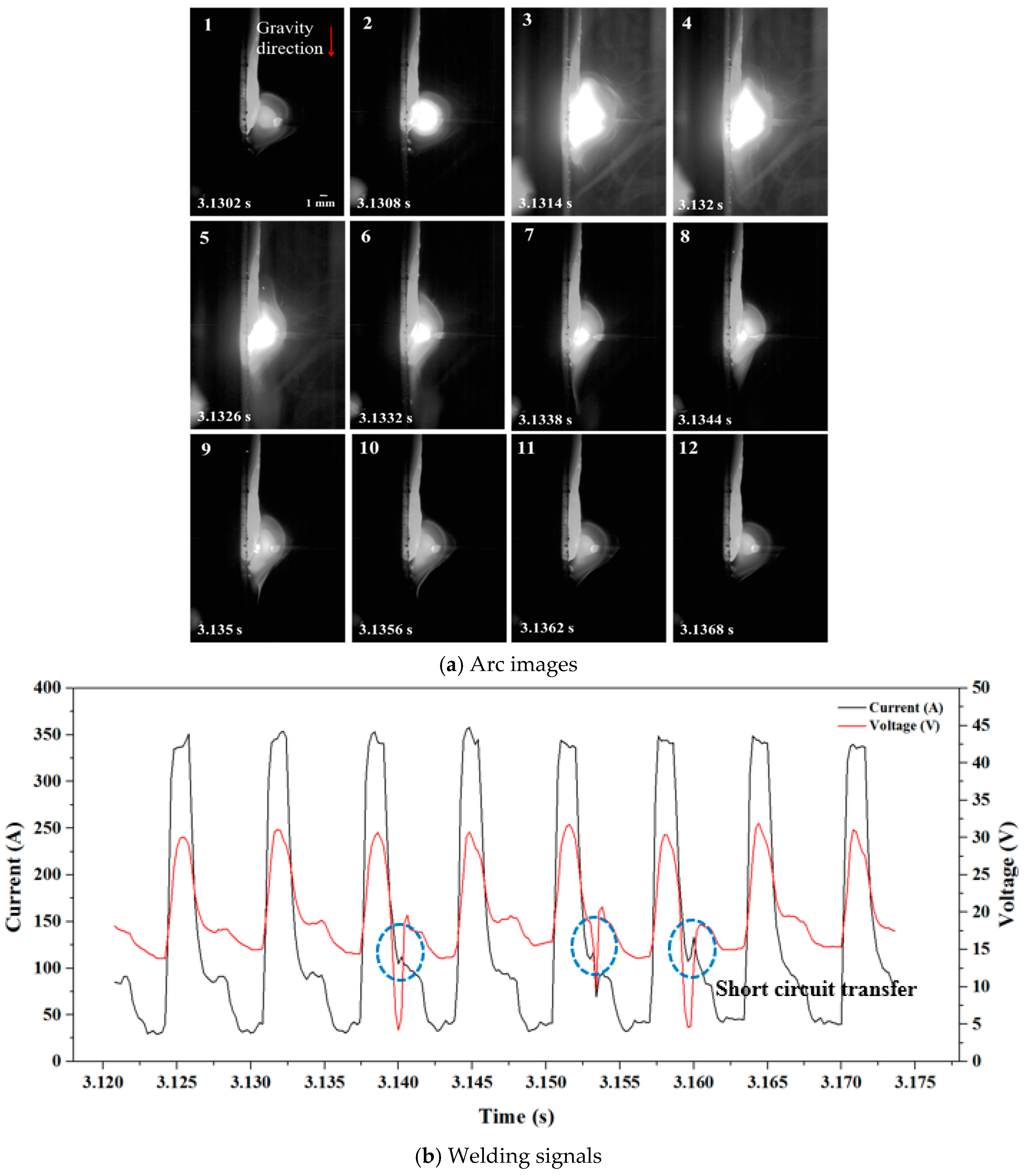
3.3. Vertical down Position
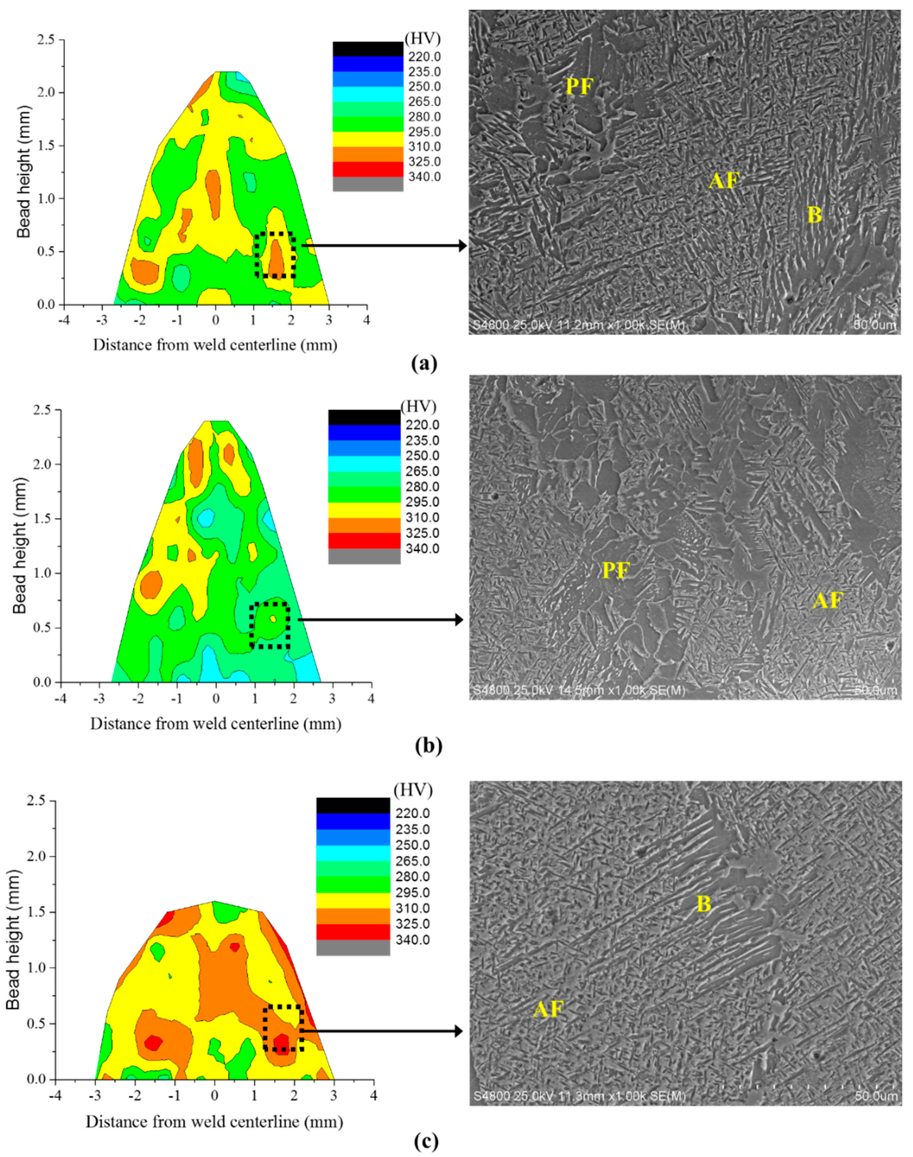
3.4. Analysis of Microstructure and Hardness Character
4. Conclusion
Author Contributions
Funding
Conflicts of Interest
References
- Kumar, R.; Dilthey, U.; Dwivedi, D.K.; Ghosh, P.K. Thin sheet welding of Al 6082 alloy by AC pulse-GMA and AC wave pulse-GMA welding. Mater. Des. 2009, 30, 306–313. [Google Scholar] [CrossRef]
- Kim, R.H.; Choi, G.D.; Kim, C.H.; Cho, D.W.; Na, S.J. Arc characteristics in pulse-GMA welding with acute groove angles. Weld. J. 2012, 91, 101–104. [Google Scholar]
- Zhang, Y.M.; Liguo, E.; Kovacevic, R. Active metal transfer control by monitoring excited droplet oscillation. Weld. J. 1998, 77, 388s–395s. [Google Scholar]
- Wu, C.S.; Chen, M.A.; Li, S.K. Analysis of excited droplet oscillation and detachment in active control of metal transfer. Comput. Mater. Sci. 2004, 31, 147–154. [Google Scholar] [CrossRef]
- Kou, S.; Sun, D.K. Fluid flow and weld penetration in stationary arc welds. Met. Trans. A 1985, 16, 203–213. [Google Scholar] [CrossRef]
- Guokai, Z.; Chuansong, W.; Xinfeng, L. Single vision system for simultaneous observation of keyhole and weld pool in plasma arc welding. J. Mater. Process. Technol. 2015, 215, 75–78. [Google Scholar]
- Saeed, G.; Zhang, Y.M. Weld pool surface depth measurement using a calibrated camera and structured light. Meas. Sci. Technol. 2007, 18, 2570–2578. [Google Scholar] [CrossRef]
- Wu, C.S.; Zhong, L.M.; Gao, J.Q. Visualization of hump formation in high-speed gas metal arc welding. Meas. Sci. Technol. 2009, 20, 1–8. [Google Scholar] [CrossRef]
- Nagarajan, S.; Banerjee, P.; Chen, W.H. Control of the welding process using infrared sensors. IEEE Trans. Robot. Autom. 1992, 8, 86–93. [Google Scholar] [CrossRef]
- Carlson, N.M.; Johnson, J.A. Ultrasonic sensing of weld pool penetration. Weld. J. 1988, 67, 47. [Google Scholar] [CrossRef]
- Wang, X.W. Three-dimensional vision applications in GTAW process modeling and control. Int. J. Adv. Manuf. Technol. 2015, 80, 1601–1611. [Google Scholar] [CrossRef]
- Zhang, W.J.; Liu, Y.K.; Wang, X.; Zhang, Y.M. Characterization of three dimensional weld pool surface in GTAW. Weld. J. 2012, 91, 195–203. [Google Scholar]
- Liu, Y.K.; Zhang, W.J.; Zhang, Y.M. Dynamic neuro-fuzzy-based human intelligence modeling and control in GTAW. IEEE Trans. Autom. Sci. Eng. 2015, 12, 324–335. [Google Scholar] [CrossRef]
- Wang, G.; Tandon, K.N. The microstructural changes during welding of stainless steel under reduced gravity environment. Microgravity Sci. Technol. 1993, 6, 96–100. [Google Scholar]
- Aidun, D.K.; Martin, S.; Domey, J. The effect of gravity on the weld pool shape in stainless steel. In Centrifugal Materials Processing; Regel, L.L., Wilcox, W.R., Eds.; Plenum Press: New York, NY, USA, 1997; pp. 177–182. [Google Scholar]
- Kang, N.; Singh, J.; Kulkarni, A. Effects of gravitational orientation on the microstructural evolution of gas tungsten arc welds in an Al-4 wt% Cu alloy. J. Mater. Sci. 2003, 38, 3579–3589. [Google Scholar] [CrossRef]
- Kang, N.; Mahank, T.A.; Kulkarni, A.K.; Singh, J. Effects of gravitational orientation on surface deformation and weld pool geometry during gas tungsten arc welding. Mater. Manuf. Process. 2003, 18, 169–180. [Google Scholar] [CrossRef]
- Palani, P.K.; Murugan, N. Optimization of weld bead geometry for stainless steel claddings deposited by FCAW. J. Mater. Process. Technol. 2007, 190, 291–299. [Google Scholar] [CrossRef]
- Lee, C.S.; Chandel, R.S.; Seow, H.P. Effect of welding parameters on the size of heat affected zone of submerged arc welding. Mater. Manuf. Process. 2000, 15, 649–666. [Google Scholar] [CrossRef]
- Shen, S.; Qguocha, I.N.A.; Yannacopoulos, S. Effect of heat input on weld bead geometry of submerged arc welded ASTM A709 Grade 50 steel joints. J. Mater. Process. Technol. 2012, 212, 289–294. [Google Scholar] [CrossRef]
- Cho, D.W.; Park, J.H.; Moon, H.S. A study on molten pool behavior in the one pulse one drop GMAW process using computational fluid dynamics. J. Heat Mass Transf. 2019, 139, 848–859. [Google Scholar] [CrossRef]
- Xu, G.; Cao, Q.; Hu, Q.; Zhang, W.; Liu, P.; Du, B. Modelling of bead hump formation in high speed gas metal arc welding. Sci. Technol. Weld. Join. 2016, 8, 700–710. [Google Scholar] [CrossRef]
- Nguyen, T.C.; Weckman, D.C.; Johnson, D.A.; Kerr, H.W. The humping phenomenon during high speed gas metal arc welding. Sci. Technol. Weld. Join. 2005, 10, 447–459. [Google Scholar] [CrossRef]


| Parameter | Conditions |
|---|---|
| Shielding gas | 95% Ar+5% CO2, 20 L/min |
| Welding travel speed | 60 cm/min |
| Wire feed rate | 7 m/min |
| Contact tip to work distance | 15 mm |
| High-speed camera | Phantom m320s, frame rate 5000 Hz |
| Wire | Er70s-6, 1 mm |
| Band pass filter | 695 nm |
| Welding machine | TPS-2700 |
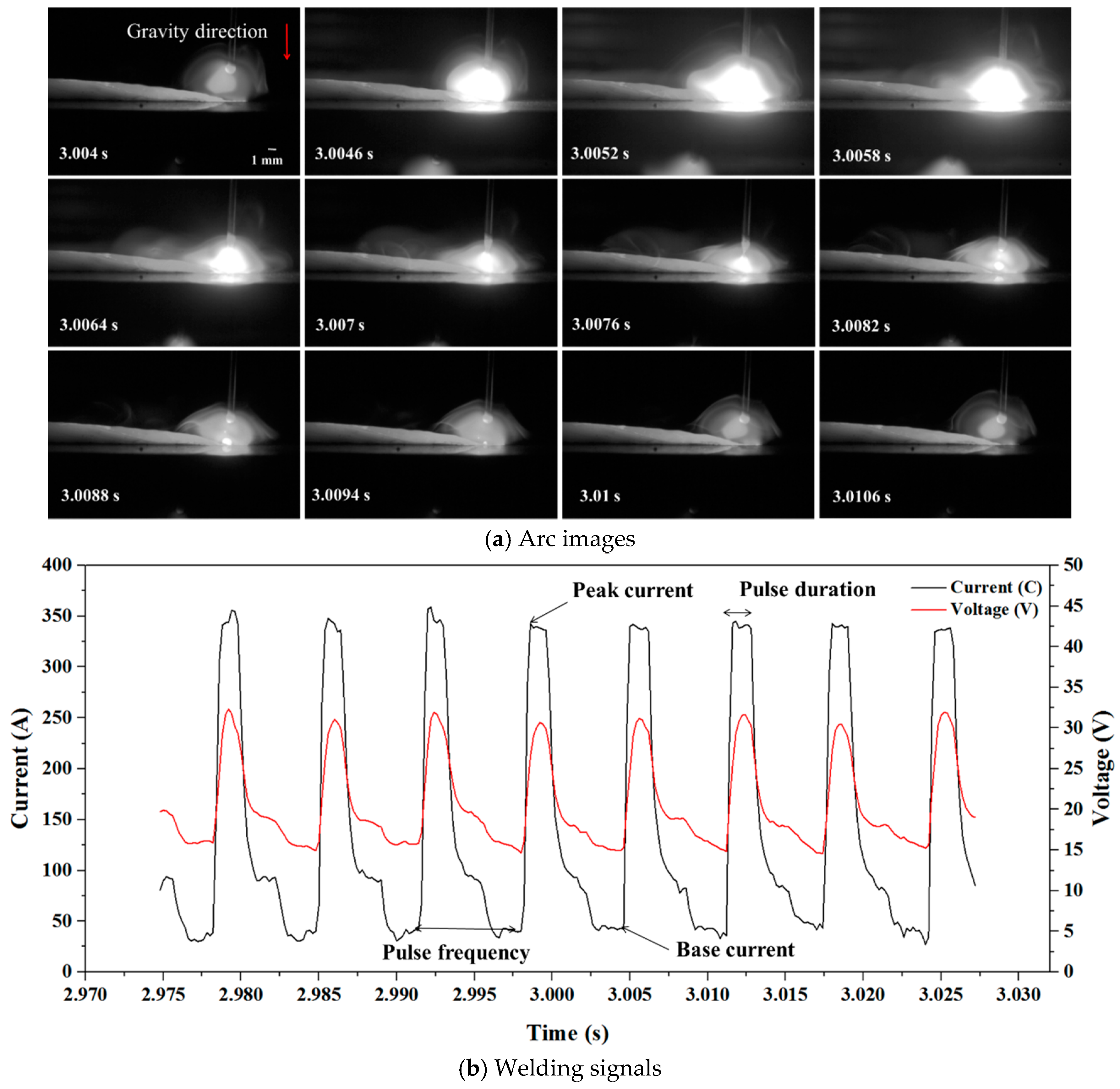
| Peak current | 345 A |
| Base current | 35 A |
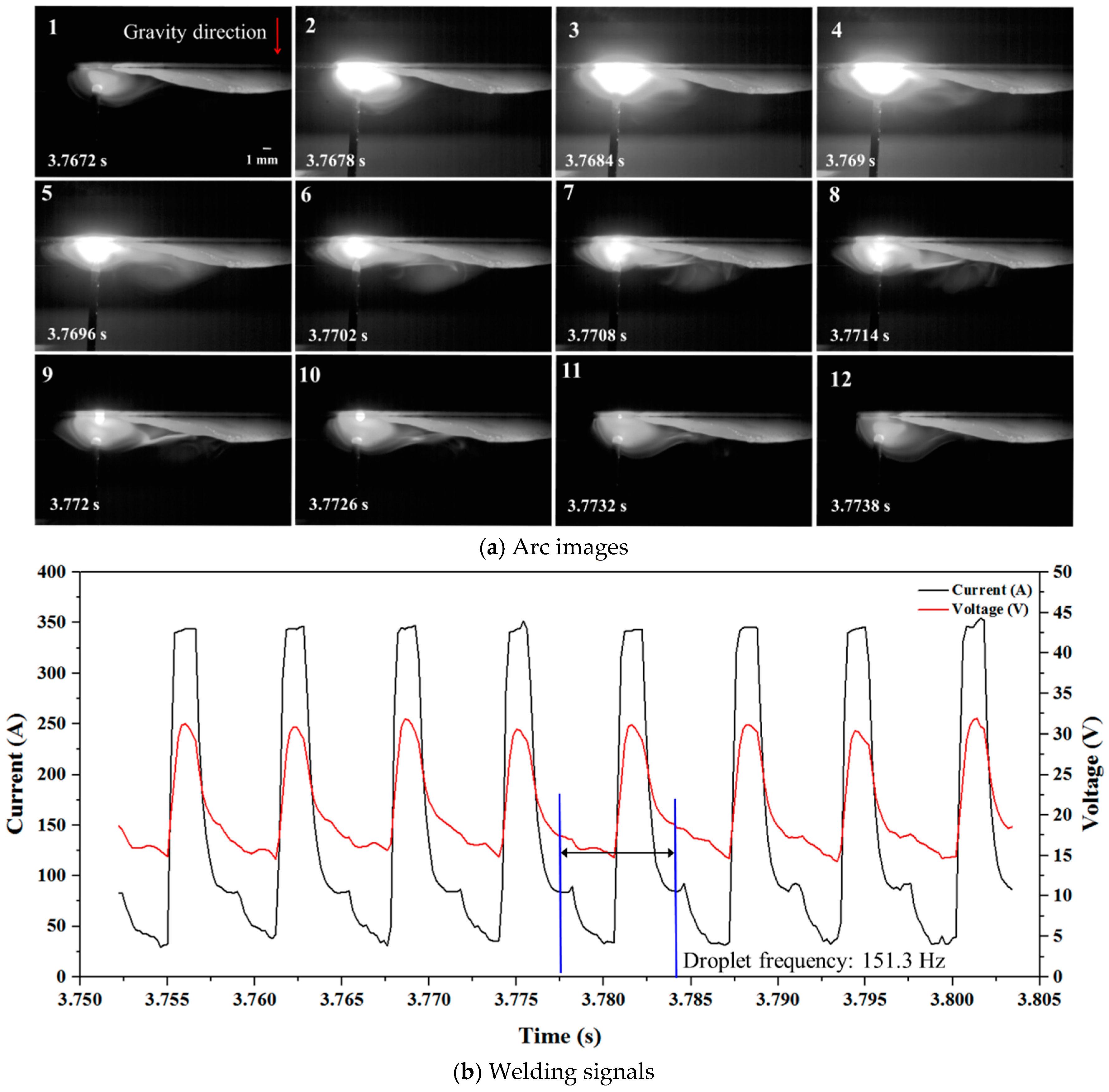
| Pulse frequency | 151.5 Hz |
| Pulse duration | 0.0012 s |
| Materials | C | Si | Mn | P | S | Al | Cu | Fe |
|---|---|---|---|---|---|---|---|---|
| SS400 | 0.16 | 0.20 | 0.6 | 0.01 | 0.008 | 0.05 | 0.02 | Bal. |
| ER70S-6 | 0.07–0.19 | 0.65–0.85 | 1–1.5 | <0.025 | 0.035 | 0.5–0.9 | >0.5 | Bal. |
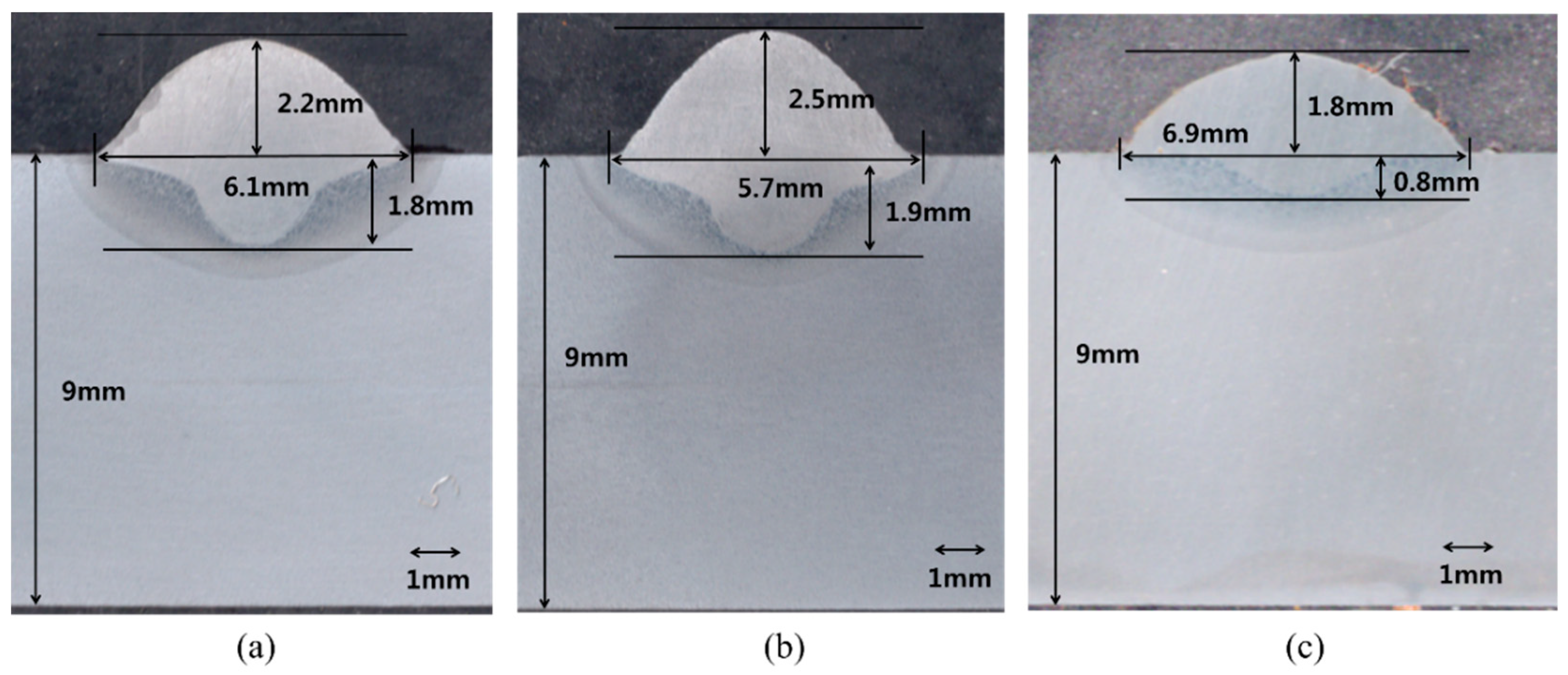
| Welding Position | Bead Width (mm) | Bead Height (mm) | Penetration (mm) |
|---|---|---|---|
| Flat | 6.1 | 2.2 | 1.8 |
| Overhead | 5.7 | 2.5 | 1.9 |
| Vertical down | 6.9 | 1.8 | 0.8 |
© 2019 by the authors. Licensee MDPI, Basel, Switzerland. This article is an open access article distributed under the terms and conditions of the Creative Commons Attribution (CC BY) license (http://creativecommons.org/licenses/by/4.0/).
Share and Cite
Park, J.-H.; Kim, S.-H.; Moon, H.-S.; Kim, M.-H. Influence of Gravity on Molten Pool Behavior and Analysis of Microstructure on Various Welding Positions in Pulsed Gas Metal Arc Welding. Appl. Sci. 2019, 9, 4626. https://doi.org/10.3390/app9214626
Park J-H, Kim S-H, Moon H-S, Kim M-H. Influence of Gravity on Molten Pool Behavior and Analysis of Microstructure on Various Welding Positions in Pulsed Gas Metal Arc Welding. Applied Sciences. 2019; 9(21):4626. https://doi.org/10.3390/app9214626
Chicago/Turabian StylePark, Jin-Hyeong, Sung-Hwan Kim, Hyeong-Soon Moon, and Myung-Hyun Kim. 2019. "Influence of Gravity on Molten Pool Behavior and Analysis of Microstructure on Various Welding Positions in Pulsed Gas Metal Arc Welding" Applied Sciences 9, no. 21: 4626. https://doi.org/10.3390/app9214626
APA StylePark, J.-H., Kim, S.-H., Moon, H.-S., & Kim, M.-H. (2019). Influence of Gravity on Molten Pool Behavior and Analysis of Microstructure on Various Welding Positions in Pulsed Gas Metal Arc Welding. Applied Sciences, 9(21), 4626. https://doi.org/10.3390/app9214626