Analysis of Guided Wave Propagation in a Multi-Layered Structure in View of Structural Health Monitoring †

Abstract
1. Introduction
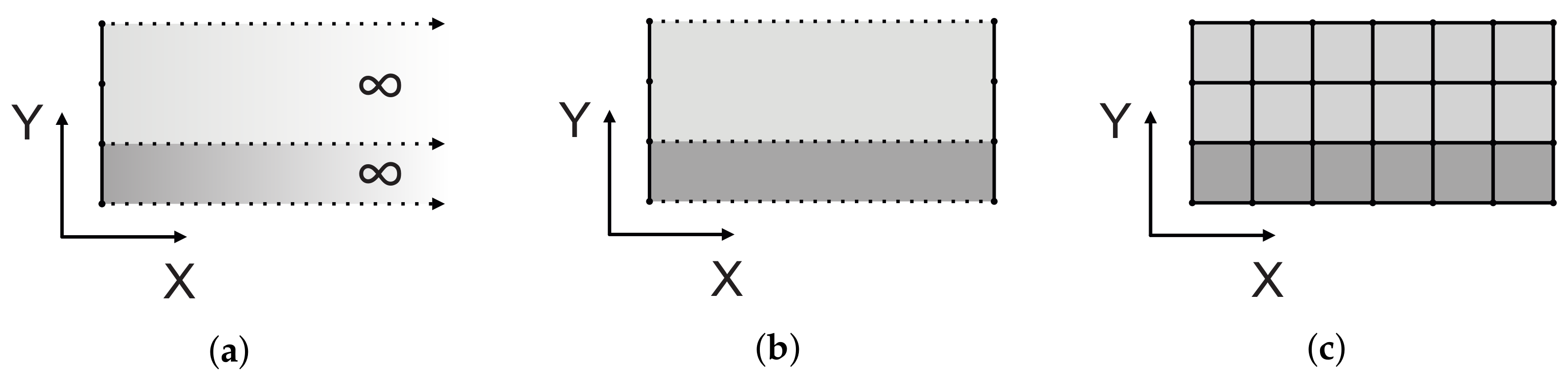
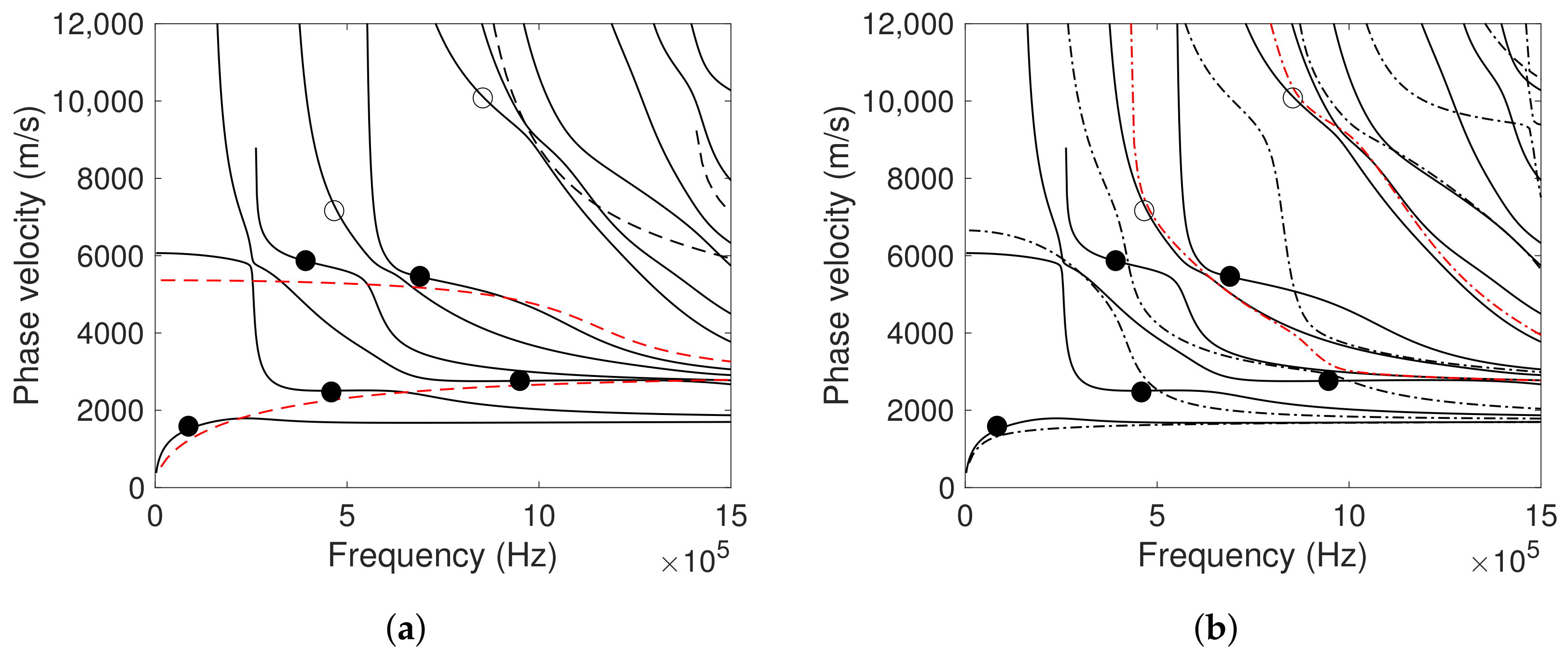
2. Methodology
3. Results
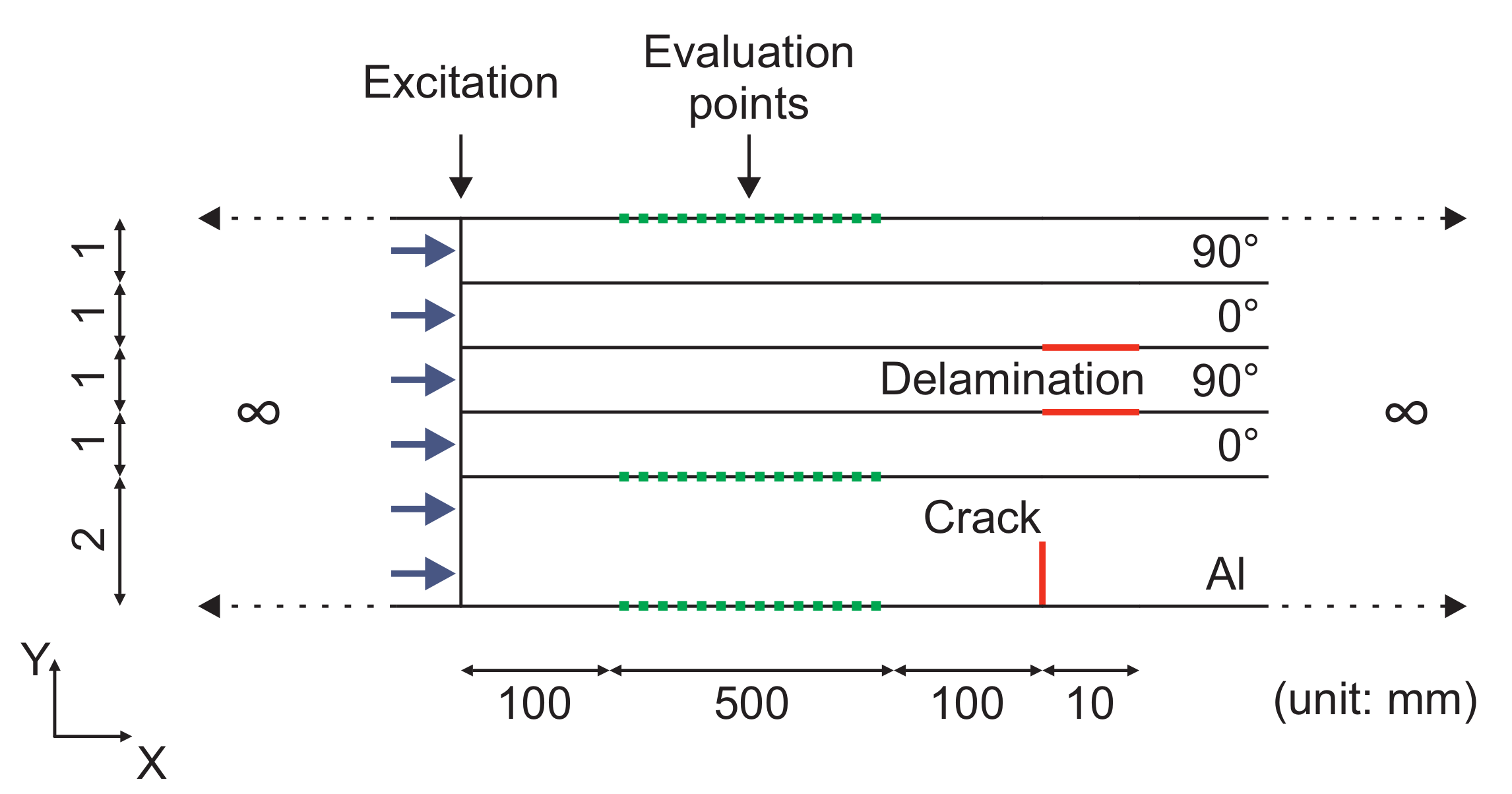
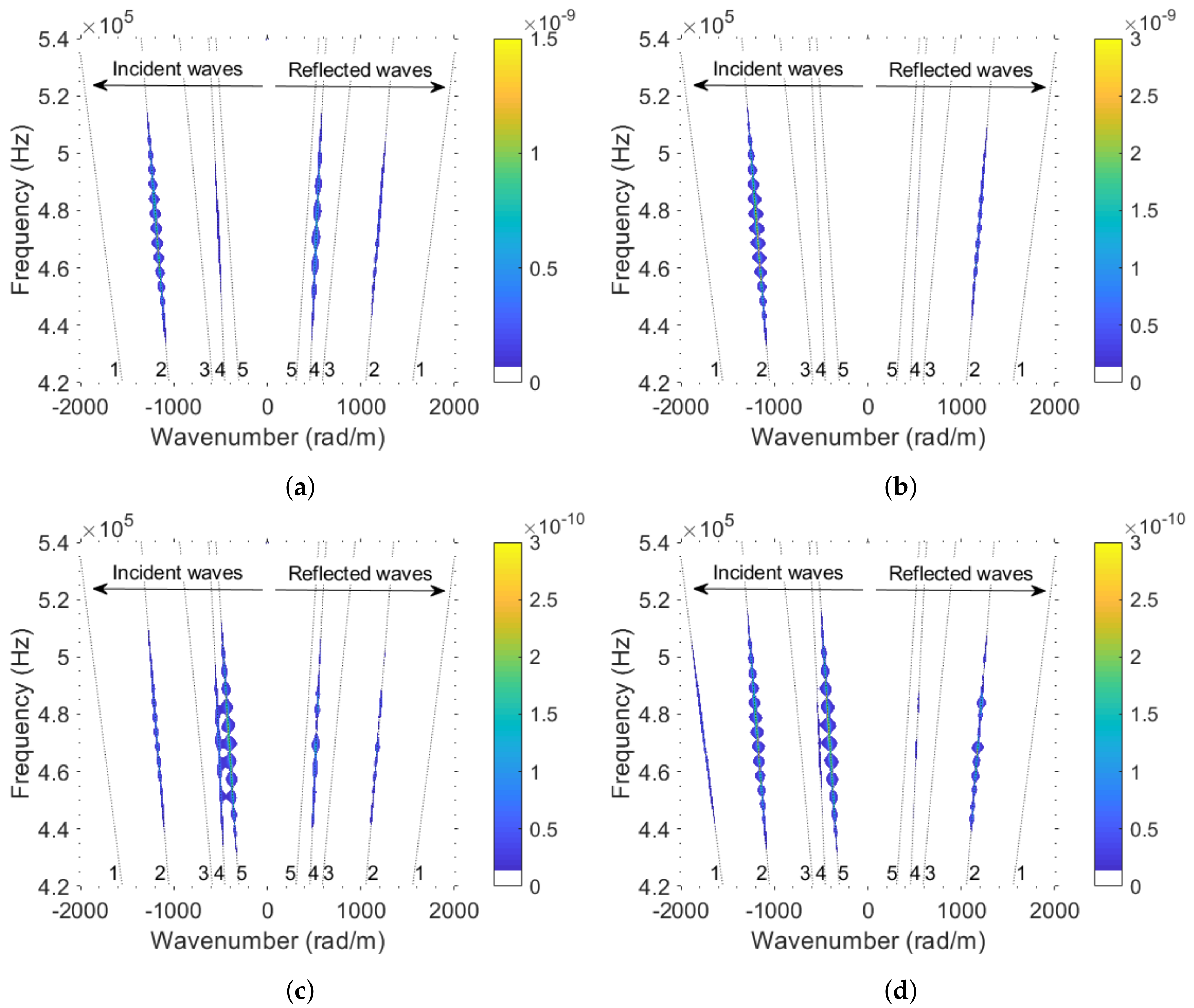
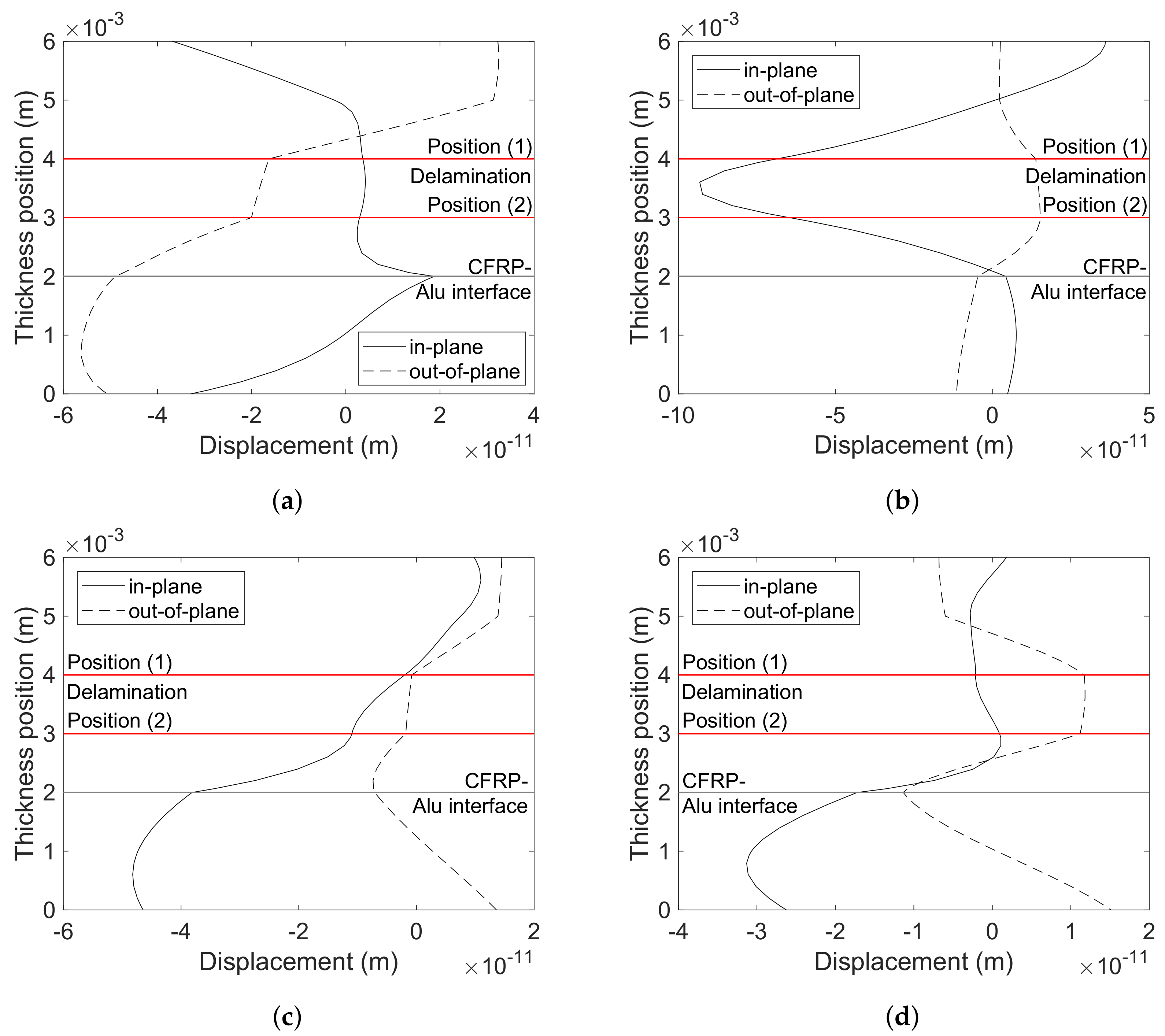
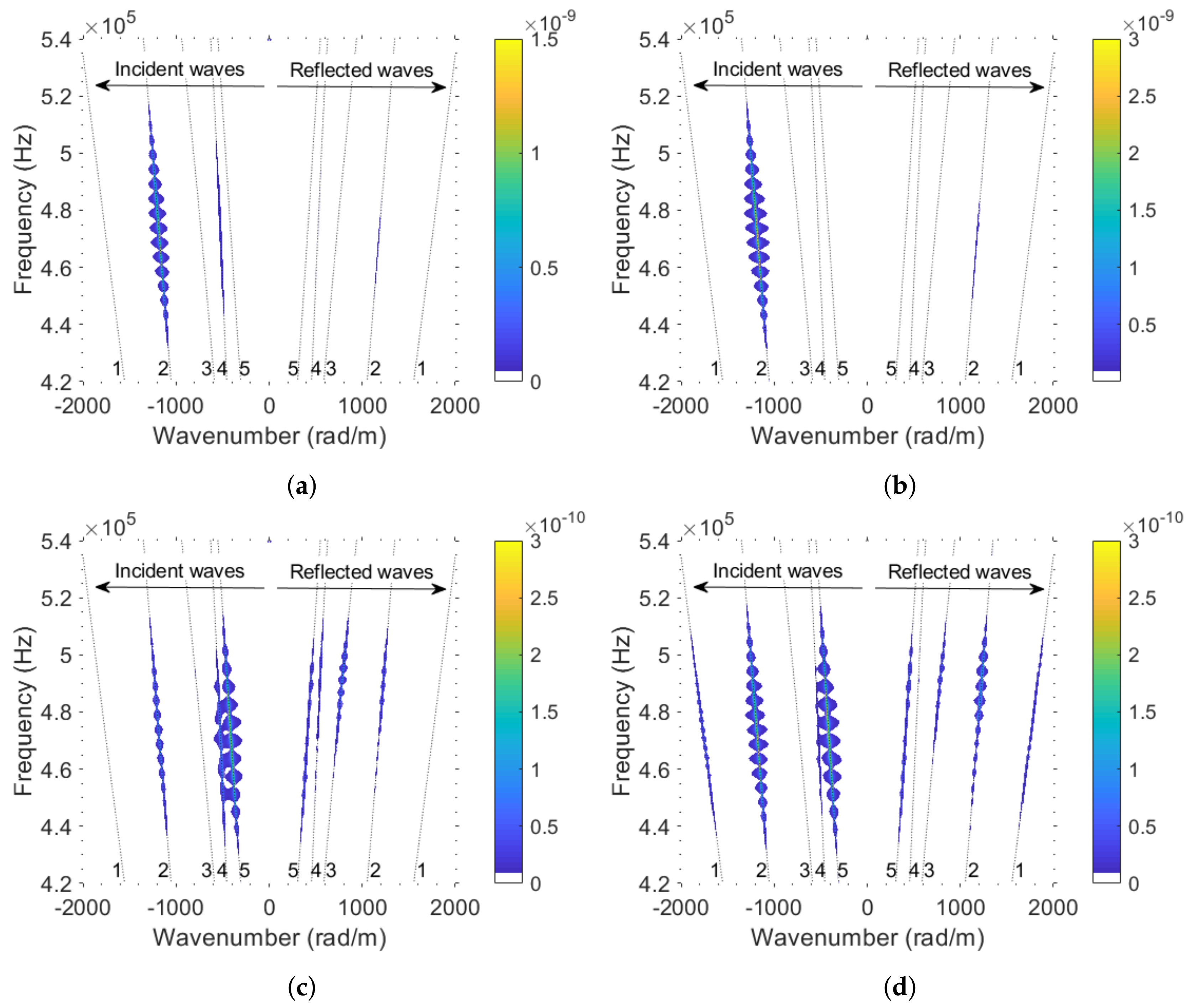
3.1. Damage in the Aluminium Liner
3.2. Damage in the CFRP Overwrap
4. Discussion
5. Conclusions
Author Contributions
Funding
Conflicts of Interest
References
- Standard Practice for Guided Wave Testing of Above Ground Steel Pipework Using Piezoelectric Effect Transduction; ASTM International: West Conshohocken, PA, USA, 2016.
- Fromme, P.; Wilcox, P.D.; Lowe, M.J.S.; Cawley, P. On the development and testing of a guided ultrasonic wave array for structural integrity monitoring. IEEE Trans. Ultrason. Ferroelectr. Freq. Control 2006, 53, 777–785. [Google Scholar] [CrossRef] [PubMed]
- Wilcox, P.; Evans, M.; Pavlakovic, B.; Alleyne, D.; Vine, K.; Cawley, P.; Lowe, M. Guided wave testing of rail. Insight Non Destr. Test. Cond. Monit. 2003, 45, 413–420. [Google Scholar] [CrossRef]
- Gao, H.; Rose, J.L. Ice detection and classification on an aircraft wing with ultrasonic shear horizontal guided waves. IEEE Trans. Ultrason. Ferroelectr. Freq. Control 2009, 56, 334–344. [Google Scholar] [CrossRef] [PubMed]
- Rose, J.; Zhu, W.; Zaidi, M. Ultrasonic NDT of titanium diffusion bonding with guided waves. Mater. Eval. 1998, 56, 535–539. [Google Scholar]
- Diamanti, K.; Soutis, C. Structural health monitoring techniques for aircraft composite structures. Prog. Aerosp. Sci. 2010, 46, 342–352. [Google Scholar] [CrossRef]
- Mitra, M.; Gopalakrishnan, S. Guided wave based structural health monitoring: A review. Smart Mater. Struct. 2016, 25. [Google Scholar] [CrossRef]
- Gao, H. Ultrasonic Guided Wave Mechanics for Composite Material Structural Health Monitoring. Ph.D. Thesis, Pennsylvania State University, State College, PA, USA, 2007. [Google Scholar]
- Yu, X.; Fan, Z.; Castaings, M.; Biateau, C. Feature guided wave inspection of bond line defects between a stiffener and a composite plate. NDT E Int. 2017, 89, 44–55. [Google Scholar] [CrossRef]
- Castaings, M.; Hosten, B. Ultrasonic guided waves for health monitoring of high-pressure composite tanks. NDT E Int. 2008, 41, 648–655. [Google Scholar] [CrossRef]
- Sause, M.G.; Hamstad, M.A.; Horn, S. Finite element modeling of lamb wave propagation in anisotropic hybrid materials. Compos. Part Eng. 2013, 53, 249–257. [Google Scholar] [CrossRef]
- Lugovtsova, Y.; Prager, J. Structural health monitoring of composite pressure vessels using guided ultrasonic waves. Insight Non Destr. Test. Cond. Monit. 2018, 60, 139–144. [Google Scholar] [CrossRef]
- Lugovtsova, Y.; Bulling, J.; Prager, J.; Boller, C. Efficient modelling of guided ultrasonic waves using the Scaled Boundary FEM towards SHM of composite pressure vessels. In Proceedings of the 9th European Workshop on Structural Health Monitoring, Manchester, UK, 10–13 July 2018. [Google Scholar]
- Mair, G.W.; Scherer, F.; Duffner, E. Concept of interactive determination of safe service life for composite cylinders by destructive tests parallel to operation. Int. J. Press. Vessel. Pip. 2014, 120–121, 36–46. [Google Scholar] [CrossRef]
- Chou, H.; Mouritz, A.; Bannister, M.; Bunsell, A. Acoustic emission analysis of composite pressure vessels under constant and cyclic pressure. Compos. Part Appl. Sci. Manuf. 2015, 70, 111–120. [Google Scholar] [CrossRef]
- Degrieck, J.; Waele, W.D.; Verleysen, P. Monitoring of fibre reinforced composites with embedded optical fibre Bragg sensors, with application to filament wound pressure vessels. NDT E Int. 2001, 34, 289–296. [Google Scholar] [CrossRef]
- Kang, D.; Kim, C.; Kim, C. The embedment of fiber Bragg grating sensors into filament wound pressure tanks considering multiplexing. NDT E Int. 2006, 39, 109–116. [Google Scholar] [CrossRef]
- Gąsior, P.; Malesa, M.; Kaleta, J.; Kujawińska, M.; Malowany, K.; Rybczyński, R. Application of complementary optical methods for strain investigation in composite high pressure vessel. Compos. Struct. 2018, 203, 718–724. [Google Scholar] [CrossRef]
- Xiao, B.; Yang, B.; Xuan, F.Z.; Wan, Y.; Hu, C.; Jin, P.; Lei, H.; Xiang, Y.; Yang, K. In-Situ Monitoring of a Filament Wound Pressure Vessel by the MWCNT Sensor under Hydraulic Fatigue Cycling and Pressurization. Sensors 2019, 19, 1396. [Google Scholar] [CrossRef]
- Saeter, E.; Lasn, K.; Nony, F.; Echtermeyer, A.T. Embedded optical fibres for monitoring pressurization and impact of filament wound cylinders. Compos. Struct. 2019, 210, 608–617. [Google Scholar] [CrossRef]
- Bulletti, A.; Giannelli, P.; Calzolai, M.; Capineri, L. An Integrated Acousto/Ultrasonic Structural Health Monitoring System for Composite Pressure Vessels. IEEE Trans. Ultrason. Ferroelectr. Freq. Control 2016, 63, 864–873. [Google Scholar] [CrossRef]
- Yaacoubi, S.; McKeon, P.; Ke, W.; Declercq, N.; Dahmene, F. Towards an Ultrasonic Guided Wave Procedure for Health Monitoring of Composite Vessels: Application to Hydrogen-Powered Aircraft. Materials 2017, 10, 1097. [Google Scholar] [CrossRef]
- Yang, B.; Xiang, Y.; Xuan, F.Z.; Hu, C.; Xiao, B.; Zhou, S.; Luo, C. Damage localization in hydrogen storage vessel by guided waves based on a real-time monitoring system. Int. J. Hydrogen Energy 2019. [Google Scholar] [CrossRef]
- Lowe, M.J.S. Matrix techniques for modeling ultrasonic waves in multilayered media. IEEE Trans. Ultrason. Ferroelectr. Freq. Control 1995, 42, 525–542. [Google Scholar] [CrossRef]
- Kausel, E. Wave propagation in anisotropic layered media. Int. J. Numer. Methods Eng. 1986, 23, 1567–1578. [Google Scholar] [CrossRef]
- Dong, S.B.; Nelson, R.B. On Natural Vibrations and Waves in Laminated Orthotropic Plates. J. Appl. Mech. 1972, 39, 739–745. [Google Scholar] [CrossRef]
- Dong, S.B.; Huang, K.H. Edge Vibrations in Laminated Composite Plates. J. Appl. Mech. 1985, 52, 433–438. [Google Scholar] [CrossRef]
- Gravenkamp, H.; Song, C.; Prager, J. A numerical approach for the computation of dispersion relations for plate structures using the Scaled Boundary Finite Element Method. J. Sound Vib. 2012, 331, 2543–2557. [Google Scholar] [CrossRef]
- Xu, K.; Ta, D.; Su, Z.; Wang, W. Transmission analysis of ultrasonic Lamb mode conversion in a plate with partial-thickness notch. Ultrasonics 2014, 54, 395–401. [Google Scholar] [CrossRef]
- Fellinger, P.; Marklein, R.; Langenberg, K.; Klaholz, S. Numerical modeling of elastic wave propagation and scattering with EFIT—Elastodynamic finite integration technique. Wave Motion 1995, 21, 47–66. [Google Scholar] [CrossRef]
- Schubert, F.; Peiffer, A.; Köhler, B.; Sanderson, T. The elastodynamic finite integration technique for waves in cylindrical geometries. J. Acoust. Soc. Am. 1998, 104, 2604–2614. [Google Scholar] [CrossRef]
- Leckey, C.A.; Rogge, M.D.; Miller, C.A.; Hinders, M.K. Multiple-mode Lamb wave scattering simulations using 3D elastodynamic finite integration technique. Ultrasonics 2012, 52, 193–207. [Google Scholar] [CrossRef]
- Luchinsky, D.G.; Hafiychuk, V.; Smelyanskiy, V.N.; Kessler, S.; Walker, J.; Miller, J.; Watson, M. Modeling wave propagation and scattering from impact damage for structural health monitoring of composite sandwich plates. Struct. Health Monit. 2013, 12, 296–308. [Google Scholar] [CrossRef]
- Willberg, C.; Duczek, S.; Vivar-Perez, J.M.; Ahmad, Z.A.B. Simulation Methods for Guided Wave-Based Structural Health Monitoring: A Review. Appl. Mech. Rev. 2015, 67, 010803. [Google Scholar] [CrossRef]
- Gravenkamp, H.; Prager, J.; Saputra, A.A.; Song, C. The simulation of Lamb waves in a cracked plate using the scaled boundary finite element method. J. Acoust. Soc. Am. 2012, 132, 1358–1367. [Google Scholar] [CrossRef] [PubMed]
- Gravenkamp, H. Efficient simulation of elastic guided waves interacting with notches, adhesive joints, delaminations and inclined edges in plate structures. Ultrasonics 2018, 82, 101–113. [Google Scholar] [CrossRef] [PubMed]
- Bunsell, A.R. Composite pressure vessels supply an answer to transport problems. Reinf. Plast. 2006, 50, 38–41. [Google Scholar] [CrossRef]
- Scott, A.; Clinch, M.; Hepples, W.; Kalantzis, N.; Sinclair, I.; Spearing, S.M. Advanced micromechanical analysis of highly loaded hybrid composite structures. In Proceedings of the 17th International Conference on Composite Materials, Edinburgh, UK, 27–31 July 2009. [Google Scholar]
- Changliang, Z.; Mingfa, R.; Wei, Z.; Haoran, C. Delamination prediction of composite filament wound vessel with metal liner under low velocity impact. Compos. Struct. 2006, 75, 387–392. [Google Scholar] [CrossRef]
- Matemilola, S.A.; Stronge, W.J. Low-Speed Impact Damage in Filament-Wound CFRP Composite Pressure Vessels. J. Press. Vessel. Technol. 1997, 119, 435–443. [Google Scholar] [CrossRef]
- Wilcox, P.D. Lamb Wave Inspection of Large Structures Using Permanently Attached Transducers. Ph.D. Thesis, Imperial College London, London, UK, 1998. [Google Scholar]
- Monkhouse, R.; Wilcox, P.; Cawley, P. Flexible interdigital PVDF transducers for the generation of Lamb waves in structures. Ultrasonics 1997, 35, 489–498. [Google Scholar] [CrossRef]
- Ueberschlag, P. PVDF piezoelectric polymer. Sens. Rev. 2001, 21, 118–126. [Google Scholar] [CrossRef]
- Seminara, L.; Pinna, L.; Valle, M.; Basiricò, L.; Loi, A.; Cosseddu, P.; Bonfiglio, A.; Ascia, A.; Biso, M.; Ansaldo, A.; et al. Piezoelectric Polymer Transducer Arrays for Flexible Tactile Sensors. IEEE Sens. J. 2013, 13, 4022–4029. [Google Scholar] [CrossRef]
- Bulletti, A.; Capineri, L. Interdigital Piezopolymer Transducers for Time of Flight Measurements with Ultrasonic Lamb Waves on Carbon-Epoxy Composites under Pure Bending Stress. J. Sens. 2015. [Google Scholar] [CrossRef]
- Ren, B.; Lissenden, C.J. PVDF Multielement Lamb Wave Sensor for Structural Health Monitoring. IEEE Trans. Ultrason. Ferroelectr. Freq. Control 2016, 63, 178–185. [Google Scholar] [CrossRef] [PubMed]
- Giannelli, P.; Bulletti, A.; Capineri, L. Charge-mode interfacing of piezoelectric interdigital Lamb wave transducers. Electron. Lett. 2016, 52, 894–896. [Google Scholar] [CrossRef]


| (kg/m3) | (GPa) | (GPa) | (GPa) | ||
|---|---|---|---|---|---|
| 1490 | 121 | 8.6 | 4.7 | 0.27 | 0.4 |
| (kg/m3) | E (GPa) | |
|---|---|---|
| 2770 | 70 | 0.33 |
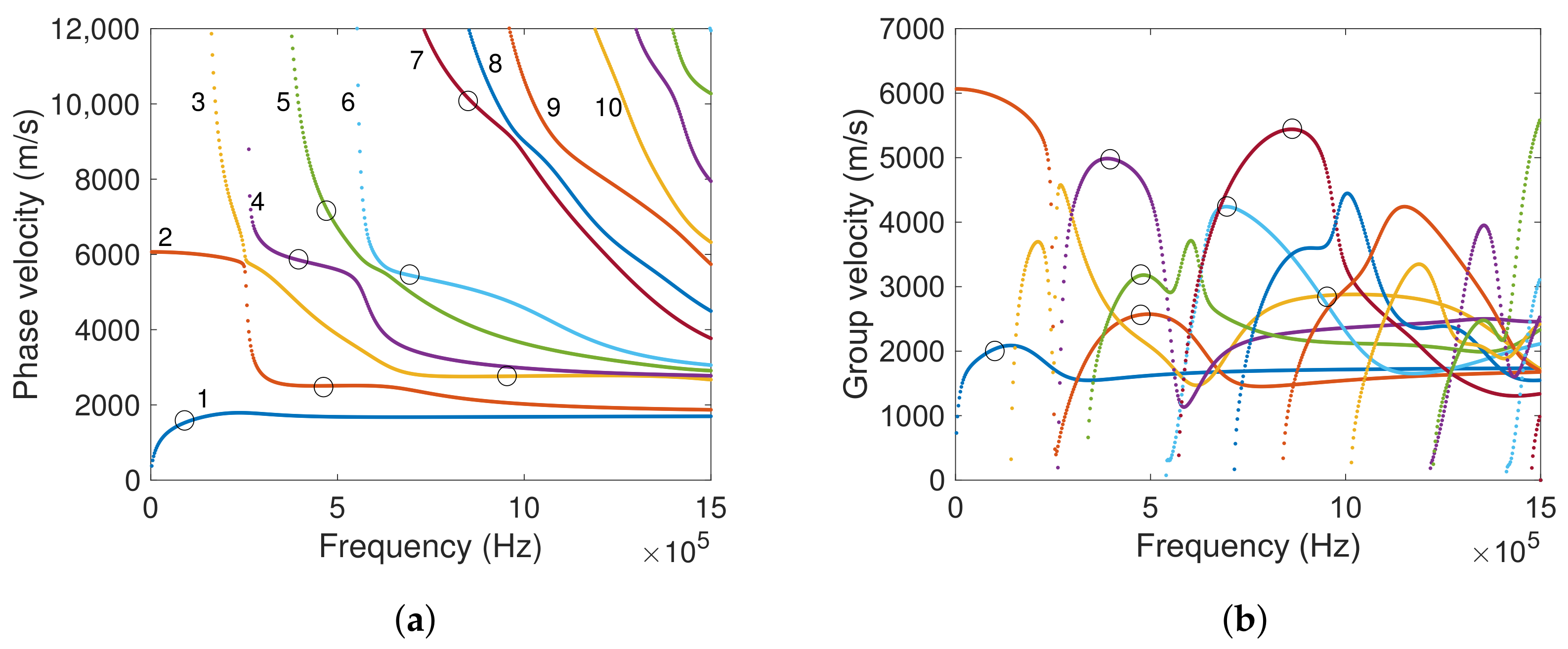
| Mode | Frequency kHz | Group Velocity m/s | Phase Velocity m/s | Wavelength mm | Number of Cycles |
|---|---|---|---|---|---|
| 1 | 100 | 2033 | 1562 | 15.6 | 10 |
| 2 | 475 | 2565 | 2507 | 5.3 | 20 |
| 3 | 950 | 2864 | 2761 | 2.9 | 30 |
| 4 | 400 | 4981 | 5839 | 14.6 | 20 |
| 5 | 475 | 3175 | 7132 | 15 | 20 |
| 6 | 700 | 4238 | 5431 | 7.8 | 20 |
| 7 | 860 | 5440 | 10,005 | 11.6 | 30 |
| Mode | Frequency kHz | Wavelength mm | Crack in Aluminium | Delamination at Position (1) | Delamination at Position (2) |
|---|---|---|---|---|---|
| 1 | 100 | 15.6 | ✓ | ✓ | ✓ |
| 2 | 475 | 5.3 | ✓ | ✓ | ✓ |
| 3 | 950 | 2.9 | ✓ | ✓ | ✓ |
| 4 | 400 | 14.6 | ✓ | ✓ | ✗ |
| 5 | 475 | 15 | ✗ | ✓ | ✓ |
| 6 | 700 | 7.8 | ✓ | ✗ | ✗ |
| 7 | 860 | 11.6 | ✗ | ✓ | ✗ |
© 2019 by the authors. Licensee MDPI, Basel, Switzerland. This article is an open access article distributed under the terms and conditions of the Creative Commons Attribution (CC BY) license (http://creativecommons.org/licenses/by/4.0/).
Share and Cite
Lugovtsova, Y.; Bulling, J.; Boller, C.; Prager, J. Analysis of Guided Wave Propagation in a Multi-Layered Structure in View of Structural Health Monitoring. Appl. Sci. 2019, 9, 4600. https://doi.org/10.3390/app9214600
Lugovtsova Y, Bulling J, Boller C, Prager J. Analysis of Guided Wave Propagation in a Multi-Layered Structure in View of Structural Health Monitoring. Applied Sciences. 2019; 9(21):4600. https://doi.org/10.3390/app9214600
Chicago/Turabian StyleLugovtsova, Yevgeniya, Jannis Bulling, Christian Boller, and Jens Prager. 2019. "Analysis of Guided Wave Propagation in a Multi-Layered Structure in View of Structural Health Monitoring" Applied Sciences 9, no. 21: 4600. https://doi.org/10.3390/app9214600
APA StyleLugovtsova, Y., Bulling, J., Boller, C., & Prager, J. (2019). Analysis of Guided Wave Propagation in a Multi-Layered Structure in View of Structural Health Monitoring. Applied Sciences, 9(21), 4600. https://doi.org/10.3390/app9214600