Analysis of a Collision-Energy-Based Method for the Prediction of Ice Loading on Ships


Abstract
:1. Introduction
- Category A, for ships allowed to operate in at least medium-thick first-year ice.
- Category B, for ships allowed to operate in at least thin first-year ice.
- Category C, for ships allowed to operate in ice conditions less severe than those included in Categories A or B.
- “Guidelines for the approval of alternatives and equivalents as provided for in various IMO instruments”, MSC.1/Circ.1455 [4].
- “Guidelines on alternative design and arrangements for SOLAS chapters II-1 and III, MSC.1/Circ.1212 [5].
- “Guidelines on alternative design and arrangements for fire safety”, MSC/Circ.1002 [6].
- How do assumptions behind the modelling of the collision scenario and the description of the operating conditions affect the ice load estimate?
- What collision scenario assumptions should be applied to obtain reliable ice load estimates for typical operation in level and broken ice?
- Issues concerning hydrodynamic effects. These are assumed to have a limited effect on the types of collision scenarios considered [13].
- Issues concerning structural resistance.
- Secondary impacts (i.e., reflected collisions). Daley & Liu [19], among others, demonstrate that when operating in thick ice, reflected collisions may result in critical loads, in particular on the mid-ship area.
- Moving loads along the hull that may result from a collision with pack ice, glacial ice, or ice channel edges are not considered. Kendrick et al. [20] and Quinton & Daley [21] indicate that moving ice loads may cause more damage than stationary loads of similar magnitude. Consideration of moving loads would require the consideration of additional factors such as sliding contact, nonlinear geometric and material behaviours in structural components, requiring the application of the finite element analysis [22].
2. Background
2.1. The Popov Method
2.2. Collision Scenario
- An impact between a ship and an ice floe. According to Enkvist, et al. [25] this is the most common collision scenario for merchant ships. As per Table 1, in this scenario, the kinetic energy of the ship is partially converted into the kinetic energy of the ice floe and partially consumed in crushing the ice edge . , , and are calculated in accordance with the formulas presented in Table 1 (Case 1), where and are the reduced masses of the ship and the ice floe, and the parameters and correspond to the reduced speeds of the ship and the ice floe.
- An impact between a ship and the edge of an ice field. In this scenario, defined as case two in Table 1, the edge of the ice field is crushed, and the ice field bends due to the vertical component of the contact force . In this scenario, the ship’s kinetic energy is consumed by the crushing and by the bending of the ice field . , , and are calculated in accordance with the formulas presented in Table 1 (Case 2), where , is the specific weight of ice, is flexural stiffness of an ice plate, is the elastic modulus of ice, is the ice thickness, is Poisson ratio for ice.
2.3. Ship–Ice Contact and Ice Crushing Pressure
2.4. Contact Geometry
- Round contact geometry. This model, which is behind the design scenario of the ice class standards of the Russian Maritime Register of Shipping (RMRS), corresponds to an oblique collision with a rounded ice edge [12]. Related geometrical parameters are the radius of ice floe ], the waterline angle and normal frame angle . Parameters and are dependent on the hull form, whereas R is dependent on the ice conditions. In the RMRS ice class rules, R is assumed at .
- Angular (wedge) contact geometry. This model is applied in the design scenario of the PC rules [14]. Related geometrical parameters are the ice edge opening angle , waterline angle and normal frame angle . According to Popov, et al. [9], can be determined by observation of ice segments broken by a ship. Alternatively, can be determined by numerical simulations [36].
- Symmetric v wedge contact geometry. This model can be applied to assess ice loads from beaching impacts, i.e., when a ship is ramming an ice sheet so that the bow of the ship rises upwards onto the ice sheet [34]. Related geometrical parameters are waterline angle , frame angle and stem angle , all of which depend on the hull form at the point of impact.
- Right-apex oblique contact geometry. This model, defined by Daley [34], corresponds to continuous operation in ice without ramming. Related geometrical parameters are waterline angle , normal frame angle , stem angle and frame angle , all of which depend on the hull form at the point of impact.
- Spherical contact geometry. This model can be applied for the assessment of ice loads on a bulbous bow [20]. Related geometrical parameters are the contact radius , waterline angle and the normal frame angle , all of which depend on the hull form at the point of impact.
- Pyramid contact geometry. This model can be applied to assess ice loads from ship–iceberg interactions resulting in structural deformations [35]. Related geometrical parameters are the ice edge opening angle , waterline angle and normal frame angle .
2.5. Identification of Assumptions Behind the Popov Method and the PC Rules
- Assumptions related to the definition of the ship–ice collision scenario. The Popov Method assumes two types of ship–ice collision scenarios defined in Table 1: (a) Ship–ice floe collision, and (b) ship–ice field collision. The PC rules, on the other hand, assume a single type of ship–ice collision scenario, namely a glancing impact with thick level ice.
- Assumptions related to the definition of contact pressure. For typical speeds of ships operating in ice, Popov et al. [9] suggested that the contact pressure can be assumed equal to the ice crushing strength over the whole contact area. Accordingly, the maximum ice load corresponding to the maximum indentation depth can be defined as perHowever, this is a simplification, as the crushing strength of ice depends on multiple factors and varies between [9]. In the PC rules, on the other hand, the contact pressure is assumed to correspond to the pressure-area relationship following:where is average pressure acting on 1 (class dependent), is the contact area, and is a coefficient empirically determined as −0.1.
- Assumptions related to the definition of the contact geometry case. The application of specific contact geometries requires making assumptions regarding individual contact geometry parameters. When applying the round contact geometry model, Popov et al. [9] recommend the use of R-values in the range of 10–40 m. For angular contact geometry, Popov et al. [9] recommend the use of ice opening angle values () in the range of 45°–145°. In the PC rules the assumed contact geometry case is always angular (also referred to as a wedge shape) with a constant value of 150° [37].
- Assumptions related to the definition of the size of the nominal ship–ice contact area. As per the Popov Method, the nominal ship–ice contact area is assumed to be dependent on the form of the hull and ice at the point of impact as per Equation (2). The PC rules, on the other hand, assuming a wedge-shaped contact geometry, assume a single nominal contact area defined perNaturally, this is a simplification as the actual contact area depends strongly on the assumed contact geometry, and thus on the prevailing ice conditions and the hull form.
- Assumptions related to the definition of load length and load height. The load length and load height, both of which affect the structural requirements in accordance with the PC rules, are derived as a function of the indentation depth [34,39]. In the PC rules, the design load length is assumed to be defined perwhere is the nominal contact length of the assumed wedge-shaped contact geometry and is an ice spalling parameter with an empirically determined value of 0.7. The ice spalling parameter accounts for ice edge spalling effects by reducing the size of the contact patch. Although this parameter has a significant effect on the determined scantling requirements, no justification for the assumed value of is found in the literature [12]. The design load height is related to the design load length as perwhere is a design patch aspect ratio used to simplify the nominal contact area to an equivalent area of a rectangular patch.
3. Research Method
3.1. Ship–ice Interaction and Material Parameters
- Ship parameters including hull particulars: Length, beam, draft, displacement, hull angles.
- Impact parameters including impact location and speed.
- Environmental parameters including ice floe size, ice thickness and air temperature.
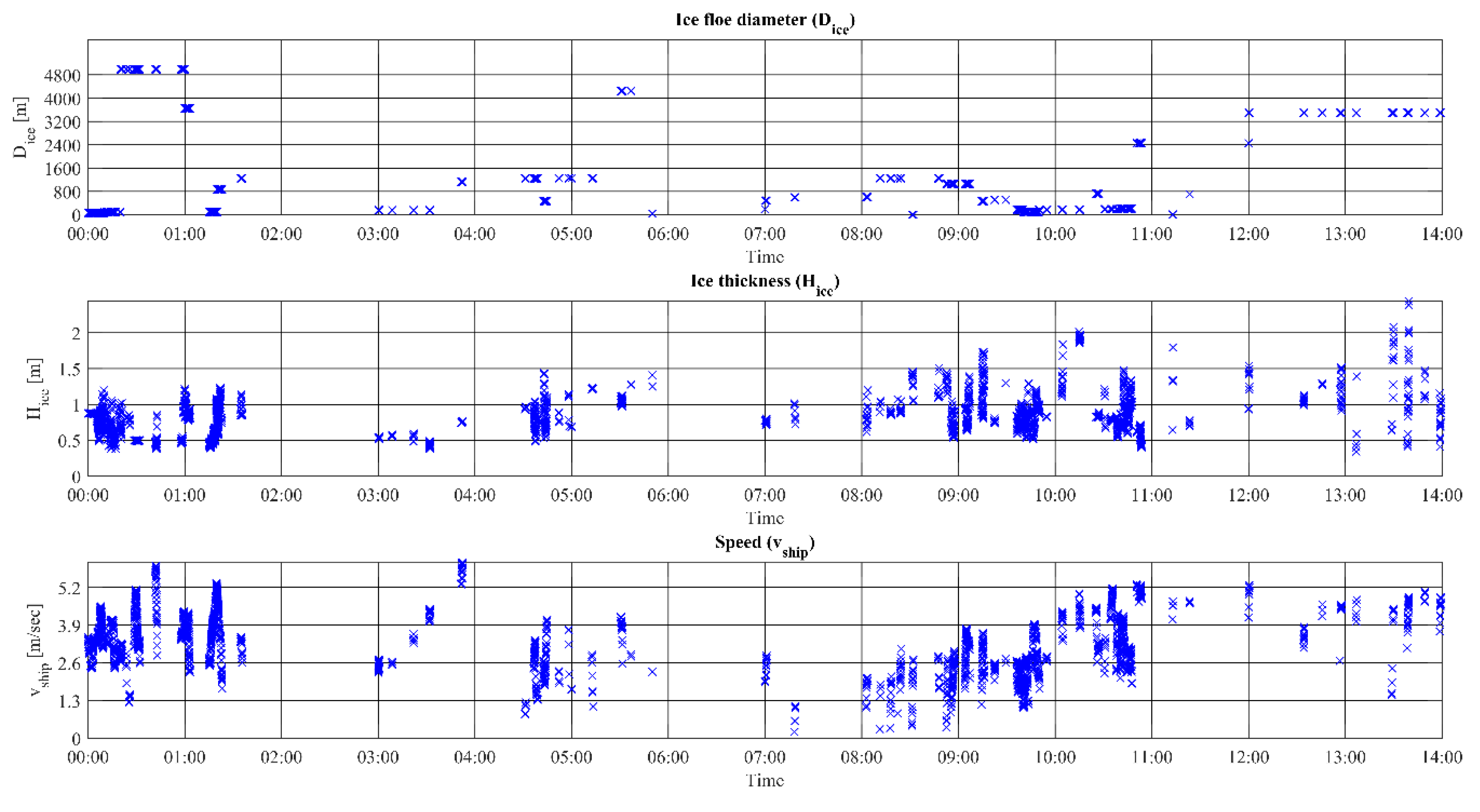
- Data set A. Measurements from 10.12.2013 representing continuous operation in ice as well as specific manoeuvres such as ramming and reversing in ice. An extract of data set A is presented in Figure 3.
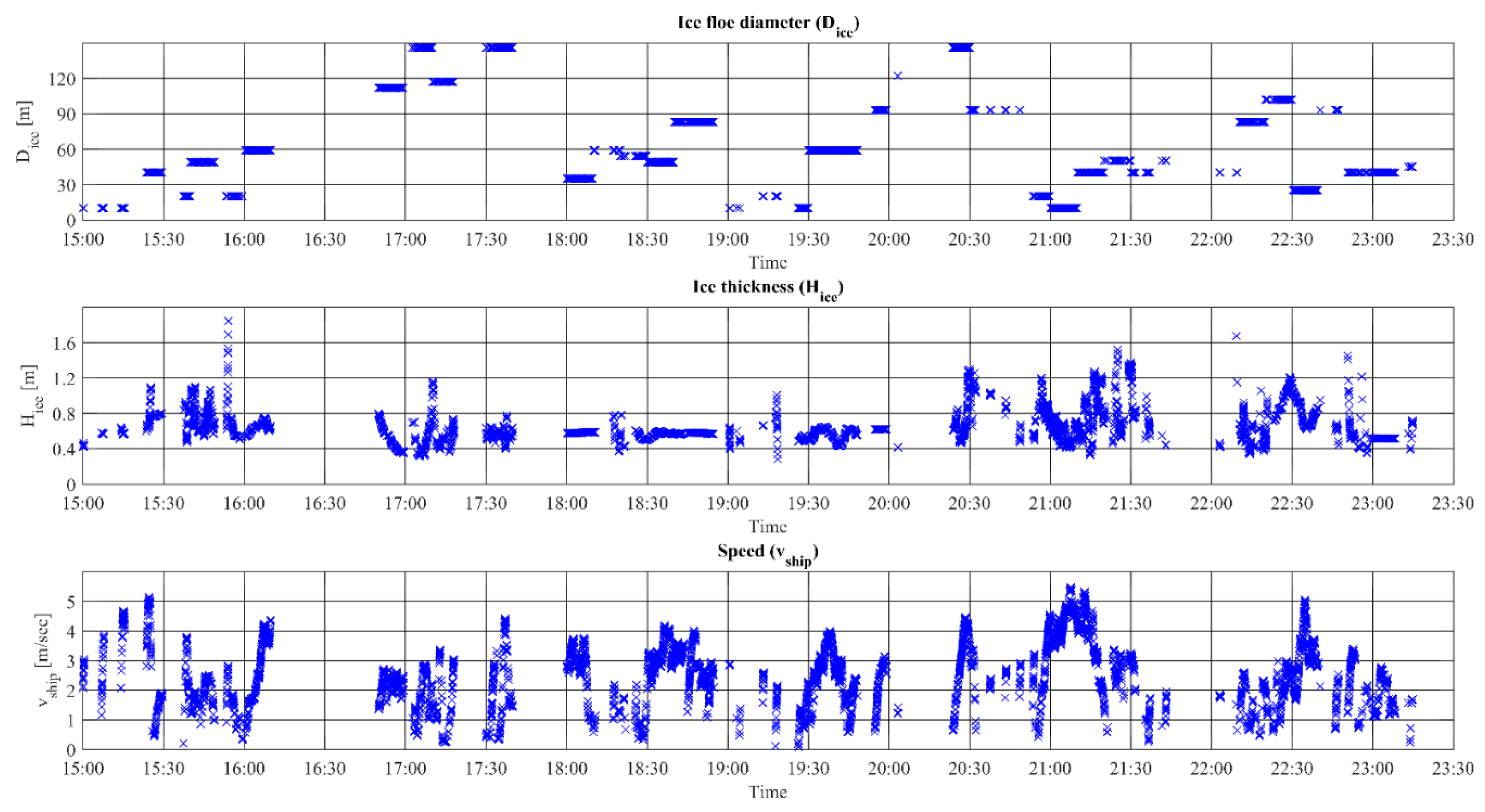
- Data set B. Measurements from 20.12.2013 representing mainly continuous operation in ice. An extract of data set A is presented in Figure 4.
3.2. Collision Scenarios
3.3. Ice Load Parameters
3.4. Line Loads
4. Results
4.1. Analysis of Data Set A
4.2. Analysis of Data Set B
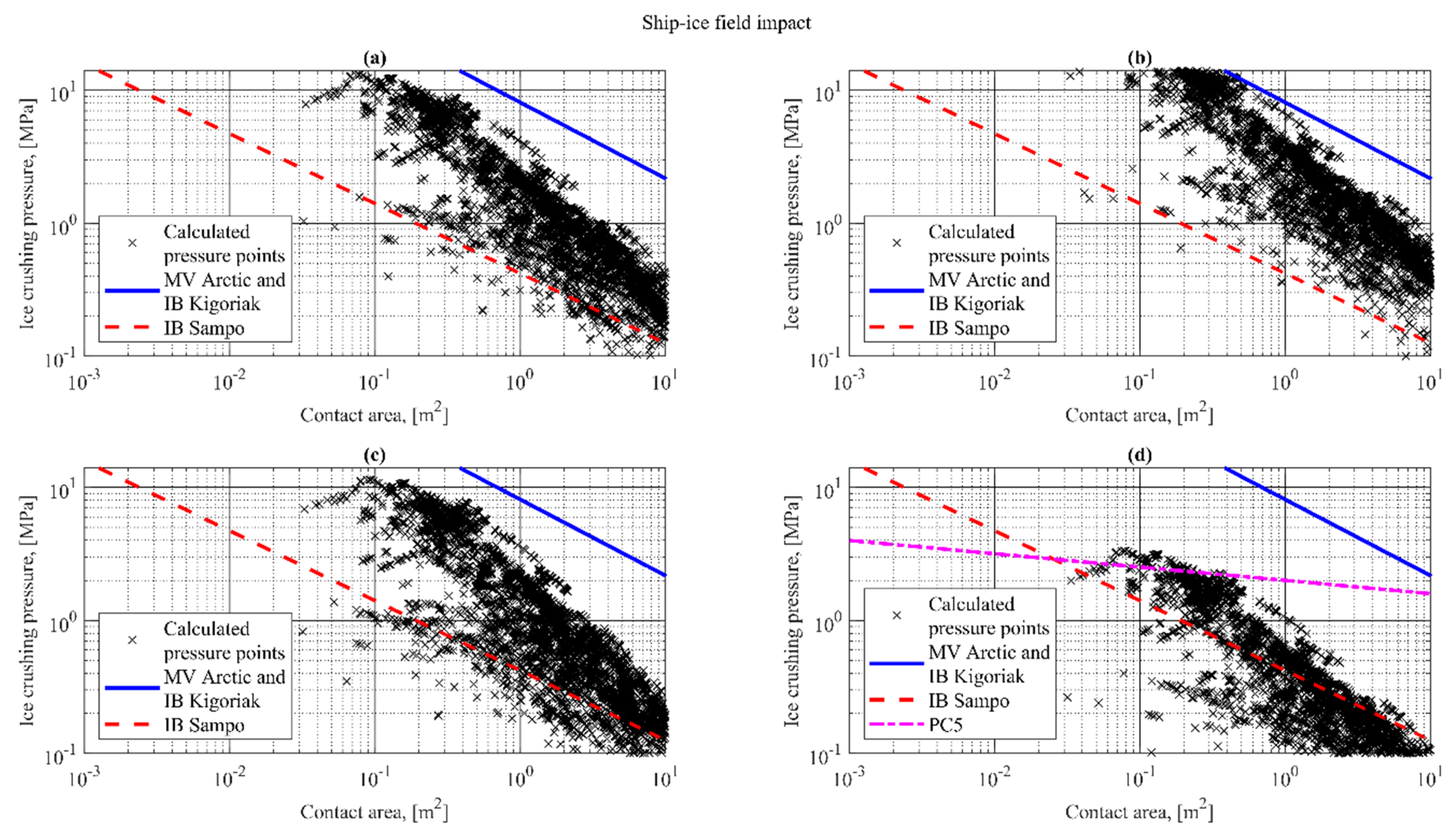
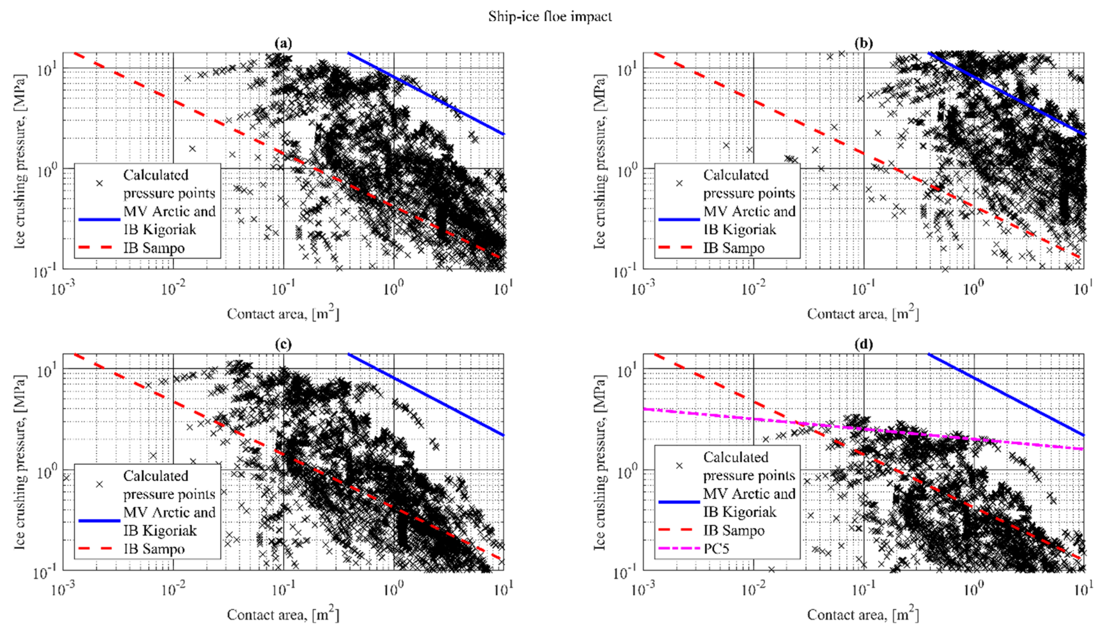
4.3. Ice Crushing Strength and Pressure
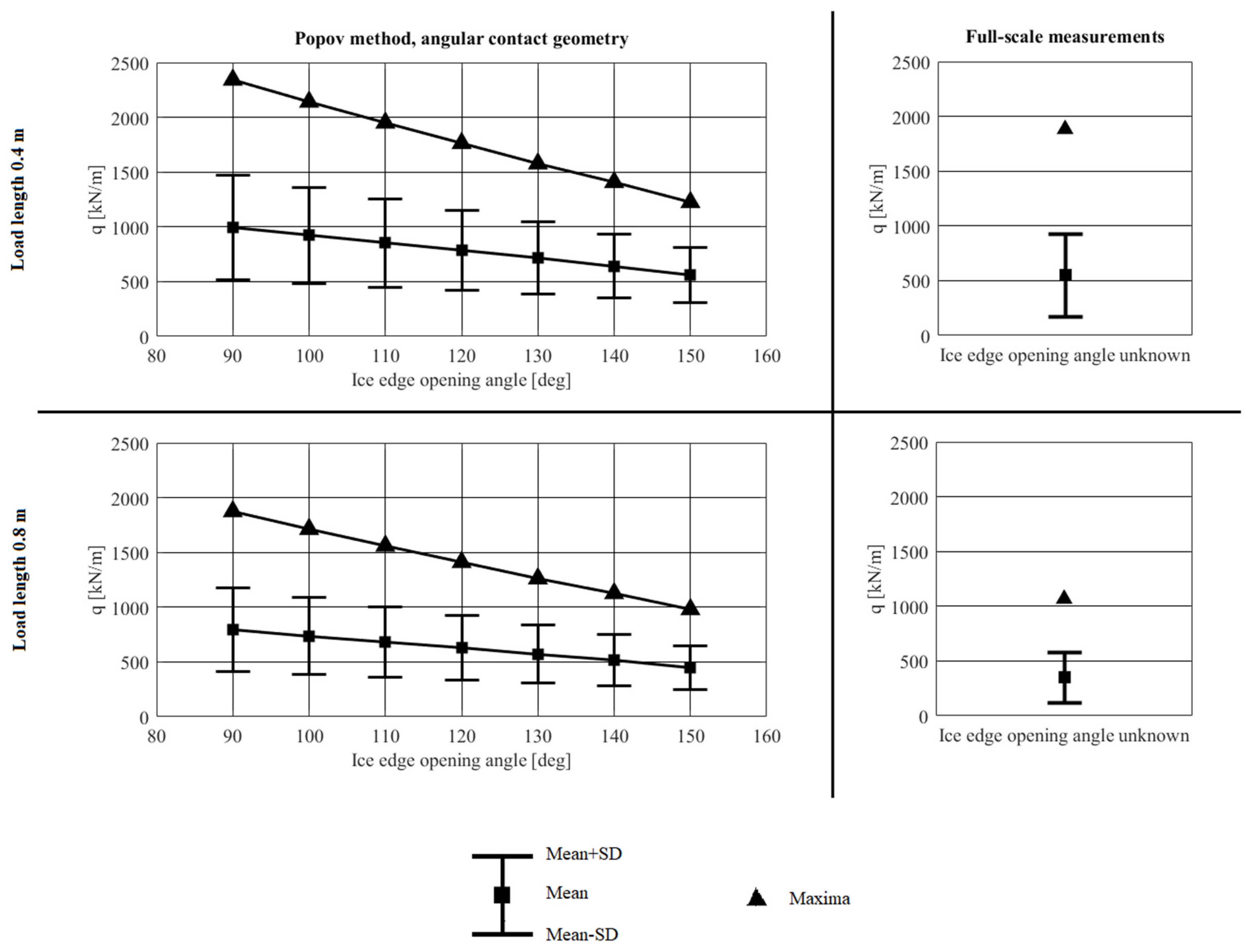
4.4. Influence of the Assumed Ice Edge Opening Angle
- For one-frame spacing (load length = 0.4 m), a good agreement with the mean and maximum of the measurements is obtained for Φ-values around 150° and 110°, respectively.
- For two-frame spacing (load length = 0.8 m), a good agreement with the mean and maximum of the measurements is obtained for Φ-values around 150° and 140°, respectively.
5. Discussion and Conclusions
Author Contributions
Funding
Acknowledgments
Conflicts of Interest
Abbreviations
| Polar Code | International Code for Ships Operating in Polar Waters |
| IMO | International Maritime Organization |
| IACS | International Association of Classification Societies |
| PC | Polar Class |
| SOLAS | International Convention for the Safety of Life at Sea |
| MARPOL | International Convention for the Prevention of Pollution from Ships |
| FR | Functional Requirements |
| RMRS | Russian Maritime Register of Shipping |
| DOF | Degree of Freedom |
| MV | Motor Vessel |
| IB | Icebreaker |
| RQ | Research Question |
| Notations | |
| Total reduced mass of the ship–ice system: | |
| Total ice load, | |
| Nominal contact area, | |
| Indentation depth, | |
| Time, | |
| Contact pressure, | |
| Exponent of the configuration of the ice edge at the point of impact | |
| Coefficient of the geometric parameters of the ship and ice | |
| Ice compressive strength, | |
| Indentation coefficient | |
| Kinetic energy of the ship, reduced toward the line of impact, | |
| Kinetic energy of the ice, reduced toward the line of impact, | |
| Ice crushing related work, | |
| Potential bending strain energy of a semi-infinite ice plate, | |
| Reduced masses for the ship and ice floe, [t] | |
| , | Reduced speeds for the ship and ice floe, |
| Vertical component of contact force, | |
| Specific weight of ice, | |
| Flexural stiffness of ice plate, | |
| Elastic modulus of ice, | |
| Ice thickness, | |
| Poisson ratio for ice | |
| Ice crushing strength, | |
| Maximum indentation depth, | |
| Radius of an ice floe, | |
| Ice edge opening angle, | |
| Projected horizontal indentation depth, | |
| Projected vertical indentation depth, | |
| α | Waterline angle, |
| β | Frame angle, |
| Normal frame angle, | |
| Stem angle, | |
| Contact radius, | |
| Average pressure, | |
| Average pressure on 1 , | |
| Exponent in pressure-area relationship | |
| Design contact length, | |
| Nominal contact length, | |
| Empirical ice spalling parameter | |
| Design load height, | |
| Design patch aspect ratio | |
| Load length, | |
| Load height, | |
| Ice crushing pressure, | |
| Line load, | |
| Load length for round contact geometry, | |
| Difference between the calculated and measured mean values, [%] | |
| Difference between the calculated and measured maximum values, [%] |
References
- IMO. International Code for Ships Operating in Polar Waters (Polar Code); International Maritime Organization: London, UK, 2015. [Google Scholar]
- Kvålsvold, J. NSR Transit Shipping—A Risk Based Approach. In Northern Sea Route: New Opportunities; Det Norske Veritas: Moscow, Russia, 2012. [Google Scholar]
- IMO. Resolution MSC.386(94). Amendments of the International Convention for the Safety of Life at Sea, 1974, as Amended; International Maritime Organization: London, UK, 2014. [Google Scholar]
- IMO. Guidelines for the Approval of Alternatives and Equivalents as Provided for in Various IMO Instruments; International Maritime Organization: London, UK, 2013. [Google Scholar]
- IMO. Guidelines on Alternative Design and Arrangements for SOLAS Chapters II-1 and III. MSC.1/Circ.1212; International Maritime Organization: London, UK, 2006. [Google Scholar]
- IMO. Guidelines on Alternative Design and Arrangements for Fire Safety; MSC/Circ.1002; International Maritime Organization: London, UK, 2001. [Google Scholar]
- Daley, C. Oblique ice collision loads on ships based on energy methods. Ocean. Eng. Int. 2001, 5, 67–72. [Google Scholar]
- Kujala, P. Ice Loading on Ship Hull. In Encyclopedia of Maritime and Offshore Engineering; John Wiley & Sons: Hoboken, NJ, USA, 2017. [Google Scholar]
- Popov, Y.; Faddeyev, O.; Kheisin, D.; Yalovlev, A. Strength of Ships Sailing in Ice; Sudostroenie Publishing House: Leningrad, The Netherlands, 1967. [Google Scholar]
- Daley, C. Background Notes to Design Ice Loads; IACS Ad-hoc Group on Polar Class Ships, Transport Canada: Ottawa, ON, Canada; Memorial University: St. John’s, NL, Canada, 2000.
- Tunik, A. Dynamic Ice Loads on a Ship; International Association for Hydraulic Research: Hamburg, Germany, 1984. [Google Scholar]
- Kim, E.; Amdahl, J. Understanding the effect of the assumptions on shell plate thickness for Arctic ships. Trondheim. In Proceedings of the 23rd International Conference on Port and Ocean Engineering under Arctic Conditions, Trondheim, Norway, 14–18 June 2015; pp. 249–261. [Google Scholar]
- Huang, Y.; Qiu, W.; Ralph, F.; Fuglem, M. Improved Added Mass Modeling for Ship-Ice Interactions Based on Numerical Results and Analytical Models. In Proceedings of the Offshore Technology Conference, Houston, TX, USA, 5 May 2016. [Google Scholar]
- Dolny, J. Methodology for Defining Technical Safe Speeds for Light Ice-Strengthened Government Vessels Operating in Ice; Report No. SR—1475; The Ship Structure Committee: Washington, DC, USA, 2018. [Google Scholar]
- Storheim, M. Structural Response in Ship-Platform and Ship-Ice Collisions. Ph.D. Thesis, NTNU, Trondheim, Norway, January 2016. [Google Scholar]
- Kujala, P.; Goerlandt, F.; Way, B.; Smith, D.; Yang, M.; Khan, F.; Veitch, B. Review of risk-based design for ice-class ships. Mar. Struct. 2019, 63, 181–195. [Google Scholar] [CrossRef]
- Sazidy, M.; Daley, C.; Colbourne, B.; Wang, J. Effect of Ship Speed on Level Ice Edge Breaking. In Proceedings of the ASME 2014 33rd International Conference on Ocean, Offshore and Arctic Engineering, San Francisco, CA, USA; 2014. [Google Scholar]
- Daley R&E. Ice Impact Capability of DRDC Notional Destroyer; Defence Research and Development Canada: Halifax, NS, Canada, 2015.
- Daley, C.; Liu, J. Assesment of Ship Ice Loads in Pack Ice; ICETECH: Anchorage, AK, USA, 2010. [Google Scholar]
- Kendrick, A.; Quinton, B.; Daley, C. Scenario-Based Assessment of Risks to Ice Class Ships. In Proceedings of the Offshore Technology Conference, Houston, TX, USA, 4–7 May 2009. [Google Scholar]
- Quinton, B.; Daley, C. Realistic moving ice loads and ship structural response. In Proceedings of the 22nd International Offshore and Polar Engineering Conference, Rhodes, Greece, 17–22 June 2012. [Google Scholar]
- Quinton, B.; Daley, C.; Gagnon, R. Guidelines for the nonlinear finite element analysis of hull response to moving loads on ships and offshore structures. Ships Offshore Struct. 2017, 12, 109–114. [Google Scholar] [CrossRef]
- Liu, Z.; Amdahl, J. On multi-planar impact mechanics in ship collisions. Mar. Struct. 2018, 63, 364–383. [Google Scholar] [CrossRef]
- Croasdale, K. The limiting driving force approach to ice loads. In Proceedings of the Offshore Technology Conference, Houston, TX, USA, 7–9 May 1984. [Google Scholar]
- Enkvist, E.; Varsta, P.; Riska, K. The Ship-Ice Interecation; The International Conference on Port and Ocean Engineering under Arctic Conditions: Trondheim, Norway, 1979. [Google Scholar]
- Daley, K.; Riska, K. Review of Ship-ice Interaction Mechanics Report from Finnish-Canadian Joint Research Project No. 5 “Ship Interaction With Actual Ice Conditions” Interim Report on Task 1A; Report M-102; Ship Lab, Helsinki University of Technology: Espoo, Finland, 1990. [Google Scholar]
- Frederking, R. The Local Pressure-Area Relation in Ship Impact with Ice. In Proceedings of the 15th International Conference on Port and Ocean Engineering under Arctic Conditions, Helsinki, Finland, 23–27 August 1999. [Google Scholar]
- Masterson, D.; Frederking, R. Local contact pressures in ship/ice and structure/ice interactions. Cold Reg. Sci. Technol. 1993, 21, 169–185. [Google Scholar] [CrossRef]
- Croasdale, K.R. Crushing strength of Arctic ice. In Proceedings of the Coast and Shelf of the Beaufort Sea, Symposium, San Francisco, CA, USA, 7–9 January 1974. [Google Scholar]
- Riska, K. Ice edge failure process and modelling ice pressure. In Encyclopedia of Maritime and Offshore Engineering; John Wiley & Sons: Hoboken, NJ, USA, 2018. [Google Scholar]
- Michel, B.; Blanchet, D. Indentation of an S2 floating ice sheet in the brittle range. Ann. Glaciol. 1983, 4, 180–187. [Google Scholar] [CrossRef]
- Michel, B. Ice Mechanics; Laval University Press: Quebec, QC, Canada, 1978. [Google Scholar]
- Kheysin, D. Opredeleniye Vneshnikh Nagruzok Deystvuyushchikh na Korpus Sudna pri Ledovom Szhatii [Determination of External Loads Which Act on the Hull of A Ship When under Pressure from Ice]; Problemy Apktiki i Antapktiki: Leningrad, Russian, 1961; p. 7. [Google Scholar]
- Daley, C. Energy based ice collision forces. In Proceedings of the 15th International Conference on Port and Ocean Engineering under Arctic Conditions, Helsinki, Finland, 24–29 May 1999. [Google Scholar]
- Daley, C.; Kim, H. Ice collision forces considering structural deformation. In Proceedings of the ASME 2010 29th International Conference on Ocean, Offshore and Arctic Engineering, Shanghai, China, 6–11 June 2010; pp. 1–9. [Google Scholar]
- Li, F.; Kotilainen, M.; Goerlandt, F.; Kujala, P. An extended ice failure model to improve the fidelity of icebreaking pattern in numerical simulation of ship performance in level ice. Ocean Eng. 2019, 176, 169–183. [Google Scholar] [CrossRef]
- Daley, D.; Dolny, J.; Daley, K. Safe Speed Assessment of DRDC Notional Destroyer in Ice, Phase 2 of Ice Capability Assessment; Defence Research and Development Canada: Halifax, NS, Canada, 2017.
- IACS. Requirements Concerning POLAR CLASS; International Association of Classification Societies: London, UK, 2016. [Google Scholar]
- Kõrgesaar, M.; Kujala, P. Validation of the Preliminary Assessment Regarding the Operational Restrictions of Ships Ice-Strengthened in Accordance with the Finnish-Swedish Ice Classes When Sailing in Ice Conditions in Polar Waters; Aalto University publication series Science + Technology: Espoo, Finland, 2017. [Google Scholar]
- Suominen, M.; Kujala, P. The measured line load as a function of the load length in the Antarctic waters. In Proceedings of the 23rd International Conference on Port and Ocean Engineering under Arctic Conditions, Trondheim, Norway, 14–18 June 2015. [Google Scholar]
- Suominen, M.; Bekker, A.; Kujala, P.; Soal, K.; Lensu, M. Visual Antarctic Sea Ice Condition Observations during Austral Summers 2012–2016. In Proceedings of the 24 International Conference on Port and Ocean Engineering under Arctic Conditions, Busan, Korea, 11–16 June 2017. [Google Scholar]
- Idrissova, S.; Kujala, P.; Repin, R.; Li, F. The study of the Popov method for estimation of ice loads on ship’s hull using full-scale data from the Antarctic sea. In Proceedings of the 25th International conference on Port and Ocean Engineering under Arctic Conditions, Delft, The Netherlands, 9–13 June 2019. [Google Scholar]
- Suominen, M.; Su, B.; Kujala, P.; Moan, T. Comparison of measured and simulated short term ice loads on ship hull. In Proceedings of the 22nd International Conference on Port and Ocean Engineering under Arctic Conditions, Espoo, Finland, 9–13 June 2013. [Google Scholar]


| Case 1: Ship–Ice Floe Collision | Case 2: Ship–Ice Field Collision |
|---|---|
| Impact Location | Bow Area, Where the Frame Angle is Larger than |
|---|---|
| Types of collisions | (a) Glancing impact with an ice floe, (b) Glancing impact with an ice field |
| Contact geometries | Round, angular, symmetric v wedge, right-apex oblique |
| Contact Geometry | Ship–Ice Floe Impact | Ship–Ice Field Impact | ||||||
|---|---|---|---|---|---|---|---|---|
| Load Length of 0.4 m | Load Length of 0.8 m | Load Length of 0.4 m | Load Length of 0.8 m | |||||
| Angular | 33.10% | 32.20% | 54.40% | 64.60% | 9.50% | −34.70% | 31.80% | −0.50% |
| Right-apex oblique | 98.30% | 97.60% | 114.40% | 121.70% | 78.00% | 37.30% | 96.30% | 69.30% |
| Round | 55.50% | 75.30% | 75.60% | 102.80% | −58.00% | −36.80% | −36.80% | −2.70% |
| Symmetric V Wedge | 56.20% | 76.20% | 55.30% | 85.40% | 52.70% | 27.00% | 73% | 59.70% |
| Contact | Ship–Ice Floe Impact | Ship–Ice Field Impact | ||||||
|---|---|---|---|---|---|---|---|---|
| Geometry | Load Length of 0.4 m | Load Length of 0.8 m | Load Length of 0.4 m | Load Length of 0.8 m | ||||
| Angular | −0.80% | −36.00% | 24.20% | −46.60% | −14.00% | −84.90% | 11.00% | −93.60% |
| Right-apex oblique | 70.30% | 37.30% | 91.30% | 26.60% | 56.30% | −18.90% | 78.50% | −29.70% |
| Round | 54.00% | 13.70% | 76.50% | 2.80% | −25.90% | −86.80% | −0.90% | −95.50% |
| Symmetric V Wedge | 23.40% | −12.10% | 47.70% | −23.00% | 49.70% | −19.00% | 72.50% | −29.80% |
© 2019 by the authors. Licensee MDPI, Basel, Switzerland. This article is an open access article distributed under the terms and conditions of the Creative Commons Attribution (CC BY) license (http://creativecommons.org/licenses/by/4.0/).
Share and Cite
Idrissova, S.; Bergström, M.; Hirdaris, S.E.; Kujala, P. Analysis of a Collision-Energy-Based Method for the Prediction of Ice Loading on Ships. Appl. Sci. 2019, 9, 4546. https://doi.org/10.3390/app9214546
Idrissova S, Bergström M, Hirdaris SE, Kujala P. Analysis of a Collision-Energy-Based Method for the Prediction of Ice Loading on Ships. Applied Sciences. 2019; 9(21):4546. https://doi.org/10.3390/app9214546
Chicago/Turabian StyleIdrissova, Sabina, Martin Bergström, Spyros E. Hirdaris, and Pentti Kujala. 2019. "Analysis of a Collision-Energy-Based Method for the Prediction of Ice Loading on Ships" Applied Sciences 9, no. 21: 4546. https://doi.org/10.3390/app9214546
APA StyleIdrissova, S., Bergström, M., Hirdaris, S. E., & Kujala, P. (2019). Analysis of a Collision-Energy-Based Method for the Prediction of Ice Loading on Ships. Applied Sciences, 9(21), 4546. https://doi.org/10.3390/app9214546