Article

Secure Transmission for Buffer-Aided Relay Networks in the Internet of Things

College of Communications Engineering, Army Engineering University of PLA, Nanjing 210007, China
*
Author to whom correspondence should be addressed.
Appl. Sci. 2019, 9(21), 4506; https://doi.org/10.3390/app9214506
Submission received: 20 September 2019 / Revised: 16 October 2019 / Accepted: 21 October 2019 / Published: 24 October 2019
(This article belongs to the Section Electrical, Electronics and Communications Engineering)

Abstract

:
This paper investigates the secure transmission for buffer-aided relay networks in the Internet of Things (IoT) in the presence of multiple passive eavesdroppers. For security enhancement, we adopt the max-link relay selection policy and propose three secure transmission schemes: (1) non-jamming (NJ); (2) source cooperative jamming (SCJ); and (3) source cooperative jamming with optimal power allocation (SCJ-OPA). Moreover, to analyze the secrecy performance comprehensively, two eavesdropping scenarios, i.e., non-colluding eavesdroppers (NCE) and colluding eavesdroppers (CE) are considered. Based on this, by modeling the dynamic buffer state transition as a Markov chain, we derive the exact closed-form expressions of the secrecy outage probability, the average secrecy throughput, and the end-to-end delay for each schemes. The analytical analysis and simulation shows that the SCJ-OPA scheme achieves similar performance as the NJ scheme when the total transmit power is small. On the other hand, when the transmit power is high, the performance achieved by SCJ-OPA is similar to that of SCJ. Thereby, the SCJ-OPA scheme can achieve better performance across the entire total transmit power, which makes up the defects of NJ and SCJ exactly.

1. Introduction

The Internet of things (IoT) serves a crucial architecture in future wireless communication systems, which can connect all things (e.g., mobile devices, sensors, and vehicles) to the Internet and enable these physical devices with sensorial and computing capabilities to cooperate with each other and achieve common goals [1,2,3]. Numerous fields such as industry, medical and transportation are expected to deploy IoT applications widely [4]. Moreover, due to the resource constraints of IoT devices (e.g., energy and computing capability), relay transmission is seen as a promising solution to solve the problem above in IoT networks, which has attracted great research interest [5,6,7]. Specifically, in [6], the unmanned aerial vehicle (UAV) was considered as the relay node firstly, and then the outage probability and throughput was investigated in the UAV relay assisted IoT networks enhanced with energy harvesting. In [7], G. Chen et al. considered both half-duplex (HD) and full-duplex (FD) decode-and-forward (DF) relaying schemes in multi-hop IoT networks, whose operating mode was similar to the one in [8], and studied the outage probability of the system with randomly located interferers.
However, since the best link may be not available, the relay has to follow the fixed transmission strategy to transmit the data packet [9]. That is to say, the selected relay receives the data packets from the source node in the first hop and then forwards it to the destination node immediately in the second hop. Recently, equipping data buffer at the relays has drawn considerable attentions due to its ability of offering high performance gains and extra degrees of freedom, which is called “buffer-aided relay” [10,11,12,13]. In [12], A. Ikhlef et al. proposed the max-max relay selection (MMRS) scheme for DF relay networks. In [13], the max-link relay selection scheme was proposed, which could achieve better performance than MMRS by selecting the best link among all the available links. Nowadays, several works have considered applying the buffer-aided relay to IoT for increasing the reliability of communication networks [14,15,16]. The buffer-aided successive relay selection scheme for energy harvesting IoT networks based on DF and amplify-and-forward (AF) relay is investigated in [15]. In [16], a novel prioritization-based buffer-aided relay selection scheme was proposed, which can seamlessly combine both non-orthogonal multiple access (NOMA) and orthogonal multiple access (OMA) transmission in the IoT.
On the other hand, the broadcast characteristics of the wireless channels makes the wireless networks vulnerable to malicious attacks by illegitimate nodes, which presents a new challenge for the security of data transmission [17,18]. The encryption technique employed at the upper layer is a traditional method against eavesdropping [19]. However, this traditional technique not only imposes extra computational complexity resulted from the secret key management but can also be easily decrypted with the rapid improvement of the calculation level and thus being inappropriate to provide security services for IoT networks especially. Alternatively, physical layer security has been proposed as an effective approach to prevent the eavesdroppers from intercepting the information transmission by exploiting the randomness nature of the wireless channels [20,21,22]. Inspired by this, lots of research efforts have focused on the security of IoT networks from a physical layer security perspective [23,24,25,26]. In [23], the secrecy outage performance was studied for the wireless communication in IoT under eavesdropper collusion. In [24], three different scheduling schemes were designed to perform secure communication in an untrusted-relay-aided IoT uplink transmission. An on-off based multiuser secure transmission scheme was proposed for the heterogeneous IoT downlink networks in [25]. Then, the authors optimized several parameters to maximize the network secrecy throughput. Additionally, P. Huang et al. further examined the maximization of the secrecy sum rate for the downlink IoT systems with a novel relay-aided secure transmission scheme [26]. In recent years, some works have studied the physical layer security of buffer-aided relay networks [27,28,29]. In [27], G. Chen et al. proposed a novel max-ratio relay selection scheme to enhance the physical layer security for buffer-aided DF networks. For multi-relay multiple-input multiple-output (MIMO) cooperative networks, a buffer-aided joint transmit antenna and relay selection (JTARS) scheme was proposed in [28], and then the expression of the secrecy outage probability in closed-form was derived to assess the impact of different parameters on the secrecy performance. The closed-form expression of the secrecy outage probability was also derived in [29] to understand the secrecy performance of a buffer-aided underlay cognitive relay network. However, the secure transmission of buffer-aided relay network in IoT is an open issue to study. To the best of our knowledge, the design of secure transmission schemes for buffer-aided relay IoT networks has not been examined.
Inspired by these observations above, we investigate the secure transmission for buffer-aided relay IoT networks. To enhance the secrecy performance of the considered system, we adopt the max-link relay selection policy and propose three secure transmission schemes. The main contributions of this paper are summarized as follows:
  • We propose three secure transmission schemes, i.e., non-jamming (NJ), source cooperative jamming (SCJ) and source cooperative jamming with optimal power allocation (SCJ-OPA), to enhance the secrecy performance for buffer-aided relay networks in IoT scenarios.
  • By modeling the dynamic buffer state transition as a Markov chain, we derive the closed-form expressions of the secrecy outage probability, the average secrecy throughput and the end-to-end delay under the non-colluding eavesdroppers (NCE) and colluding eavesdroppers (CE) scenarios, respectively. Based on these expressions, the impacts of different parameters on the secrecy performance can be evaluated effectively.
  • Our findings highlight that although the NJ and the SCJ schemes can achieve good secrecy performance when the total transmit power is small or large, respectively, the SCJ-OPA scheme outperforms the other two schemes across the whole transmit power range of interest, which can make up the defects of the other two schemes.
Table 1 provides a list of the fundamental symbols throughout this paper. The remainder of the paper is organized as follows. In Section 2, we introduce the considered system model and the relay selection policy. Section 3 presents three transmission schemes. In Section 4, we investigate the several key performance metrics of the system, respectively. Section 5 provides simulation results. Finally, the conclusion is given in Section 6.

2. System Model and Relay Selection Policy

2.1. System Model

Let us consider the uplink transmission for the buffer-aided relay network in IoT application, as illustrated in Figure 1, which consists of a source sensor S, a controller D, M half-duplex intermediate relay sensors R m m = 1 M and K passive eavesdroppers E k k = 1 K . In the network, all nodes are equipped with a single antenna and each relay is also equipped with a data buffer B m of finite size L. Note that the data packets in the buffer obey the “first-in-first-out” rule. Therefore, the time that a data packet is transmitted from the relay sensor to the controller depends on the length of the queue. On the other hand, it takes only one time slot to transmit a packet from the source sensor to the relay sensor. Furthermore, the S R and R D links are referred to as the main channel, and the S E and R E links are referred to as the wiretap channels. All channels are modeled as the quasi-static flat Rayleigh fading, hence the channel coefficients keep unchanged in the coherent time of the channels [30]. Since the impact of significant path loss, the direct link between S and D is assumed unavailable. That is to say, the source sensor S has to communicate with the controller D via the assistance of multiple intermediate relay sensors [27,31,32].
In this paper, we denote the complex Gaussian random variable h a b as the channel coefficient of link a b . According to this, the channel gain h a b 2 can be regarded as an exponentially distributed random variable, which mean it is equal to E h a b 2 = 1 / λ a b = d a b κ , where E [ · ] denotes the expectation operation, and d a b and κ represent the distance of the link and the path loss factor, respectively. Specifically, the main channels are assumed independent and identically distributed (i.i.d), i.e., λ S R = λ R D . Besides, due to the energy limitation of the sensors nodes in IoT networks, we consider the total power constraint P S + P R = P T o t a l , where P S and P R represent the maximum transmit power of the source and the relay sensor, and P T o t a l denotes the total power.

2.2. Relay Selection Policy

In this subsection, we investigate the max-link relay selection considering the secrecy constraints [13]. To further probe into this relay selection policy mentioned above, the number of the data packets in each buffer is modeled as a state firstly. We define s n = φ n 1 , φ n 2 , , φ n M T as a certain buffer state, where φ n m 0 , 1 , , L 1 m M denotes the number of data packets in buffer B m at state s n .
For the buffer-aided relay R m , when its buffer is full or empty, it means that the relay cannot receive or transmit data packet, i.e., φ n m = L or φ n m = 0 . According to this, ϕ 1 , n m = 1 and ϕ 2 , n m = 1 denote that the relay R m can be chosen to receive and transmit data packet at state s n . In other words, the corresponding link is available. On the contrary, ϕ 1 , n m = 0 and ϕ 2 , n m = 0 represent the link in the first and second hops corresponding to the relay R m is not available, respectively. Hence, we have ϕ 1 , n m = 1 , φ n m L 0 , φ n m = L and ϕ 2 , n m = 1 , φ n m 0 0 , φ n m = 0 .
Then, the number of available links at state s n in the first or the second hops are, respectively, given by
M 1 , n = m = 1 M ϕ 1 , n m ,
M 2 , n = m = 1 M ϕ 2 , n m .
Based on [13], the relay selection policy can be mathematically expressed as
R * = arg max h S R M 1 , n 2 , h R M 2 , n D 2 ,
where h S R M 1 , n 2 = max φ n i L h S R i 2 denotes the largest channel gain among M 1 , n available links in the first hop. Similarly, h R M 2 , n D 2 = max φ n j 0 h R j D 2 is the largest channel gain among M 2 , n available links in the second hop.
From the above expression, we find that the relay with the strongest channel gain is always selected for data transmission. Specifically, when R * is selected for reception, it receives and decodes the data packet and the packet can be stored in the buffer B * . Hence, the number of packets in the buffer B * increases by one. Similarly, when R * is chosen for transmission, the controller D receives and decodes the data packet, and the buffer B * discards the packet. Thereby, the number of the packets correspondingly decreases by one. Furthermore, if the whole communication between the source sensor S and the controller D is not successful, the buffer state will remain unchanged.

3. Transmission Schemes

In this section, a conventional non-jamming scheme and two source cooperative jamming schemes are presented for the considered buffer-aided relay IoT networks.

3.1. NJ Scheme

The total transmission is divided into two hops. In the first hop, the source sensor S sends the signal to the relay sensor while intercepted by K eavesdroppers E k k = 1 K . Hence, the received SNR at R i and E k can be, respectively, expressed as
γ S R i N J = P S 1 h S R i 2 σ 2 ,
γ S E k N J = P S 1 h S E k 2 σ 2 ,
where P S 1 = P T o t a l / 2 denotes the transmit power of the source sensor, which obeys the uniform power allocation for ease of analysis. h S R i 2 and h S E k 2 represent the channel gains of link S R i and S E k , σ 2 is the variance of the additive white Gaussian noise (AWGN).
Similar to the first hop, the received SNR at D and E k can be, respectively, given by
γ R j D N J = P R 1 h R j D 2 σ 2 ,
γ R j E k N J = P R 1 h R j E k 2 σ 2 ,
where P R 1 = P T o t a l / 2 is the transmit power of the selected relay sensor, and h R j D 2 and h R j E k 2 denote the channel gains of link R j D and R j E k , respectively.
Due to the presence of multiple eavesdroppers, we take both NCE and CE scenarios into account.
In the NCE scenario, the eavesdroppers decode information individually without interactions [33]. Hence, the received signal-to-noise ratio (SNR) at the eavesdroppers of the first and second hops can be, respectively, given by
γ 1 , N C E N J = max 1 k K γ S E k N J = P S 1 max 1 k K h S E k 2 σ 2 ,
γ 2 , N C E N J = max 1 k K γ R j E k N J = P R 1 max 1 k K h R j E k 2 σ 2 .
In the CE scenario, all eavesdroppers can exchange the information with each other and adopt the maximal ratio combining (MRC) for enhancing the intercept ability [34,35]. Thus, the instantaneous SNR of the eavesdroppers’ channels for the first and second hops are expressed as
γ 1 , C E N J = 1 k K γ S E k N J = P S 1 h S E 2 σ 2 ,
γ 2 , C E N J = 1 k K γ R j E k N J = P R 1 h R j E 2 σ 2 ,
where h S E denotes the K × 1 channel vector between the source sensor and the eavesdroppers. Similarly, h R j E represents the channel vector between the selected relay sensor and the eavesdroppers.
The NJ scheme is a benchmark invoked for the purpose of comparison, which can also be applicable for the practical application scenario due to it lower complexity.

3.2. SCJ Scheme

In this case, when the second hop is selected, the source sensor can send jamming signals to the eavesdroppers with the transmit power P J 2 , which degrades the quality of eavesdroppers’ channels effectively without interfering other nodes. Furthermore, due to the total power constraint, we have P S 2 + P J 2 + P R 2 = P T o t a l , where P S 2 denotes the transmit power of the source sensor when transmitting useful information. Similar to the NJ scheme, the power allocation follows the uniform allocation rule, i.e., P R 2 = P T o t a l / 2 , P S 2 = P J 2 = P T o t a l / 4 .
The first hop of the SCJ scheme is the same as the NJ scheme, hence we have γ S R i S C J = P S 2 h S R i 2 / σ 2 and γ S E k S C J = P S 2 h S E k 2 / σ 2 . In the second hop, the received signal-to-interference-plus-noise-ratio (SINR) at E k is given by
γ R j E k S C J = P R 2 h R j E k 2 σ 2 + P J 2 h J E k 2 ,
where h J E k 2 denotes the link of S E k when S acts as a jamming node.
Thus, for the NCE scenario, the received SNR and SINR at the eavesdroppers of the first and second hops can be written as
γ 1 , N C E S C J = P S 2 max 1 k K h S E k 2 σ 2 ,
γ 2 , N C E S C J = max 1 k K P R 2 h R j E k 2 σ 2 + P J 2 h J E k 2 .
For the CE mode, the received SNR and SINR of the eavesdroppers’ channel for the first and second hops are given by
γ 1 , C E S C J = P S 2 h S E 2 σ 2 ,
γ 2 , C E S C J = P R 2 h R j E 2 σ 2 + P J 2 h J E 2 ,
where h J E represents the K × 1 channel vector between the source sensor and the eavesdroppers when the source acts as a jamming node.

3.3. SCJ-OPA Scheme

To further enhance the physical layer security for the SCJ scheme, the optimal power allocation operation is employed at the source sensor node under the SCJ-OPA scheme. Similar to the section above, we still assume that P R 3 = P T o t a l / 2 . Then, we have P S 3 + P J 3 = P T o t a l / 2 . Given P S 3 = α P T o t a l / 2 and P J 3 = 1 α P T o t a l / 2 where 0 < α < 1 denotes the power allocation factor. We aim to find the optimal power allocation factor to minimize the secrecy outage probability of the considered system. Therefore, the optimization problem can be written as
min α P o u t s . t . 0 < α < 1 ,
where P o u t represents the overall secrecy outage probability of the system. We derive the expression of the secrecy outage probability and solve the optimization in the following section. Moreover, making an appropriate substitution of the parameters, i.e., P S 2 P S 3 and P J 2 P J 3 , the received SNR or SINR at the corresponding node under the SCJ-OPA scheme can be obtained easily, hence is omitted.
Now, according to the authors of [36,37], the achievable secrecy rate of the first and second hops can be, respectively, expressed as
C S R E = log 2 1 + γ S R i log 2 1 + γ 1 , E + ,
C R D E = log 2 1 + γ R j D log 2 1 + γ 2 , E + ,
where N J , S C J , S C J O P A , γ 1 , E γ 1 , N C E , γ 1 , C E , γ 2 , E γ 2 , N C E , γ 2 , C E , x + = max 0 , x .

4. Performance Analysis

4.1. Secrecy Outage Analysis

In this subsection, we investigate the secrecy outage performance of the considered system. According to [13], considering all of the possible states, the secrecy outage probability of the system is given by
P o u t γ t h = n = 1 N π n P o u t , n γ t h ,
where N = L + 1 M denotes the total number of states, π n and P o u t , n γ t h denote that when the state is s n , the corresponding stationary probability and the secrecy outage probability. γ t h = Δ 2 2 R s represents the secrecy outage threshold. Besides, to make the following analysis traceable, we define γ E 1 = 1 + γ S R M 1 , n / 1 + γ 1 , E , γ E 2 = 1 + γ R M 2 , n D / 1 + γ 2 , E and the noise variance is σ 2 = 1 .

4.1.1. NJ Scheme

According to [28], the secrecy outage probability at state s n under the NJ scheme is given by
P o u t , n N J γ t h = F γ E 1 N J γ t h · F γ E 2 N J γ t h .
Theorem 1.
The CDF of γ E 1 N J under the NCE scenario is given by
F γ E 1 N J x = s = 0 M 1 , n t = 0 K 1 M 1 , n s K 1 t 1 s + t K λ S E λ S E t + 1 + λ S R s x e λ S R s x 1 P S 1 .
Proof of Theorem 1.
See Appendix A. □
Theorem 2.
The CDF of γ E 1 N J under the CE scenario can be written as
F γ E 1 N J x = s = 0 M 1 , n M 1 , n s 1 s λ S E λ S E + λ S R s x K e λ S R s x 1 P S 1 .
Proof of Theorem 2.
See Appendix B. □
It is worth noting that, if we replace some parameters, i.e., M 1 , n M 2 , n , P S 1 P R 1 , λ S R λ R D and λ S E λ R E , we can derive the CDF of γ E 2 N J due to the symmetry of the first and second hops.
Next, we proceed with the stationary probability under the NJ scheme π N J . Firstly, we denote Ω n as the set whose states can be transferred from state s n successfully within one step. Then, according to the authors of [13,38,39], we denote A N J R N × N as the state transition matrix of the Markov chain under the NJ scheme, where the entry A v , n N J = Pr T t + 1 = s v T t = s n denotes the transition probability of moving from state s n to the state s v , where s v is an element in set Ω n .
As can be seen from the relay selection policy, if the packet is not successfully transmitted to the corresponding node, the buffer state keeps unchanged. In other words, the secrecy outage event occurs. On the other hand, when the current state transforms to another state s v within one step, i.e., s v Ω n , then the corresponding transmission is successful. From these observations, the entry of A N J is given by
A v , n N J = P o u t , n N J γ t h , s v = s n 1 P o u t , n N J γ t h M 1 , n + M 2 , n , s v Ω n 0 , e l s e .
Based on this, we can obtain the stationary probability vector in the following.
Theorem 3.
The stationary probability vector of the NJ scheme is given by
π N J = A N J I + Q 1 b ,
where π N J = π 1 N J , π 2 N J , π N N J T , b = 1 , 1 , , 1 T , I is the identity matrix and Q is the all-ones matrix.
Proof of Theorem 3.
The proof can be found in [13]. □
Now, by substituting Equations (21) and (25) into Equation (20), the closed-form expression of the secrecy outage probability for the NCE and CE scenarios under the NJ scheme can be easily derived, respectively.

4.1.2. SCJ Scheme

The secrecy outage probability at state s n under the SCJ scheme can be represented as
P o u t , n S C J γ t h = F γ E 1 S C J γ t h · F γ E 2 S C J γ t h .
Theorem 4.
The CDF of γ E 2 S C J under the NCE scenario is given by
F γ E 2 S C J x = K s = 0 M 2 , n t = 0 K 1 M 2 , n s K 1 t 1 s + t β t λ J E P J 2 I 1 t + β I 2 t e λ R D s x 1 P R 2 ,
where β = λ J E P R 2 λ R E P J 2 , μ t = λ R D s x + λ R E t + 1 P R 2 , I 1 t and I 2 t are given by
I 1 t = e β μ t E i β μ t , t = 0 l = 1 t l 1 ! μ t t l t ! β l μ t t e β μ t E i β μ t t ! t > 0 ,
I 2 t = l = 1 t + 1 l 1 ! μ t t l + 1 t + 1 ! β l μ t t + 1 t + 1 ! e β μ t E i β μ t .
Proof of Theorem 4.
See Appendix C. □
Theorem 5.
The CDF of γ E 2 S C J under the CE scenario can be presented as
F γ E 2 S C J x = s = 0 M 2 , n M 2 , n s 1 s e λ R D s x 1 P R 2 Φ ,
where Φ is given by
Φ = 1 + λ J E K K 1 ! e ω λ J E t = 1 K l = 0 K 1 K t K 1 l θ t ω K 1 l Φ 1 ,
with θ = λ R D s x P J 2 λ R E , ω = θ + 1 P J 2 and Φ 1 can be expressed as
Φ 1 = Γ l t + 1 , ω λ J E λ J E l t + 1 , l t 0 E i ω λ J E , l t = 1 e ω λ J E v = 1 t l 1 v 1 ! λ J E t l 1 v t l 1 ! ω v λ J E t l 1 t l 1 ! E i ω λ J E , l t 2 ,
where Γ · , · is the upper incomplete Gamma function [40] (eq. (8.350.2)), and E i · is the exponential integral function [40] (eq. (8.211.1)).
Proof of Theorem 5.
See Appendix D. □
Recalling the first hop of the SCJ scheme is the same as the NJ scheme, we can derive F γ E 1 S C J by making a substitution of some parameters. Furthermore, the stationary probability vector of the SCJ scheme π S C J = A S C J I + B 1 b can also be obtained following the similar analysis as in Theorem 3. Hence, the secrecy outage probability for the NCE and CE scenarios under the SCJ scheme in closed-form can be derived by substituting Equation (26) and π S C J into Equation (20).

4.1.3. SCJ-OPA Scheme

Since the difference between the SCJ and the SCJ-OPA scheme is that the latter operates the optimal power allocation at the source sensor, making a substitution of the parameters P S 2 P S 3 , P R 2 P R 3 and P J 2 P J 3 , we can obtain the secrecy outage probability for the NCE and CE scenarios under the SCJ-OPA scheme easily.
However, recalling the closed-form expression and the optimization problem mentioned above, we find that an explicit expression for α is intractable. Instead, considering that the value space of α is limited, thus the optimal result can be obtained by numerical calculations, i.e., the grid-search solution or the straightforward search solution, and the computer complexity is also acceptable.

4.2. Average Secrecy Throughput and End to End Delay

The average secrecy throughput can measure the average rate of the transmitted information which is kept confidential to the eavesdropper. Resorting to the work in [24,41], the average secrecy throughput can be expressed as
T ¯ = R s 2 1 P o u t γ t h ,
where the factor 1 / 2 is because every packet reaches the controller takes two time slots.
Recalling the definition of the secrecy outage probability, the value of P o u t is increased with the increase of R s . Thus, from Equation (33), we observe that the function of the average secrecy throughput with respect to R s is a unimodal function. When R s is small or large, only the lower average secrecy throughput can be obtained. That is to say, there exists an optimal secrecy rate which can maximum the average secrecy throughput of the considered system. The optimization problem can be given by
max T ¯ R s .
Following a similar approach, we find the optimal R s by utilizing the grid-search or the straightforward search techniques.
In the buffer-aided relay IoT network, the end-to-end delay is the time slots it takes for a data packet to arrive at the controller from the source sensor, which is given by
D ¯ t o t a l = 1 + D ¯ R ,
where the term “1” represents the delay at the source sensor. This is because each packet takes only one time slot when it is sent from the source sensor to the relay sensor. D ¯ R denotes the average delay at the intermediate relay sensors. On the other hand, considering the probability of selecting a relay sensor R m among all M relays is the same, we can obtain D ¯ R m = D ¯ R and T ¯ m = T ¯ / M , where D ¯ R m denotes the delay at relay R m , and T ¯ m represents the average secrecy throughput at relay R m .
Then, we denote φ n m as the queuing length in the buffer of relay R m at state s n . Therefore, considering all of the possible states, the average queuing length at R m can be written as
Q ¯ m = n = 1 N π n φ n m .
With the help of the Little’s law [42], the average delay at relay R m is given by
D ¯ R m = Q ¯ m T ¯ m .
Finally, based on the analysis above, the average end-to-end delay can be expressed as
D ¯ t o t a l = 1 + 2 M n = 1 N π n φ n m R s 1 P o u t γ t h .

5. Simulation Analysis

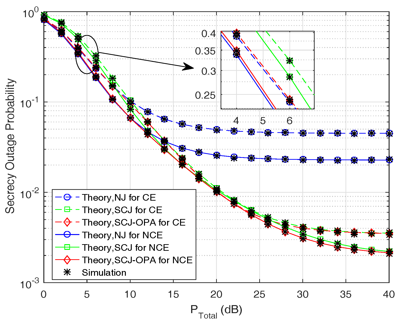
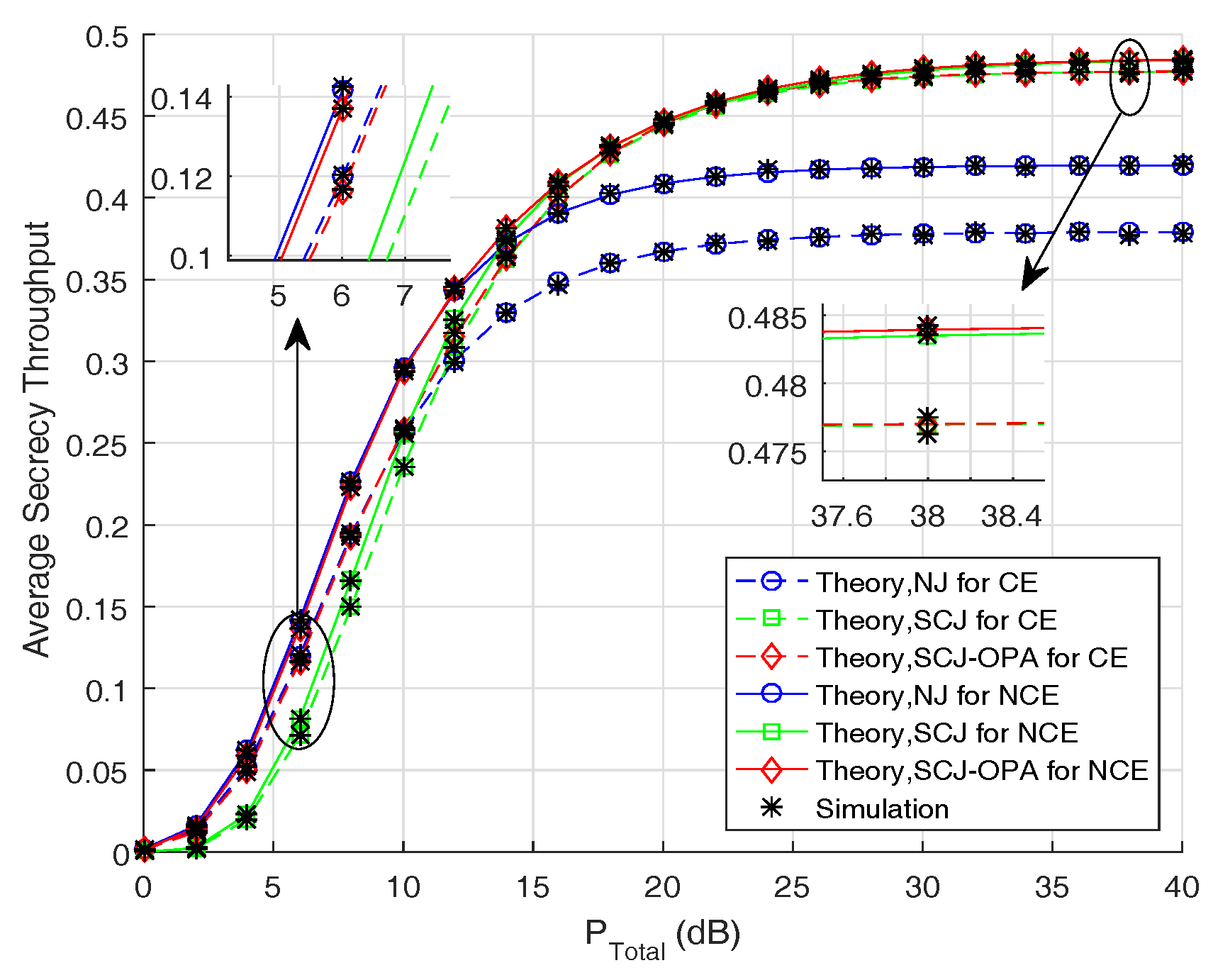
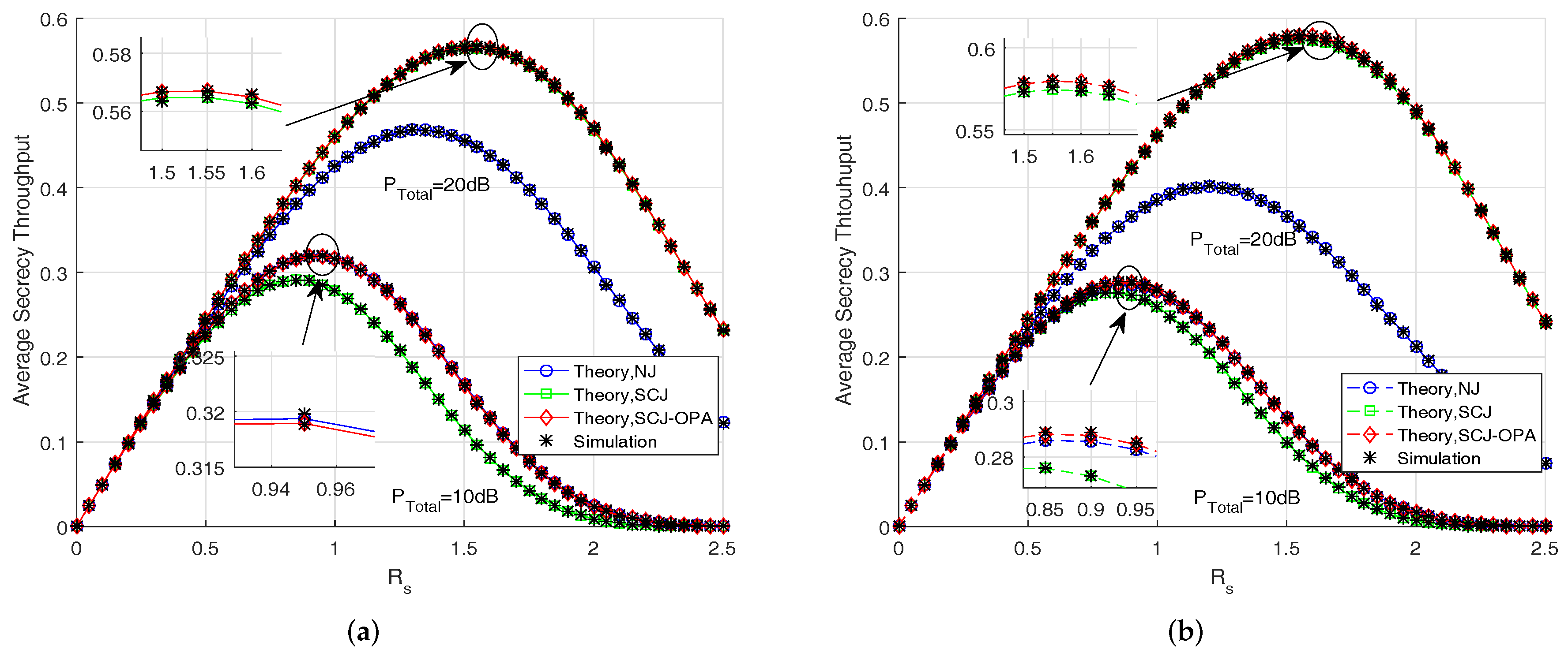
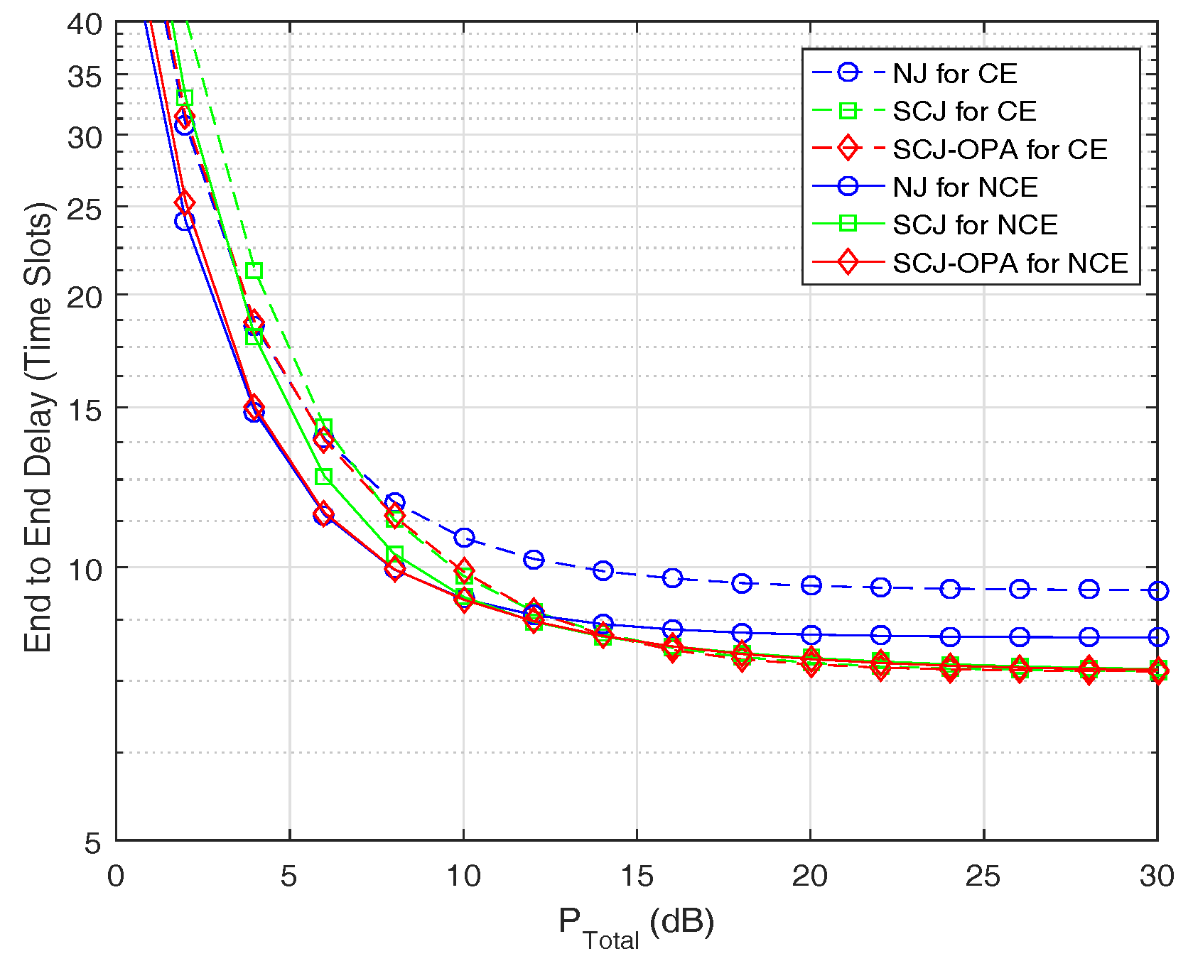
In this section, Monte-Carlo simulation results are presented to validate the theoretical analysis derived in the previous sections for the three transmission schemes. Without loss of generality, the normalized distance is set as follows: d S R = d R D = 1 , d S E = d R E = 2 . The path loss factor κ is set to be 3. From the figures, the theoretical curves are in exact agreement with the simulation results, which verifies the accuracy of our theoretical analysis.
Figure 2 illustrates the secrecy outage probability versus the total transmit power budget P T o t a l for the three proposed transmission schemes. As shown in Figure 2, the secrecy outage probability decreases with the increase of P T o t a l until a secrecy outage performance floor occurs at high transmit power. This is intuitive since both capacities of the main and wiretap channels improve with the increase of the transmit power. Furthermore, we observe that, in both the NCE and CE scenarios, the NJ scheme outperforms the SCJ scheme at the low total transmit power, while the opposite holds in the high total transmit power. For the SCJ-OPA scheme, almost the same performance as the NJ scheme can be obtained at the low transmit power, and, when P T o t a l is large, a similar performance as the SCJ scheme can also be achieved, which indicates that the SCJ-OPA scheme covers the shortages of the NJ and SCJ schemes exactly. In addition, it is worth noting that the secrecy performance of the CE scenario is worse than that of the NCE scenario under the same conditions, which is because that the MRC scheme utilized by the CE mode can enhance the ability of eavesdropping.
Figure 3 plots the average secrecy throughput of the three proposed transmission schemes versus the total transmit power budget P T o t a l . It is observed that the average secrecy throughput increases until it converges to a fixed value with the increase of the total transmit power. In addition, we further observe that the NJ and SCJ-OPA schemes outperforms the SCJ scheme in terms of the average secrecy throughput when P T o t a l is not large. At the high P T o t a l , the SCJ and SCJ-OPA schemes achieve better performance than the NJ scheme. In other words, utilizing the SCJ-OPA scheme can improve the secrecy performance of the considered system, especially when the total power is small or large.
Figure 4 investigates the impact of the secrecy rate R s on the average secrecy throughput for the NCE and CE scenarios, respectively. From these figures, we find that, for both NCE and CE scenarios, the average secrecy throughput first increases with the increase of R s and then decreases when R s increases beyond a certain value, which demonstrates the accuracy of the analysis in Section 4.2. Besides, it can be observed that when the total transmit power is small, i.e., P T o t a l = 10 dB, the SCJ-OPA scheme obtains a similar average secrecy throughput as the NJ scheme, which are both better than the SCJ scheme. On the other hand, when the total transmit power is large, i.e., P T o t a l = 20 dB, the SCJ-OPA and SCJ schemes are superior to the NJ scheme, which is consistent with the previous analysis and simulation.
Figure 5 presents the end-to-end delay for the three proposed transmission schemes versus the total transmit power budget P T o t a l . As shown in Figure 5, the end-to-end delay is significantly decreased as the P T o t a l increases in both the NCE and CE scenarios. Similarly, when the P T o t a l increases beyond a certain value, the end-to-end delay remains unchanged. That is to say, a performance floor occurs. This is because the secrecy outage probability tends to a fixed value at this moment. Furthermore, we can also observe that the SCJ-OPA scheme achieves better performance in terms of the end-to-end delay than the other two schemes across the entire transmit power range of interest, which indicates the advantage of the SCJ-OPA scheme.
Figure 6 plots the secrecy outage probability versus the buffer size L for the three proposed transmission schemes under the NCE and CE scenarios, respectively. As can be readily observed, as the buffer size increases, the achieved performance approaches the performance floor. Specifically, for both NCE and CE scenarios, the NJ and SCJ-OPA schemes outperform the SCJ scheme when P T o t a l is small. On the contrary, the SCJ and SCJ-OPA schemes are superior to the NJ scheme at the condition of the high transmit power, which matches the simulation above.
Figure 7 shows the impact of the power allocation factor α on the secrecy outage probability for the SCJ-OPA scheme. The curves shown in Figure 7 are calculated by using the grid-search or the straightforward search methods. It is clearly seen that the optimal power allocation factor is decreased with the increase of P T o t a l . That is to say, more power is allocated to transmit the useful information at the source sensor when P T o t a l is not large. This is because, when α is too small, only few packets can be sent from the source sensor to relay sensors in the first hop. Thereby, not enough data packets can be forwarded to the controller. Even if the jamming power is large in the second hop, it cannot improve the secrecy performance of the whole network. On the other hand, with the increase of P T o t a l , the dominant factor that affects the secrecy performance of the considered system changes from the information transmit power to the jamming transmit power at the source sensor, which is the exact reason the optimal power allocation factor becomes smaller gradually.

6. Conclusions

In this paper, we propose three secure transmission schemes for buffer-aided relay networks in IoT. To take full advantage of buffer-aided relay, the max-link relay selection policy is adopted to enhance the secrecy performance by selecting the main link with the best rate. Furthermore, for each schemes, we also derive the exact expressions of the secrecy outage probability, the average secrecy throughput and the end-to-end delay in closed-form by utilizing the Markov chain theory under both the NCE and CE scenarios, respectively, which provides an effective way to evaluate the secrecy performance of each proposed scheme. Our numerical results indicate that, when the total power P T o t a l is small, the performance achieved by the SCJ-OPA scheme is similar to that of the NJ scheme. On the other hand, the SCJ-OPA scheme can also achieve almost identical performance as the SCJ scheme when P T o t a l is high. In other words, the SCJ-OPA scheme achieves better performance across the whole transmit power range of interest than the other two schemes, which is because the factor α can be dynamically allocated under different total transmit power. These results could be useful in the design of buffer-aided relay IoT networks under multiple eavesdroppers scenarios.

Author Contributions

C.W. and W.Y. conceived the model; C.W. performed the simulation results and wrote the paper; and W.Y., Y.C. provided some suggestions and revised the paper.

Funding

This work was supported by the National Natural Science Foundation of China under Grant Nos. 61771487 and 61371122.

Conflicts of Interest

The authors declare no conflict of interest.

Appendix A

Let us define X 1 = h S R M 1 , n 2 and Y 1 = max 1 k K h S E k 2 , according to the order statistic, the CDF of γ E 1 N J under the NCE scenario can be expressed as
F γ E 1 N J x = Pr 1 + P S 1 X 1 1 + P S 1 Y 1 < x = 0 F X 1 x 1 P S 1 + x y f Y 1 y d y .
According to the relay selection policy and the analysis above, the CDF of X 1 and the PDF of Y 1 are, respectively, expressed as
F X 1 x = 1 e λ S R x M 1 , n ,
f Y 1 y = K λ S E 1 e λ S E y K 1 e λ S E y .
Then, substituting Equations (A2) and (A3) into Equation (A1) yields the desired result shown in Theorem 1 by using the binomial theorem [43].

Appendix B

Assuming Y 2 = h S E 2 , the PDF of Y 2 can be presented as [44]
f Y 2 y = λ S E K y K 1 e λ S E y K 1 ! .
Following the similar analysis as Equation (A1), we can derive the CDF of γ E 1 N J under the CE scenario, which can be expressed as
F γ E 1 N J x = 0 F X 1 x 1 P S 1 + x y f Y 2 y d y .
To this end, substituting Equations (A2) and (A4) into Equation (A5), the CDF of γ E 1 N J under the CE scenario can be obtained as Equation (23) after some simple manipulations.

Appendix C

We first define Z 1 = max 1 k K P R 2 h R * E k 2 1 + P J 2 h J E k 2 , and the CDF of Z 1 can be expressed as
F Z 1 z = Pr max 1 k K P R 2 h R * E k 2 1 + P J 2 h J E k 2 < z = K Pr P R 2 h R * E k 2 1 + P J 2 h J E k 2 < z .
In view of the selection of a relay sensor that is independent of the eavesdroppers’ channel, we have the PDF of h R * E k 2 and h J E k 2 as follows:
f h R * E k 2 x = λ R E e λ R E x ,
and
f h J E k 2 x = λ J E e λ J E x .
By substituting Equations (A7) and (A8) into Equation (A6), the CDF of Z 1 can be easily obtained, which is given by
F Z 1 z = 1 P R 2 λ J E P R 2 λ J E + P J 2 λ R E z e λ R E z P R 2 K .
Next, we can derive the PDF of Z 1 by taking the derivative of F Z 1 z with respect z. We also denote X 2 = h R M 2 , n D 2 and the CDF of X 2 can be easily derived by making a substitution of some parameters. Following a similar approach, the CDF of γ E 2 S C J under the NCE scenario can be given by
F γ E 2 S C J x = Pr 1 + X 2 1 + Z 1 < x = 0 F X 2 x z + x 1 f z 1 z d z .
Substituting the CDF of X 2 and the PDF of Z 1 into Equation (A10), and denoting β = λ J E P R 2 λ R E P J 2 , μ t = λ R D s x + λ R E t + 1 P R 2 , the CDF of γ E 2 S C J can be further expressed as
F γ E 2 S C J x = K s = 0 M 2 , n t = 0 K 1 M 2 , n s K 1 t 1 s + t β t × e λ R D s x 1 P R 2 λ J E P J 2 0 e μ t y d y y + β t + 1 I 1 t + β 0 e μ t y d y y + β t + 2 I 2 t .
For item I 1 t , there are two cases to consider, i.e., t = 0 and t > 0 . We can obtain the corresponding terms for two cases according to the equalities [40] (eq. (3.352.4)) and [40] (eq. (3.353.2)), respectively. Similarly, the item I 2 t can be easily derived when we utilize [40] (eq. (3.353.2)) to solve the corresponding integral. Finally, the desired results in Theorem 4 can be easily obtained after some mathematical manipulations.

Appendix D

Denoting Y 3 = h R * E 2 and Z 2 = h J E 2 , the CDF of γ E 2 S C J under the CE scenario can be given by
F γ E 2 S C J x = Pr 1 + P R 2 X 2 1 + P R 2 Y 3 1 + P J 2 Z 2 < x = 0 0 F X 2 x 1 P R 2 + x y 1 + P J 2 z f Y 3 y d y f Z 2 z d z .
By invoking the PDF of Y 3 and Z 2 and the CDF of X 2 into Equation (A12), we can obtain the expression as follows:
F γ E 2 S C J x = s = 0 M 2 , n M 2 , n s 1 s e λ R D s x 1 P R 2 × 0 0 λ R E K y K 1 K 1 ! e λ R E + λ R D s x 1 + P J 2 z y d y Λ λ J E K z K 1 e λ J E z K 1 ! d z Φ .
Now, by utilizing [40] (eq. (3.351.3)) and the binomial theorem, we have
Λ = 1 θ z + ω K = t = 0 K K t 1 t θ z + ω t ,
where θ = λ R D s x P J 2 λ R E and ω = θ + 1 P J 2 for the analysis tractable. Hence, Φ can be further written as
Φ = t = 0 K K t θ t λ J E K K 1 ! 0 z K 1 e λ J E z d z z + ω t Φ 2 .
Obviously, to obtain Φ , we have to calculate Φ 2 first. For the item Φ 2 , there are also two cases to consider, i.e., t = 0 and t > 0 . For t = 0 , with the help of [40] (eq. (3.351.3)), we have Φ 2 = K 1 ! λ J E K , which yields Φ = 1 . On the other hand, for t > 0 , by changing variable z + ω = ρ and using the binomial theorem, we have
Φ 2 = e ω λ J E l = 0 K 1 K 1 l ω K 1 l ω ρ l t e λ J E ρ d ρ Φ 1 .
By utilizing [40] (eq. (3.351.2)), [40] (eq. (3.352.2)) and [40] (eq. (3.353.1)), the item Φ 1 as t > 0 can be derived, as shown in Equation (32). Finally, the desired result in Theorem 5 can be derived by pulling everything together.

References

  1. Xu, L.; He, W.; Li, S. Internet of things in industries: A survey. IEEE Trans. Ind. Inform. 2014, 10, 2233–2243. [Google Scholar] [CrossRef]
  2. Mukherjee, A. Physical-layer security in the Internet of things: Sensing and communication confidentiality under resource constraints. Proc. IEEE 2015, 103, 1747–1761. [Google Scholar] [CrossRef]
  3. Xu, Q.; Ren, P.; Song, H.; Du, Q. Security enhancement for IoT communications exposed to eavesdroppers with uncertain locations. IEEE Access 2016, 4, 2840–2853. [Google Scholar] [CrossRef]
  4. Chen, Y.; Han, F.; Yang, Y.; Ma, H.; Han, Y.; Jiang, C.; Lai, H.; Claffey, D.; Safar, Z.; Liu, K. Time-reversal wireless paradigm for green Internet of things: An overview. IEEE Internet Things J. 2014, 1, 81–98. [Google Scholar] [CrossRef]
  5. Lyu, B.; Yang, Z.; Guo, H.; Tian, F.; Gui, G. Relay cooperation enhanced backscatter communication for Internet-of-things. IEEE Internet Things J. 2019, 6, 2860–2871. [Google Scholar] [CrossRef]
  6. Ji, B.; Li, Y.; Zhou, B.; Li, C.; Song, K.; Wen, H. Performance analysis of UAV relay assisted IoT communication network enhanced with energy harvesting. IEEE Access 2019, 7, 38738–38747. [Google Scholar] [CrossRef]
  7. Chen, G.; Coon, J.; Mondal, A.; Allen, B.; Chambers, J. Performance analysis for multi-hop full-duplex IoT networks subject to poisson distributed interferers. IEEE Internet Things J. 2019, 6, 3467–3479. [Google Scholar] [CrossRef]
  8. Massri, K.; Vitaletti, A.; Vernata, A.; Chatzigiannakis, I. Routing protocols for delay tolerant networks: A reference architecture and a thorough quantitative evaluation. J. Sens. Actuator Netw. 2016, 5, 6. [Google Scholar] [CrossRef]
  9. Michalopoulos, D.; Karagiannidis, G. Performance analysis of single relay selection in Rayleigh fading. IEEE Trans. Wirel. Commun. 2008, 7, 3718–3724. [Google Scholar] [CrossRef]
  10. Xia, B.; Fan, Y.; Thompson, J.; Poor, H. Buffering in a three-node relay network. IEEE Trans. Wirel. Commun. 2008, 7, 4492–4496. [Google Scholar] [CrossRef]
  11. Zlatanov, N.; Schober, R.; Popovski, P. Buffer-aided relaying with adaptive link selection. IEEE J. Sel. Areas Commun. 2013, 31, 1530–1542. [Google Scholar] [CrossRef]
  12. Ikhlef, A.; Michalopoulos, D.; Schober, R. Max-max relay selection for relays with buffers. IEEE Trans. Wirel. Commun. 2012, 11, 1124–1135. [Google Scholar] [CrossRef]
  13. Krikidis, I.; Charalambous, T.; Thompson, J. Buffer-aided relay selection for cooperative diversity systems without delay constraints. IEEE Trans. Wirel. Commun. 2012, 11, 1957–1967. [Google Scholar] [CrossRef]
  14. Nasir, H.; Javaid, N.; Raza, W.; Guizani, M.; Alrajeh, N.; Alabed, M. Virtual-link relay selection scheme for buffer-aided IoT based cooperative relay networks. IEEE Access 2018, 6, 74648–74659. [Google Scholar] [CrossRef]
  15. Shabbir, G.; Ahmad, J.; Raza, W.; Amin, Y.; Akram, A.; Loo, J.; Tenhunen, H. Buffer-aided successive relay selection scheme for energy harvesting IoT networks. IEEE Access 2019, 7, 36246–36258. [Google Scholar] [CrossRef]
  16. Alkhawatrah, M.; Gong, Y.; Chen, G.; Lambotharan, S.; Chambers, J. Buffer-aided relay selection for cooperative NOMA in the Internet of things. IEEE Internet Things J. 2019, 6, 5722–5731. [Google Scholar] [CrossRef]
  17. Mukherjee, A.; Fakoorian, S.; Huang, J.; Swindlehurst, A. Principles of physical layer security in multiuser wireless networks: A survey. IEEE Commun. Surv. Tutor. 2014, 16, 1550–1573. [Google Scholar] [CrossRef]
  18. Zou, Y.; Zhu, J.; Wang, X.; Hanzo, L. A survey on wireless security: Technical challenges, recent advances, and future trends. Proc. IEEE 2016, 104, 1727–1765. [Google Scholar] [CrossRef]
  19. Bloch, M.; Barros, J.; Rodrigues, M.; Mclaughlin, S. Wireless information-theoretic security. IEEE Trans. Inf. Theory 2008, 54, 2515–2534. [Google Scholar] [CrossRef]
  20. Liang, Y.; Poor, H.; Shamai, S. Secure communication over fading channels. IEEE Trans. Inf. Theory 2008, 54, 2470–2492. [Google Scholar] [CrossRef]
  21. Nan, Y.; Wang, L.; Geraci, G.; Elkashlan, M.; Yuan, J.; Renzo, M. Safeguarding 5G wireless communication networks using physical layer security. IEEE Commun. Mag. 2015, 53, 20–27. [Google Scholar]
  22. Zou, Y.; Zhu, J.; Wang, X.; Leung, V. Improving physical-layer security in wireless communications using diversity techniques. IEEE Netw. 2015, 29, 42–48. [Google Scholar] [CrossRef] [Green Version]
  23. Zhang, Y.; Shen, Y.; Wang, H.; Yong, J.; Jiang, X. On secure wireless communications for IoT under eavesdropper collusion. IEEE Trans. Autom. Sci. Eng. 2016, 13, 1281–1293. [Google Scholar] [CrossRef]
  24. Chen, D.; Yang, W.; Hu, J.; Cai, Y.; Tang, X. Energy-efficient secure transmission design for the Internet of things with an untrusted relay. IEEE Access 2018, 6, 11862–11870. [Google Scholar] [CrossRef]
  25. Hu, J.; Yang, N.; Cai, Y. Secure downlink transmission in the Internet of things: How many antennas are needed? IEEE J. Sel. Areas Commun. 2018, 36, 1622–1634. [Google Scholar] [CrossRef]
  26. Huang, P.; Hao, Y.; Lv, T.; Xing, J.; Yang, J.; Mathiopoulos, P. Secure beamforming design in relay-assisted Internet of things. IEEE Internet Things J. 2019, 6, 6453–6464. [Google Scholar] [CrossRef]
  27. Chen, G.; Tian, Z.; Gong, Y.; Chen, Z.; Chambers, J. Max-ratio relay selection in secure buffer-aided cooperative wireless networks. IEEE Trans. Inf. Forensics Secur. 2014, 9, 719–729. [Google Scholar] [CrossRef]
  28. Tang, X.; Cai, Y.; Huang, Y.; Duong, T.; Yang, W.; Yang, W. Secrecy outage analysis of buffer-aided cooperative MIMO relaying systems. IEEE Trans. Veh. Technol. 2018, 67, 2035–2048. [Google Scholar] [CrossRef]
  29. Sun, A.; Liang, T.; Zhang, Y. Performance analysis of secure buffer-aided cognitive radio network. In Proceedings of the 2015 4th IEEE/CIC International Conference on Communications in China (ICCC), Shenzhen, China, 2–4 November 2015; pp. 1–4. [Google Scholar]
  30. Bletsas, A.; Shin, H.; Win, M. Cooperative communications with outage-optimal opportunistic relaying. IEEE Trans. Wirel. Commun. 2007, 6, 3450–3460. [Google Scholar] [CrossRef]
  31. Chatzigiannakis, I.; Kinalis, A.; Nikoletseas, S. Efficient data propagation strategies in wireless sensor networks using a single mobile sink. Comput. Commun. 2008, 31, 896–914. [Google Scholar] [CrossRef]
  32. Chatzigiannakis, I.; Kinalis, A.; Nikoletseas, S. Fault-tolerant and efficient data propagation in wireless sensor networks using local, additional network information. J. Parallel Distrib. Comput. 2007, 67, 456–473. [Google Scholar] [CrossRef]
  33. Zheng, T.; Wang, H.; Yuan, J.; Towsley, D.; Lee, M. Multi-antenna transmission with artificial noise against randomly distributed eavesdroppers. IEEE Trans. Commun. 2015, 63, 4347–4362. [Google Scholar] [CrossRef]
  34. Zhou, X.; Ganti, R.; Andrews, J. Secure wireless network connectivity with multi-antenna transmission. IEEE Trans. Wirel. Commun. 2011, 10, 425–430. [Google Scholar] [CrossRef]
  35. Huang, Y.; Zhang, P.; Wu, Q.; Wang, J. Secrecy performance of wireless powered communication networks with multiple eavesdroppers and outdated CSI. IEEE Access 2018, 6, 33774–33788. [Google Scholar] [CrossRef]
  36. Gopala, P.; Lai, L.; Gamal, H. On the secrecy capacity of fading channels. IEEE Trans. Inf. Theory 2008, 54, 4687–4698. [Google Scholar] [CrossRef]
  37. Oggier, F.; Hassibi, B. The secrecy capacity of the MIMO wiretap channel. IEEE Trans. Inf. Theory 2011, 57, 4961–4972. [Google Scholar] [CrossRef]
  38. Chatzigiannakis, I.; Nikoletseas, S. Design and analysis of an efficient communication strategy for hierarchical and highly changing ad-hoc mobile networks. Mob. Netw. Appl. 2004, 9, 319–332. [Google Scholar] [CrossRef]
  39. Chatzigiannakis, I.; Nikoletseas, S.; Spirakis, P. On the average and worst-case efficiency of some new distributed communication and control algorithms for ad-hoc mobile networks. In Proceedings of the 1st ACM Int’l Workshop on Principles of Mobile Computing (POMC’01), Newport, RI, USA, August 2001; pp. 1–19. [Google Scholar]
  40. Gradshteyn, I.; Ryzhik, I. Table of Integrals, Series, and Products; Publishing House: San Diego, CA, USA, 2007. [Google Scholar]
  41. Chen, G.; Gong, Y.; Xiao, P.; Tafazolli, R. Dual antenna selection in self-backhauling multiple small cell networks. IEEE Commun. Lett. 2016, 20, 1611–1614. [Google Scholar] [CrossRef]
  42. Tian, Z.; Gong, Y.; Chen, G.; Chambers, J. Buffer-aided relay selection with reduced packet delay in cooperative networks. IEEE Trans. Veh. Technol. 2017, 66, 2567–2575. [Google Scholar] [CrossRef]
  43. Coolidge, J.L. The Story of the Binomial Theorem. Am. Math. Mon. 1949, 23, 147–157. [Google Scholar] [CrossRef]
  44. Afana, A.; Asghari, V.; Ghrayeb, A.; Affes, S. Cooperative relaying in spectrum-sharing systems with beamforming and interference constraints. In Proceedings of the 2012 IEEE 13th International Workshop on Signal Processing Advances in Wireless Communications (SPAWC), Cesme, Turkey, 17–20 June 2012; pp. 429–433. [Google Scholar]
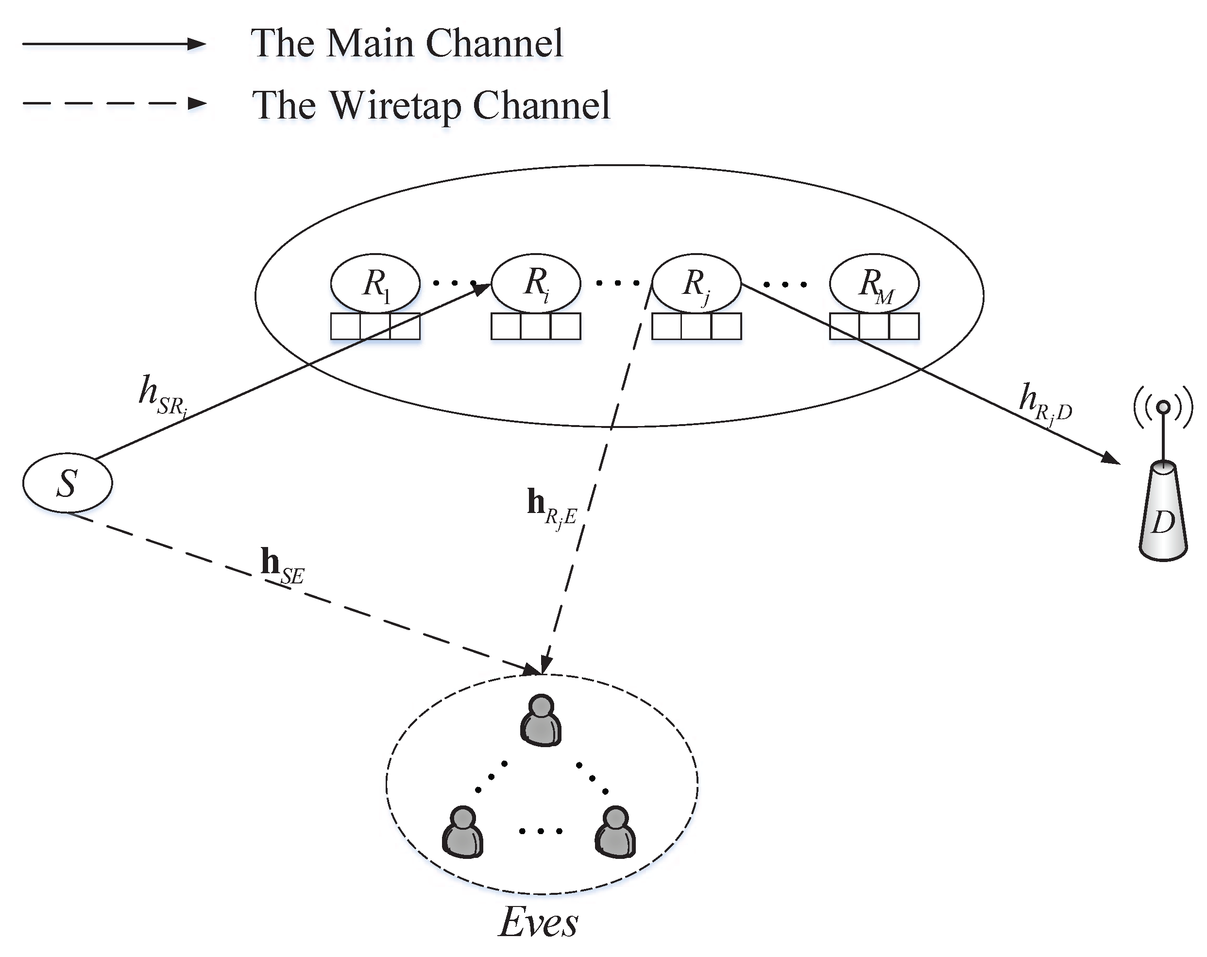
Figure 1. System Model.
Applsci 09 04506 g001
Figure 2. Secrecy outage probability vs. the total transmit power budget P T o t a l for the three proposed transmission schemes when R s = 0.6 (bit/s/Hz), M = 3, L = 2, K = 2 .
Applsci 09 04506 g002
Figure 3. Average Secrecy throughput vs. the total transmit power budget P T o t a l for the three proposed transmission schemes when R s = 1 (bit/s/Hz), M = L = 2, K = 2 .
Applsci 09 04506 g003
Figure 4. Average Secrecy throughput vs. the secrecy rate R s for the three proposed transmission schemes under the NCE (a) and CE (b) scenarios when M = 2, L = 3, K = 2 , P T o t a l = 10, 20 dB.
Applsci 09 04506 g004
Figure 5. End to end delay vs. the total transmit power budget P T o t a l for the three proposed transmission schemes when R s = 0.6 (bit/s/Hz), M = L = 2, K = 3.
Applsci 09 04506 g005
Figure 6. Secrecy outage probability vs. the buffer size L for the three proposed transmission schemes under the NCE (a) and CE (b) scenarios when R s = 0.5 (bit/s/Hz), M = 2, K = 3, P T o t a l = 5, 15 dB.
Applsci 09 04506 g006
Figure 7. Secrecy outage probability vs. the power allocation factor α for the SCJ-OPA scheme under the NCE and CE scenarios when R s = 0.5 (bit/s/Hz), M = L = 2, K = 2, and P T o t a l = 12, 20, 30 dB.
Applsci 09 04506 g007
Table 1. List of the main notations and parameters.
SymbolDescriptionSymbolDescription
MNumber of relay sensors · T The transpose operation
R m The m-th relay sensor M 1 , n The number of available links in the first hop
KNumber of eavesdroppers M 2 , n The number of available links in the second hop
E k The k-th eavesdropper α The power allocation factor
LBuffer size P o u t The overall secrecy outage probability
h a b The channel coefficient of link a b P o u t , n The secrecy outage probability at state s n
h a b The channel vector of link a b π The stationary probability vector
E [ · ] The expectation operation π n The stationary probability vector at state s n
d a b The distance between a and b R s The predefined secrecy rate
κ The path loss factor γ t h The secrecy outage threshold
C a b The achievable secrecy rate of link a b NThe number of all the buffer states
σ 2 The variance of AWGN A The state transition matrix
P S The maximum transmit power of S A v , n The (v,n)th entry of A
P R The maximum transmit power of relay sensor I The identity matrix
P T o t a l The total power Q The all-ones matrix
s n The n-th buffer state T ¯ The average secrecy throughput
φ n m The number of data packets in B m at state s n D ¯ t o t a l The average end-to-end delay
· The Euclidean or L 2 vector norm Q ¯ m The average queuing length at R m