Abstract
Carbon nanotubes (CNTs) are extensively adopted in the applications of biotechnology and biomedicine. Their interactions with cell membranes are of great importance for understanding the toxicity of CNTs and the application of drug delivery. In this paper, we use atomic molecular dynamics simulations to study the permeation and orientation of pristine and functionalized CNTs in a lipid bilayer. Pristine CNT (PCNT) can readily permeate into the membrane and reside in the hydrophobic region without specific orientation. The insertion of PCNTs into the lipid bilayer is robust and independent on the lengths of PCNTs. Due to the presence of hydroxyl groups on both ends of the functionalized CNT (FCNT), FCNT prefers to stand upright in the lipid bilayer center. Compared with PCNT, FCNT is more suitable to be a bridge connecting the inner and outer lipid membrane. The inserted CNTs have no distinct effects on membrane structure. However, they may block the ion channels. In addition, preliminary explorations on the transport properties of CNTs show that the small hydrophobic molecule carbon dioxide can enter both PCNT and FCNT hollow channels. However, hydrophilic molecule urea is prone to penetrate the PCNT but finds it difficult to enter the FCNT. These results may provide new insights into the internalization of CNT in the lipid membrane and the transport properties of CNTs when embedded therein.
1. Introduction
The introduction of carbon nanoparticles into the biotechnological and biomedical fields has opened a large number of applications, such as biosensors and drug carriers [1,2,3,4,5,6,7,8]. One such kind of nanomaterial is the carbon nanotube (CNT), which can deliver peptides [6,8], proteins [4], and nucleic acids [5] to different cells. Ahead of these applications, understanding the interactions between CNTs and phospholipid membranes is fundamentally essential for avoiding its adverse effects, since CNTs may be toxic. Therefore, present studies are mainly focused on cytotoxicity and its interactions with cell membranes [9,10,11,12]. For example, experiments have demonstrated that CNTs induce oxidative damage to lipids in lung membranes [13] and the formation of reactive oxygen species in vivo and in vitro [14,15]. CNTs have also been found to enter both animal and plant cells [16,17], but the internalization mechanism is still not clear. Two very recent works show that short CNTs can transport water, protons, and small ions after the spontaneous insertion into the live cell membranes [18]. Meanwhile, the embedded CNTs possess ion selectivity that can be tuned by pH values and ion concentrations [19]. These reports demonstrate that CNTs in the membrane can transport small molecules through their hollow channels [20].
In recent years, molecular dynamics (MD) simulation has been employed to explore the interactions between carbon nanoparticles and lipid membranes [21,22,23,24,25]. Particularly, how CNTs land on, bind to, and translocate through cell membrane are systematically studied by MD simulations [26,27,28]. For example, Wallace and Sansom performed steered MD with a coarse-grained model to simulate the penetration of the dipalmitoylphosphatidylcholine (DPPC) bilayer by CNTs, and they observed that lipids were extracted from the bilayer and blocked the tube [23]. However, the penetration was not spontaneous but exerted by an external force to pull the nanotube through the bilayer. Pathasarathi et al. reported the presence of CNTs in the bilayer reduced the mobility of lipids and perturbed the structure of interfacial water, using all-atom MD simulations [24]. It should be noted that the CNTs are initially embedded in the lipid bilayer. Kraszewski et al. performed MD simulations to explore the internalization of functionalized CNTs (FCNTs) into a model lipid bilayer as a function of their length [26,27]. They found the hydrophobicity was one of the key factors responsible for the insertion process. However, experiments conducted by Lacerda et al. showed that electrostatic interactions between the hydrophilic and charged functional moieties of FCNTs and the polar headgroups of the lipid membranes were the major contributors to the insertion process [28]. Obviously, they are contradictory.
In this work, we first repeated the simulations on the interactions between CNTs and lipid membranes. Then, we studied the effects of CNTs on membrane structure and membrane protein. Finally, we performed MD simulations to investigate the transport properties of CNTs when embedded in the bilayer center. We observed that pristine CNT (PCNT) could readily enter the membrane and stay therein without specific orientation. When functionalized CNT (FCNT) was embedded in the membrane, FCNT preferred to locate vertically. CNTs in the lipid bilayer may block membrane proteins. However, CNTs can act as artificial channels to transport water, ions, and small molecules. Taking carbon dioxide (CO2) and urea as model small molecules, we found CO2 could enter both PCNT and FCNT hollow channels because of their hydrophobic interior, while urea molecules were found it much difficult to fill the FCNT.
2. Computational Methods
The simulation system consisted of a fully hydrated lipid bilayer, one PCNT or one FCNT, and 2 mol% carbon dioxide (CO2) or urea molecules. Here, mole percent is defined as the number of CO2/urea molecules divided by the sum of CO2/urea and water molecules. CO2 and urea are two common metabolites, on behalf of small hydrophobic and hydrophilic molecules, and suitable for transport through CNT hollow channels. The hydrated bilayer developed by Tieleman and Berendsen was composed of 128 dipalmitoylphosphatidylcholine (DPPC) lipids and about 5000 water molecules. We constructed the pristine and functionalized armchair type (6,6) and (7,7) CNTs, which were about 3.6 nm in length, close to the thickness of the membrane. The FCNT was modeled by attaching 12 hydroxyl groups and 12 hydrogen atoms to the terminal carbon atoms on the pristine one.
The force field parameters for DPPC lipids and CNTs were taken from Berger et al. and Hummer et al., respectively [29,30]. The topologies of CO2 and urea were created by the PRODRG server, based on the GROMOS53a6 force field. However, the partial charges assigned by PRODRG were found to result in an incorrect water solubility and unrealistic partitioning between water and membrane [31]. We, therefore, resorted to Mulliken partial charges obtained after density functional theory (DFT) calculations at the B3LYP/6-31G (d,p) level. The vdW parameters for CO2 and urea were included with GROMACS itself. Water was represented by the SPC model [32]. The carbon atoms in PCNT were treated as uncharged Lennard–Jones (LJ) spheres with a cross-section of σcc = 0.34 nm and a depth of the potential well of εcc = 0.36 kJ/mol. The carbon, oxygen, and hydrogen atoms in C—O—H were assigned partial charges of +0.5e, −0.8e, and +0.3e, the same as [23]. The bonded and non-bonded parameters of C—O—H were adopted from the GROMOS 53a6 force field [33].
All simulations were performed under the isothermal-isobaric (NPT) ensemble by using the Gromacs package 4.5.6 [34,35]. Periodic boundary conditions were employed in all directions. The vdW interactions were treated with a smooth cutoff at a distance of 1 nm, whereas the particle-mesh Ewald method was used to calculate the long-range electrostatic interactions [36,37]. The temperature was kept stable at 323 K using the V-rescale thermostat, and the pressure was controlled semi-isotropically by a Berendsen barostat [38,39]. Bond lengths within CNT/DPPC and water molecules were constrained by the LINCS and the SETTLE algorithms, which allowed a time step of 2 fs [40,41].
The free energy of CO2 and urea molecules across the bilayer and CNT was obtained from the potential of mean force (PMF) using umbrella sampling [42]. First, we performed steered MD simulations to pull the molecule from the aqueous phase to the center of mass of the membrane or CNT [43]. Then, 35 windows were generated along the reaction coordinate (z-direction). The z coordinates of the center of mass (COM) distance between the molecule and membrane or CNT in each window differed by about 0.1 nm to ensure sufficient sampling. Each window was run for 10 ns, and the last 5 ns data were collected for sampling. In such cases, a simulation was biased by a harmonic potential with a spring of 1000 kJ mol−1 nm−2. Finally, the PMF profile was depicted by the weighted histogram analysis method (WHAM) [44].
3. Results and Discussion
3.1. Simulations Results of PCNT
Figure 1 shows the entering of PCNT from the aqueous phase into the lipid bilayer. Generally, the process was composed of two stages: (1) fast adsorption of PCNT at the lipid-water interface in an orientation parallel to the membrane plane, followed by (2) spontaneous tilting of the tube to insert the membrane. In detail, we employed the center of mass (COM) distance in the z-direction (denoted as dz) between PCNT and the membrane to depict this entry (Figure 1B). The orientation of PCNT out and in the membrane is monitored by the tilt angle (α), which is defined as the included angle between the central axis of PCNT and the membrane plane (xy-plane). It is observed that PCNT initially diffuses quickly toward the bilayer. Correspondingly, dz drops fast from 4 nm to 2.5 nm in the first 3 ns. Then PCNT lies flat (α is close to 90°) at the hydrophilic interface until t = 24 ns. However, at t = 25 ns, one end of the PCNT begins to slant and insert the membrane (see snapshots at t = 25 ns), and then the whole PCNT is quickly pulled into the membrane in the following 2 ns in a tilted position (see snapshots at t = 26 and 27 ns). Accordingly, dz plummets from 2.5 to 0.5 nm, and α drops from 90° to 45°. After entering the membrane, the CNT just floats therein with a tilted orientation (snapshot at t = 100 ns). And the membrane is kept intact without any rupture.
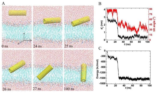
Figure 1.
A typical trajectory of pristine carbon nanotubes (PCNT) entering the membrane. (A) Snapshots at critical times. (B,C) Time evolutions of the center of mass (COM) distance in the z-direction, the tilt angle, and the interaction energy between PCNT and membrane.
Similar to the permeation of fullerene and graphene in the lipid membrane, the fast insertion of PCNT is driven by the strong dispersion interactions between PCNT and lipid tails. We, therefore, calculated the interaction energy of PCNT with the bilayer (Figure 1C). Here, the energy is defined as the vdW interaction between the CNT and membrane. The energy curve exhibited the same trend as that of dz (see Figure 1b,c), implying that the translocation of PCNT from the water to the membrane is driven by this interaction. The energy difference of CNT in and out of the bilayer reached about 1200 kJ/mol. It is clear that the huge fall in the energy makes PCNT adsorb fast into the lipid bilayer.
The location and orientation of PCNT in the membrane can be characterized by the horizontal COM distance between PCNT and membrane (marked as dxy) and the tilt angle α. As shown in Figure 2A, the curves of dxy fluctuate dramatically in both systems, indicating that PCNT can move freely in the membrane. Interestingly, it is found that PCNT exhibits different orientations at the end of each simulation, namely, vertical (Figure 1, snapshot at t=100ns), horizontal (Figure S1A, snapshot at t = 100 ns) and tilted (Figure S1B, snapshot at t = 100 ns). We, therefore, compared the interaction energy between CNT and bilayer at different tilt angles (0°, 15°, 30°, 45°, 60°, 75°, and 90°), as shown in Figure 2C. The energy at each tilt angle shows little difference, which is less than 3% between the strongest interaction (-1573 kJ/mol at α = 0°) and the weakest one (-1529 kJ/mol at α = 45°), implying that PCNT resided in the bilayer with no specific orientations. We repeated the simulations with PCNT embedded in the bilayer center horizontally and vertically and obtained similar results, though PCNT may be confined at local minima (see Supplementary Material, Figure S1).
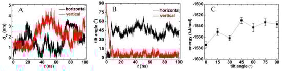
Figure 2.
The location (A) and orientation (B) of PCNT in the membrane, and (C) the interaction energies at fixed tilt angles.
To explore the effects of CNT length on its insertion into the lipid membrane, we performed three additional independent simulations, with different lengths of PCNTs, namely, 2.4 nm, 3.6 nm, and 4.8 nm, which are shorter or close to or longer than the bilayer thickness. As shown in Figure 3, the spontaneous insertion of PCNTs in the lipid bilayer was robust, independent of the lengths of PCNTs (see snapshots at t = 100 ns). Shorter PCNTs with lengths less than the thickness of the bilayer underwent significant rotation during the insertion and preferred to reside in the bilayer center vertically (Figure 3B, D). The tilt angles fluctuated slightly at 10°. It should be pointed out that the final orientations of PCNTs were related to their initial structures. With the increasing lengths of PCNTs, the rotation became more and more difficult, as longer PCNTs were prone to be confined at local minima, similar to the simulation results of PCNT initially embedded in the bilayer center horizontally (Supplementary Material, Figure S1). That is, the PCNT always lay flat in the membrane (Figure 3F). Correspondingly, the tilt angle was kept stable at 68°.
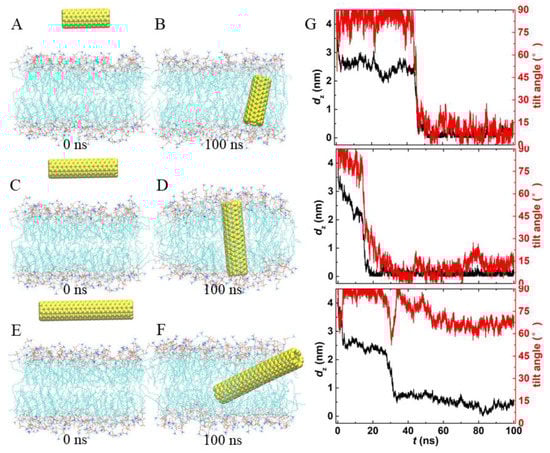
Figure 3.
Trajectories of PCNTs with different lengths entering the membrane. (A–F) The initial and final snapshots of each system. Water is not shown for clarity. (G) Time evolutions of the COM distance in the z-direction and the tilt angles of each system.
3.2. Simulation Results of FCNT
The potential applications of CNT are as nanocarriers, and CNT acts as an artificial channel connecting the inner and outer cell membranes to deliver drug molecules. However, PCNT preferred to stay in the hydrophobic region of the membrane with arbitrary orientations. We, therefore, resorted to FCNT. Initially, we embedded the FCNT vertically and horizontally in the membrane center and then released it. As shown in Figure 4A, the FCNT was kept almost perpendicular during the whole simulation, as the tilt angle was always more than 75° (Figure 4C). Interestingly, it was found that the FCNT rotated from horizontal to vertical in Figure 4B, as the tilt angle increased gradually from 0° to 70°. This rotation was driven by electrostatic interactions. Therefore, we counted the number of hydrogen bonds formed between hydroxyl groups on the ends of FCNT and lipid headgroups (see Figure 4D). In both systems, there was an average of about 5 hydrogen bonds formed between FCNT and lipid bilayer, which made them interlocked with each other, and FCNT was prone to vertical orientation. Compared with PCNT, FCNT is more suited to serve as an artificial channel to transport drug molecules.
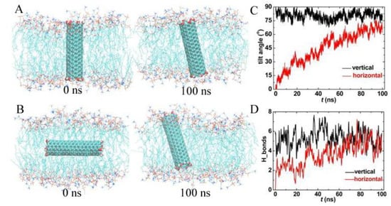
Figure 4.
Trajectories of functionalized carbon nanotubes (FCNT) located in the membrane vertically and horizontally. (A,B) Snapshots at t = 0 ns and 100 ns, (C) the tilt angle, and (D) the hydrogen bonds between FCNT and lipid bilayer.
3.3. Effects of CNTs on Membrane Structure and Membrane protein
To evaluate the effects of inserted CNTs on membrane structure, we compared the area per lipid, bilayer thickness, and lipid tail order of the membrane with or without CNTs. As shown in Figure 5A,B, the area per lipid without CNT averaged over the last 50 ns was 0.651 nm2, while they were 0.654 nm2 and 0.653 nm2 with embedded PCNT and FCNT, respectively. Because of the undulation of the membrane, the difference among them (about 0.002 nm2) can be neglected. The corresponding thicknesses of the bilayer were 3.657 ± 0.048 nm, 3.612 ± 0.064 nm, and 3.644 ± 0.056 nm, also close to each other. The main effect of CNTs on membrane structure was that the lipid tails became more ordered with the inserted CNTs, as the deuterium order parameters with CNTs were a little bigger than those of pure membrane (Figure 5C). This is because the local lipid tails around the CNTs aligned more orderly and closely.
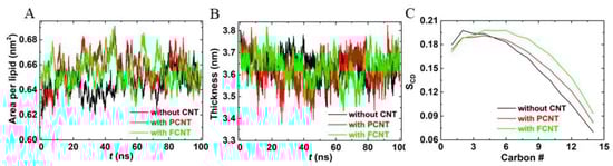
Figure 5.
The effects of carbon nanotubes (CNT) on the membrane structure compared with the pure bilayer. (A) Area per lipid, (B) the bilayer thickness, and (C) deuterium order parameter for a lipid chain.
Then, we performed particular simulations to explore how inserted CNTs interact with existing membrane proteins. A potassium channel (K+ conduction and selectivity architecture, KcsA) was selected as a model membrane protein (PDB ID: 2A9H). Initially, the protein was embedded in the phosphoethanolamine (POPE) lipid bilayer, and CNTs were positioned at the aqueous phase, as shown in Figure 6A,C, and then the CNTs were released. Interestingly, it was found that the channel of KcsA was blocked by both PCNT and FCNT (Figure 6B,D). The blockage of the potassium channel may weaken the transport of Na+, K+, and so on, which further affects the transduction of nerve signals. Fortunately, CNTs exhibit considerable potential as artificial ion channels and possess selectivity after inserting the cell membrane. That is, this problem may be solved by CNTs themselves. Figure 6E gives the time evolution of the RMSDs of the backbone of KcsA with or without CNTs. We observe that the three root-mean-square-deviation (RMSD) curves are in line with each other except for a little difference in the last 50 ns, indicating that the secondary structure of KcsA had no distinct change exerted by inserted CNTs.
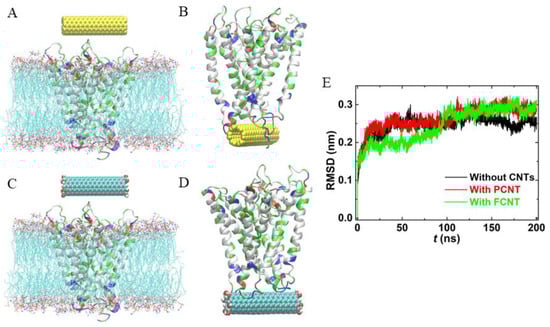
Figure 6.
The effects of CNTs on membrane protein. (A,C) The initial configurations, where water molecules are not shown for clarity. (B,D) The structures of CNT-KcsA complexes. (D) root-mean-square-deviations (RMSDs) of KcsA in the lipid bilayer with or without CNTs.
3.4. Transport of Small Molecules through PCNT
Next, we chose CO2 and urea on behalf of small hydrophobic and hydrophilic molecules to tentatively explore the transport of small molecules through CNT hollow channels. For simplicity, the PCNT was position-restrained in the bilayer center vertically. The simulation results are presented in Figure 7. As a control run, we also investigated the distribution of CO2 and urea in the lipid bilayer without CNTs. Interestingly, it was found that although CO2 molecules can readily enter the membrane, they prefer to aggregate in the PCNT hollow channel. Figure 6C shows the number of water and CO2 molecules in the PCNT as a function of simulation time. Since the PCNT interior was hydrophobic, water molecules were gradually excluded from the CNT, and CO2 molecules flow in. Correspondingly, the number of water declined from 11 to 0, while that of CO2 increased from 0 to 9. Different from CO2, hydrophilic urea molecules could not reach the membrane center spontaneously, but similarly could flow into the PCNT interior. Surprisingly, the PCNT was filled with a mixture of water and urea molecules. As shown in Figure 7D, there were approximately 4 urea and 13 water molecules in the PCNT hollow channel. These results were independent of whether the starting structures of the PCNT were empty or filled with CO2/urea (see Supplementary Material, Figure S2)
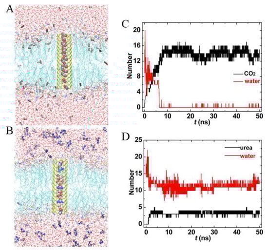
Figure 7.
The transport properties of (7,7) PCNT in the lipid bilayer. (A,B) Snapshots at t = 50 ns, only half of the tubes are shown to highlight CO2 and urea molecules in the PCNT hollow channels. (C,D) Number of water, CO2, and urea within PCNT as a function of simulation time.
3.5. Transport of Small Molecules through FCNT
For comparison purposes, we also simulated the transport of CO2 and urea through FCNT, as shown in Figure 8. Though the hydroxyl groups at the entrance of FCNT improved its hydrophilicity, the interior of FCNT was still hydrophobic. Therefore, the inner FCNT was gradually occupied by CO2 molecules (see Figure 8A,B). The number of water molecules decreased from 25 to 2, correspondingly, that of CO2 molecules increased from initial 0 to 11 at t = 50 ns. Surprisingly, it became more difficult for urea to enter the FCNT. During the whole simulation, only one or two urea molecules appeared in the FCNT. On the other hand, the number of water in Figure 8C,D fluctuated more dramatically than that in Figure 7C,D. This was because the hydroxyl groups at the entrance of FCNT enhanced the interactions with water molecules.
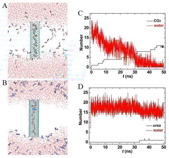
Figure 8.
The transport properties of (7,7) FCNT in the lipid bilayer. (A,B) Snapshots at t = 50 ns, the lipid membranes are not shown for clarity. (C,D) Number of water, CO2, and urea within FCNT as a function of simulation time.
3.6. PMF Profiles of Small Molecules across CNTs
Eventually, we computed the free energy of CO2 and urea across the two CNTs, depicted by PMF profiles in Figure 9. It was found that there was no energy barrier for CO2 at the entrance of both PCNT and FCNT. On the other hand, CO2 had lower free energy in the CNT (−20.4 kJ/mol for PCNT and −29.7 kJ/mol for FCNT) than in the lipid headgroups as well as in the water. As a comparison, the free energy of CO2 in the lipid bilayer was only −6.5 kJ/mol (Figure 9C), much higher than that in the CNTs, indicating that CO2 in the CNTs was energetically favorable. As to urea molecules, the PMF kept rising and reached the highest peak (approximate 50 kJ/mol) at the bilayer center, which is why urea molecules cannot permeate into the membrane. However, there was no energy barrier at the PCNT entrance, though urea molecules were accompanied by water molecules in the PCNT. However, the energy barrier at the FCNT entrance reached approximately 9.3 kJ/mol, due to the presence of the hydroxyl groups at the entrance of FCNT. Their electrostatic interactions with urea molecules prevented them from entering the FCNT.
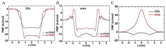
Figure 9.
Potential of mean force (PMF) profiles of CO2 and urea across the PCNT, FCNT, and lipid bilayer. (A) PMF profiles of CO2 across the PCNT and FCNT. (B) PMF profiles of urea across the PCNT and FCNT. (C) PMF profiles of CO2 and urea across the lipid bilayer. The reference point of zero potential energy was set at z = 3.5 nm, where the interactions between CO2/urea and CNTs can be ignored.
4. Conclusions
In summary, using MD simulations, we studied the translocation of PCNT from the aqueous environment to the lipid bilayer interior and compared the behavior of PCNT in the membrane with that of FCNT. We found that the PCNT can readily enter the membrane and preferred to stay therein without specific orientation if the length of PCNT was less than bilayer thickness. With the increasing length of PCNT, the rotation of PCNT in the bilayer center became more and more difficult. With the cooperation of the electrostatic interactions between the functional groups and lipid headgroups, FCNT was kept almost vertical in the membrane and was more suitable than PCNT to deliver drugs. Tentative simulations of the transport properties of CNT embedded in the bilayer center show that both small hydrophobic and hydrophilic molecules could enter the PCNT hollow channels, but urea molecules found it hard to penetrate the FCNT. The PMF profile demonstrated that there was a high energy barrier to prevent the entrance of urea at the two FCNT ends. Further studies should be focused on the specific transportation of small drug molecules through adjusting the radii of CNTs and functionalization.
Supplementary Materials
The following are available online at https://www.mdpi.com/2076-3417/9/20/4271/s1.
Author Contributions
Y.G. and D.M. performed the simulations and wrote the paper. J.W., W.X., and G.Z. set up the simulation systems. S.Z., L.C., and Z.W. analyzed the results and prepared all figures. J.C. revised the paper. All authors discussed the results and reviewed the manuscript.
Funding
This work was supported by the National Natural Science Foundation of China (Grant No. 11875236, 61575178, 11574272, U1832150), the Zhejiang Provincial Natural Science Foundation of China (Grant No. LY18A040001), the Students’ Scientific Research and Training Program of Zhejiang A&F University (Grant No. 2013200034) and Zhejiang Provincial Science and Technology Project (Grant No. LGN18C200017).
Conflicts of Interest
The authors declare no conflict of interest.
References
- Kostarelos, K.; Bianco, A.; Prato, M. Promises, facts and challenges for carbon nanotubes in imaging and therapeutics. Nat. Nanotechnol. 2009, 4, 627–633. [Google Scholar] [CrossRef]
- Ménard-Moyon, C.; Kostarelos, K.; Prato, M.; Bianco, A. Functionalized carbon nanotubes for probing and modulating molecular functions. Chem. Biol. 2010, 17, 107–115. [Google Scholar] [CrossRef]
- Cherukuri, P.; Bachilo, S.M.; Litovsky, S.H.; Weisman, R.B. Near-infrared fluorescence microscopy of single-walled carbon nanotubes in phagocytic cells. J. Am. Chem. Soc. 2004, 126, 15638–15639. [Google Scholar] [CrossRef]
- Kam, N.W.S.; Jessop, T.C.; Wender, P.A.; Dai, H. Nanotube molecular transporters: Internalization of carbon nanotube-protein conjugates into mammalian cells. J. Am. Chem. Soc. 2004, 126, 6850–6851. [Google Scholar] [CrossRef]
- Lu, Q.; Moore, J.M.; Huang, G.; Mount, A.S.; Rao, A.M.; Larcom, L.L.; Ke, P.C. RNA polymer translocation with single-walled carbon nanotubes. Nano Lett. 2004, 4, 2473–2477. [Google Scholar] [CrossRef]
- Pantarotto, D.; Briand, J.-P.; Prato, M.; Bianco, A. Translocation of bioactive peptides across cell membranes by carbon nanotubes. Chem. Commun. 2004, 10, 16–17. [Google Scholar] [CrossRef]
- Chen, X.; Kis, A.; Zettl, A.; Bertozzi, C.R. A cell nanoinjector based on carbon nanotubes. Proc. Natl Acad. Sci. USA 2007, 104, 8218–8222. [Google Scholar] [CrossRef]
- Villa, C.H.; Dao, T.; Ahearn, I.; Fehrenbacher, N.; Casey, E.; Rey, D.A.; Korontsvit, T.; Zakhaleva, V.; Batt, C.A.; Philips, M.R.; et al. Single-walled carbon nanotubes deliver peptide antigen into dendritic cells and enhance IgG responses to tumor-associated antigens. ACS Nano 2011, 5, 5300–5311. [Google Scholar] [CrossRef]
- Manna, S.K.; Sarkar, S.; Barr, J.; Wise, K.; Barrera, E.V.; Jejelowo, O.; Rice-Ficht, A.C.; Ramesh, G.T. Single-walled carbon nanotube induces oxidative stress and activates nuclear transcription factor-κB in human keratinocytes. Nano Lett. 2005, 5, 1676–1684. [Google Scholar] [CrossRef]
- Lam, C.-W.; James, J.T.; McCluskey, R.; Hunter, R.L. Pulmonary toxicity of single-wall carbon nanotubes in mice 7 and 90 days after intratracheal instillation. Toxicol. Sci. 2003, 77, 126–134. [Google Scholar] [CrossRef]
- Chen, X.; Tam, U.C.; Czlapinski, J.L.; Lee, G.S.; Rabuka, D.; Zettl, A.; Bertozzi, C.R. Interfacing carbon nanotubes with living cells. J. Am. Chem. Soc. 2006, 128, 6292–6293. [Google Scholar] [CrossRef] [PubMed]
- Jia, G.; Wang, H.; Yan, L.; Wang, X.; Pei, R.; Yan, T.; Zhao, Y.; Guo, X. Cytotoxicity of carbon nanomaterials: Single-wall nanotube, multi-wall nanotube, and fullerene. Environ. Sci. Technol. 2005, 39, 1378–1383. [Google Scholar] [CrossRef] [PubMed]
- Tyurina, Y.Y.; Kisin, E.R.; Murray, A.; Tyurin, V.A.; Kapralova, V.I.; Sparvero, L.J.; Amoscato, A.A.; Samhan-Arias, A.K.; Swedin, L.; Lahesmaa, R. Global phospholipidomics analysis reveals selective pulmonary peroxidation profiles upon inhalation of single-walled carbon nanotubes. ACS Nano 2011, 5, 7342–7353. [Google Scholar] [CrossRef] [PubMed]
- Wang, J.; Sun, P.; Bao, Y.; Liu, J.; An, L. Cytotoxicity of single-walled carbon nanotubes on PC12 cells. Toxicol. In Vitro 2011, 25, 242–250. [Google Scholar] [CrossRef] [PubMed]
- Reddy, A.R.N.; Reddy, Y.N.; Krishna, D.R.; Himabindu, V. Multi wall carbon nanotubes induce oxidative stress and cytotoxicity in human embryonic kidney (HEK293) cells. Toxicology 2010, 272, 11–16. [Google Scholar] [CrossRef] [PubMed]
- Porter, A.E.; Gass, M.; Muller, K.; Skepper, J.N.; Midgley, P.A.; Welland, M. Direct imaging of single-walled carbon nanotubes in cells. Nat. Nanotechnol. 2007, 2, 713–717. [Google Scholar] [CrossRef] [PubMed]
- Khodakovskaya, M.; Dervishi, E.; Mahmood, M.; Xu, Y.; Li, Z.; Watanabe, F.; Biris, A.S. Carbon nanotubes are able to penetrate plant seed coat and dramatically affect seed germination and plant growth. ACS Nano 2009, 3, 3221–3227. [Google Scholar] [CrossRef]
- Geng, J.; Kim, K.; Zhang, J.; Escalada, A.; Tunuguntla, R.; Comolli, L.R.; Allen, F.I.; Shnyrova, A.V.; Cho, K.R.; Munoz, D.; et al. Stochastic transport through carbon nanotubes in lipid bilayers and live cell membranes. Nature 2014, 514, 612–615. [Google Scholar] [CrossRef]
- Tunuguntla, R.H.; Henley, R.Y.; Yao, Y.C.; Pham, T.A.; Wanunu, M.; Noy, A. Enhanced water permeability and tunable ion selectivity in subnanometer carbon nanotube porins. Science 2017, 357, 792–796. [Google Scholar] [CrossRef]
- Zeng, S.; Chen, J.; Wang, X.; Zhou, G.; Chen, L.; Dai, C. Selective Transport through the ultrashort carbon nanotubes embedded in lipid bilayers. J. Phys. Chem. C 2018, 122, 27681–27688. [Google Scholar] [CrossRef]
- Chen, J.; Zhou, G.; Chen, L.; Wang, Y.; Wang, X.; Zeng, S. Interaction of graphene and its oxide with lipid membrane: A molecular dynamics simulation study. J. Phys. Chem. C 2016, 120, 6225–6231. [Google Scholar] [CrossRef]
- Wong-Ekkabut, J.; Baoukina, S.; Triampo, W.; Tang, I.M.; Tieleman, D.P.; Monticelli, L. Computer simulation study of fullerene translocation through lipid membranes. Nat. Nanotechnol. 2008, 3, 363–368. [Google Scholar] [CrossRef] [PubMed]
- Wallace, E.J.; Sansom, M.S.P. Blocking of carbon nanotube based nanoinjectors by lipids: A simulation study. Nano Lett. 2008, 8, 2751–2756. [Google Scholar] [CrossRef] [PubMed]
- Parthasarathi, R.; Tummala, N.R.; Striolo, A. Embedded single-walled carbon nanotubes locally perturb DOPC phospholipid bilayers. J. Phys. Chem. B 2012, 116, 12769–12782. [Google Scholar] [CrossRef] [PubMed]
- Qiao, R.; Roberts, A.P.; Mount, A.S.; Klaine, S.J.; Ke, P.C. Translocation of C60 and its derivatives across a lipid bilayer. Nano Lett. 2007, 7, 614–619. [Google Scholar] [CrossRef] [PubMed]
- Kraszewski, S.; Picaud, F.; Elhechmi, I.; Gharbi, T.; Ramseyer, C. How long a functionalized carbon nanotube can passively penetrate a lipid membrane. Carbon 2012, 50, 5301–5308. [Google Scholar] [CrossRef]
- Kraszewski, S.; Bianco, A.; Tarek, M.; Ramseyer, C. Insertion of short amino-functionalized single-walled carbon nanotubes into phospholipid bilayer occurs by passive diffusion. PLoS ONE 2012, 7, e40703. [Google Scholar] [CrossRef]
- Lacerda, L.; Ali-Boucetta, H.; Kraszewski, S.; Tarek, M.; Prato, M.; Ramseyer, C.; Kostarelos, K.; Bianco, A. How do functionalized carbon nanotubes land on, bind to and pierce through model and plasma membranes. Nanoscale 2013, 5, 10242–10250. [Google Scholar] [CrossRef]
- Berger, O.; Edholm, O.; Jahnig, F. Molecular dynamics simulations of a fluid bilayer of dipalmitoylphosphatidylcholine at full hydration, constant pressure, and constant temperature. Biophys. J. 1997, 72, 2002–2013. [Google Scholar] [CrossRef]
- Hummer, G.; Rasaiah, J.C.; Noworyta, J.P. Water conduction through the hydrophobic channel of a carbon nanotube. Nature 2001, 414, 188–190. [Google Scholar] [CrossRef]
- Schuttelkopf, A.W.; van Aalten, D.M. PRODRG: A tool for high-throughput crystallography of protein-ligand complexes. Acta Crystallogr. D Biol. Crystallogr. 2004, 60, 1355–1363. [Google Scholar] [CrossRef] [PubMed]
- Jorgensen, W.L.; Chandrasekhar, J.; Madura, J.D.; Impey, R.W.; Klein, M.L. Comparison of simple potential functions for simulating liquid water. J. Phys. Chem. 1983, 79, 926–936. [Google Scholar] [CrossRef]
- Oostenbrink, C.; Villa, A.; Mark, A.E.; Van Gunsteren, W.F. A biomolecular force field based on the free enthalpy of hydration and solvation: The GROMOS force-field parameter sets 53A5 and 53A. J. Comput. Chem. 2004, 25, 1656–1676. [Google Scholar] [CrossRef] [PubMed]
- Berendsen, H.J.; van der Spoel, D.; van Drunen, R. GROMACS: A message-passing parallel molecular dynamics implementation. Comput. Phys. Commun. 1995, 91, 43–56. [Google Scholar] [CrossRef]
- Hess, B.; Kutzner, C.; van der Spoel, D.; Lindahl, E. GROMACS 4: Algorithms for highly efficient, load-balanced, and scalable molecular simulation. J. Chem. Theory Comput. 2008, 4, 435–447. [Google Scholar] [CrossRef] [PubMed]
- Darden, T.; York, D.; Pedersen, L. Particle mesh Ewald: An Nlog(N) method for Ewald sums in large systems. J. Chem. Phys. 1993, 98, 10089–10092. [Google Scholar] [CrossRef]
- Essmann, U.; Perera, L.; Berkowitz, M.L.; Darden, T.; Lee, H.; Pedersen, L.G. A smooth particle mesh Ewald method. J. Chem. Phys. 1995, 103, 8577–8593. [Google Scholar] [CrossRef]
- Berendsen, H.J.C.; Postma, J.P.M.; van Gunsteren, W.F.; DiNola, A.; Haak, J.R. Molecular dynamics with coupling to an external bath. J. Chem. Phys. 1984, 81, 3684–3691. [Google Scholar] [CrossRef]
- Bussi, G.; Donadio, D.; Parrinello, M. Canonical sampling through velocity rescaling. J. Chem. Phys. 2007, 126, 014101. [Google Scholar] [CrossRef]
- Hess, B.; Bekker, H.; Berendsen, H.J.; Fraaije, J.G. LINCS: A linear constraint solver for molecular simulations. J. Comput. Chem. 1997, 18, 1463–1472. [Google Scholar] [CrossRef]
- Miyamoto, S.; Kollman, P.A. SETTLE: An analytical version of the SHAKE and RATTLE algorithm for rigid water models. J. Comput. Chem. 1992, 13, 952–962. [Google Scholar] [CrossRef]
- Lemkul, J.A.; Bevan, D.R. Assessing the stability of Alzheimer’s amyloid protofibrils using molecular dynamics. J. Phys. Chem. B 2004, 114, 1652–1660. [Google Scholar] [CrossRef] [PubMed]
- Park, S.; Schulten, K. Calculating potentials of mean force from steered molecular dynamics simulations. J. Chem. Phys. 2004, 120, 5946–5961. [Google Scholar] [CrossRef] [PubMed]
- Hub, J.S.; De Groot, B.L.; Van Der Spoel, D. G_whams: A free weighted histogram analysis implementation including robust error and autocorrelation estimates. J. Chem. Theory Comput. 2010, 6, 3713–3720. [Google Scholar] [CrossRef]
© 2019 by the authors. Licensee MDPI, Basel, Switzerland. This article is an open access article distributed under the terms and conditions of the Creative Commons Attribution (CC BY) license (http://creativecommons.org/licenses/by/4.0/).