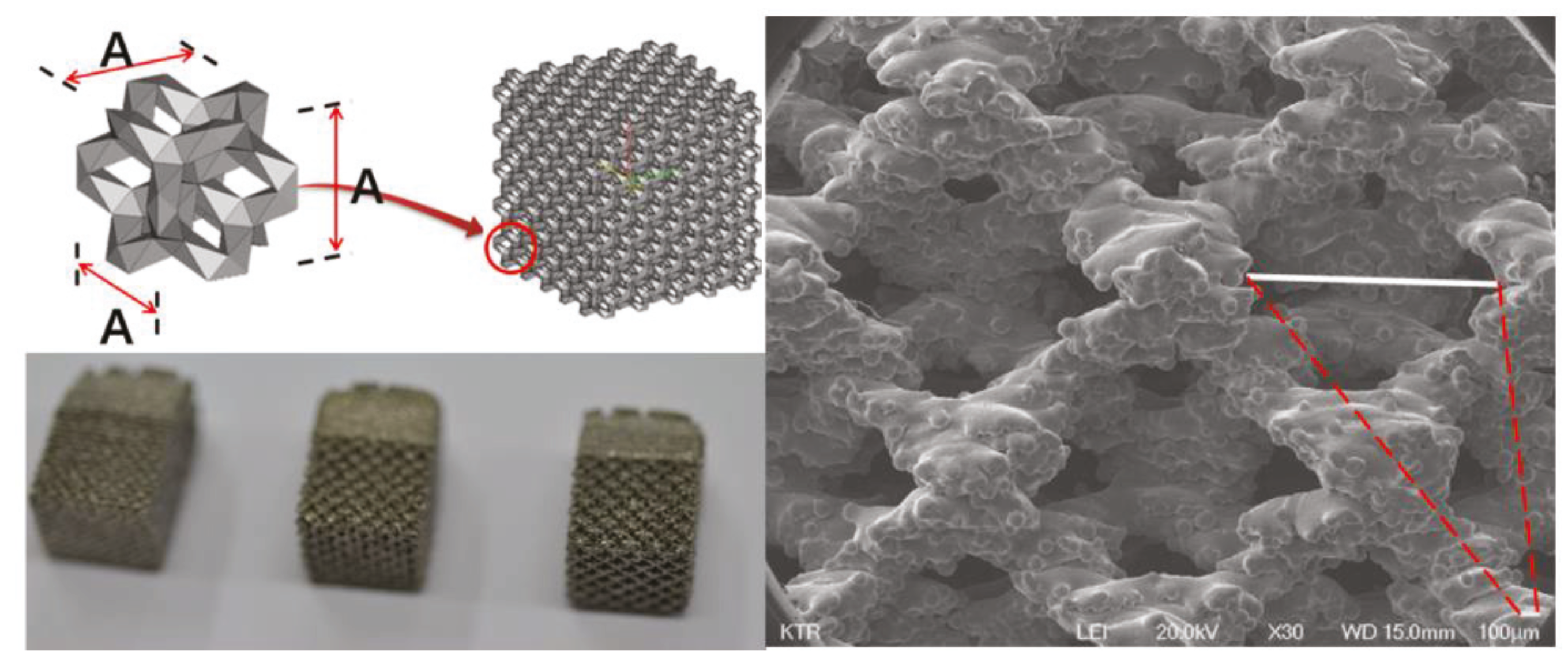
2.1. Verification of Porosity Size, Structural Design, and Structural Coherence
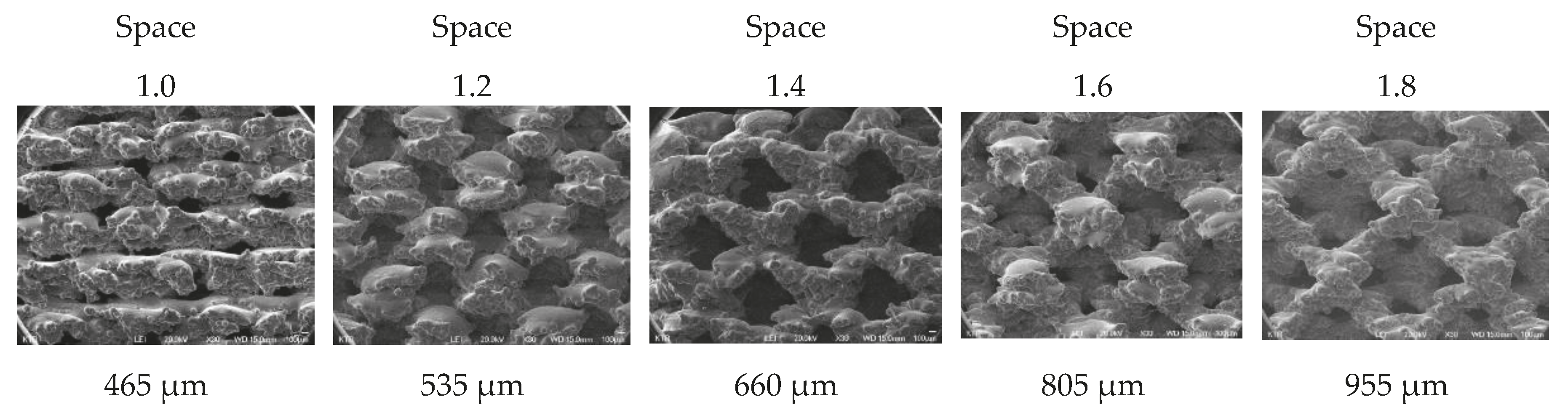
It is known that the pore size of human cancellous bone ranges from 500 to 600 nm [
6]. Thus, to find similar pore sizes, a total of five samples were fabricated by varying the pore size (1.0 mm to 1.8 mm, 0.2 mm spacing) using preprocessed commercial software MAGICS RP (Materialize NV, Leuven, Belgium). Scanning electron microscope (SEM) images for all of the faces of the five specimens were photographed at ×30 ratio. The results were measured, and the average value was calculated after measuring the pores of each face one at a time (
Figure 1).
Next, an animal experiment was conducted to confirm the degree of bone fusion of each type of porous structure. The purpose of this experiment was to test the strength of separation from the bone after six weeks, when implanting the specimens into the bones of rabbits. We take the high strength result of push down testing to mean that the structure is well-coupled with the bone and through this, it is possible to select the structure that can enhance the higher integration rate, which is the main purpose of spinal cages. We developed a spinal cage made of the above structure that also gives a higher integration rate along with enhanced merging of bone. Rabbit femur was chosen because it was not suitable to transplant the specimen to the spine of a small animal, and the femur was suitable for cutting and preparing the specimen for a second push down test. Additionally, the femur is made up of cortical bone on the inside and cancellous bone on the outside, providing an environment similar to the vertebrate.
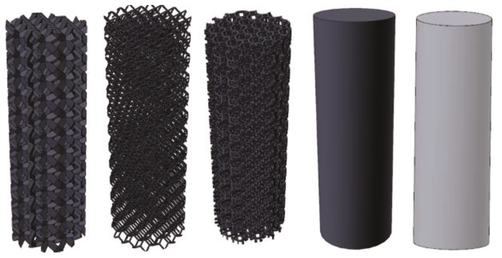
The five samples of different porous structure and solid structure were designed with a diameter of 2 mm and a length of 6 mm according to the international standard test method (ISO10993-6: 2007). The samples were printed using electron beam melting (EBM) within an ARCAM A1 (ARCAM AB, Mölnlycke, Sweden). (
Figure 2) During the EBM process, the electron beam melts metal powder layer-by-layer to build the implant. The vacuum environment in the EBM machine maintains the chemical composition of the material and provides an excellent environment for building parts in reactive materials such as titanium alloys. The high power of the electron beam ensures a high rate of deposition and an even temperature distribution within the part. The results trigger full melting of the metal powder and high strength properties of the material. The EBM machine titanium Ti6Al4V ELI (Grade 23) is a gas-atomized powder with a particle size between 45 and 100 microns. This limit on the minimum particle size ensures safe handling of the powder. Ti6Al4V-ELI has numerous applications in the medical industry. The biocompatibility of Ti6Al4V-ELI is excellent, especially when direct contact with tissue or bone is required. A powder remover system machine (PRS Machine, ARCAM AB, Mölnlycke, Sweden) was used to remove any remaining titanium powder on the completed samples. All products are made of titanium alloy (Ti6Al4V-ELI per ASTM-F136). Specimens 1 to 4 were fabricated using 3D printing with titanium powder, and Specimen 5 was fabricated using bar material.
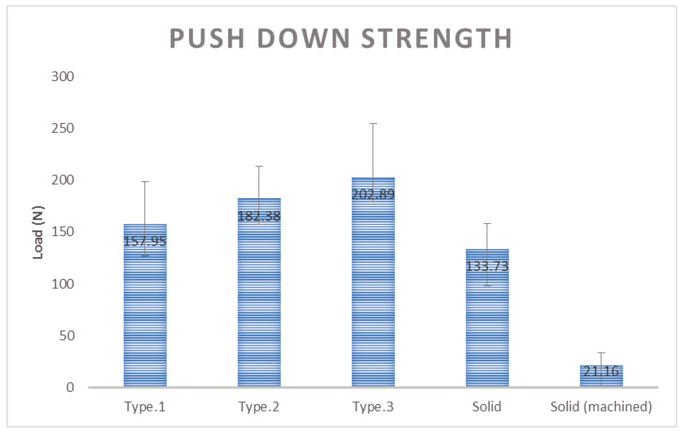
Each type of structure was inserted into the femur of the New Zealand White Rabbit and the rabbit’s femur was collected at 6 weeks after the insertion. The purpose of push down testing is to implant a specific sample into the bone of an animal and to determine the degree of bone fusion after a certain period of time. Usually after six weeks, there is improved strength, and the push down testing is to check the degree of deviation by sliding the specimen into an axial direction by cutting the specimen so that it can be mounted on the mechanical testing machine. The better strength can preserve the bone fusion with stability.
The push down test was performed using MTS 858 Bionix (MTS System Corp, Eden Prairie, MN, USA) to measure the mechanical strength at which the specimen is released from the bone. The experimental group with the specimens applied three kinds of additive manufactured porous structure (G Structure, Dode Thin Structure and Octa Dense Structure) and those with additive manufactured solid structure specimens without porous structure were compared and evaluated with the control group, consisting of specimens that were fabricated with titanium alloy rods using the general machining method.
2.2. Design and Prototyping of Porous Compound Cage
Porous composite fusion cages have several design requirements. The instrument should induce bone fusion after surgery and should be able to reduce subsidence compared to conventional titanium alloy commercial products, and the fused complex should not be separated. Also, special equipment dedicated to surgery is required, and the connection must be possible between two instruments and separation also must be possible after surgery.
Ti6Al4V-ELI (per ASTM F136) material, which has been widely used and already verified [
11,
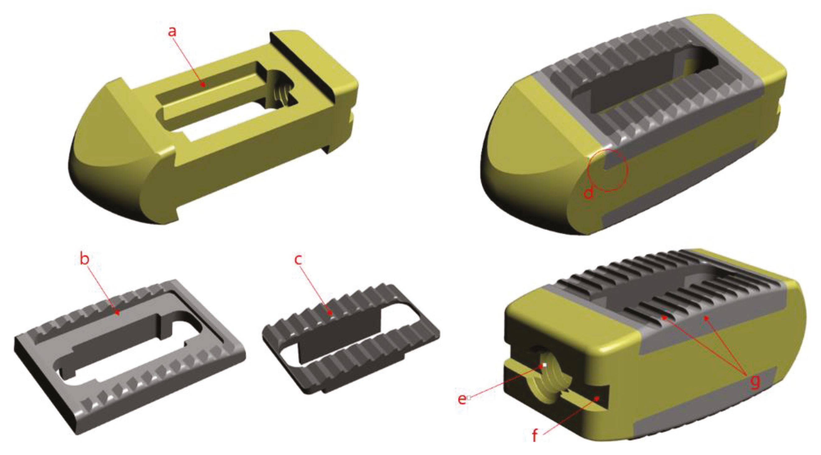
12] as a medical device material for orthopedics and neurosurgery to improve bone union rate, was selected, and the porous structure and size confirmed through animal experiments were applied. The porous structure of the spinal fusion cage is advantageous for increasing the bone union rate, but due to the unique rough surface, there is a risk of damage to the nerves and blood vessels during the insertion of the cage in surgery. Therefore, the side part has a solid structure that was treated with polishing, and only the center of the vertebral end plate is designed as a porous structure.
To reduce subsidence, medical PEEK (polyetheretherketone per ASTM F2026), which is a typical biomaterial, was selected. PEEK is known to have similar elastic moduli to human cancellous bone.
Since two different materials are were being combined, they were not to be separated after surgery. Also, because it is difficult to use adhesives to combine the two components, because the medical device is inserted in the living body, a precision machining method was used to combine the two materials. Thus, it completely restrained the three directions and minimized the possibility of separation into a dove-tail structure. The PEEK was constructed with a pocket inside and a slanted side, so that it could not come out again when the metal part was forcibly pushed in from above.
In order to use the cage, a device called a cage holder was necessary. It has a structure in which the cage and the holder are connected and can be separated after the operation. Also, since excessive compression and rotational force are delivered during the operation, a sufficient fixing force of the portion connected to the cage was required. Therefore, a hole was drilled in the back of the cage and a 3 mm tap (M3 × Pitch 0.5 mm) was machined, and a rectangular pocket was used to prevent rotation. All designs and simulation verification were done using Solid works 2013 Premium (Dassault System, Vélizy-villacoublay, France), a commercial 3D CAD software. (
Figure 3).
The final prototype of the cover part was printed using EBM (Electron Beam Melting) within an ARCAM A1 (ARCAM AB, Mölnlycke, Sweden). The ARCAM EBM A1 machines use EBM. During the EBM process, the electron beam melts metal powder layer-by-layer to build the implant. The vacuum environment in the EBM machine maintains the chemical composition of the material and provides an excellent environment for building parts in reactive materials such as titanium alloys. The high power of the electron beam ensures a high rate of deposit and an even temperature distribution within the part. The results trigger the full melting of the metal powder and high strength properties of the material. The EBM machine titanium Ti6Al4V ELI (Grade 23) is a gas-atomized powder with a particle size between 45 and 100 microns. This limit on the minimum particle size ensures safe handling of the powder. Ti6Al4V-ELI has numerous applications in the medical industry. The biocompatibility of Ti6Al4V-ELI is excellent, especially when direct contact with tissue or bone is required. A powder remover system machine (ARCAM AB, Mölnlycke, Sweden) was used to remove any remaining titanium powder on the completed metal cover. However, due to the nature of additive manufacturing, it was not suitable for precision machining and thus the parts to be assembled with the PEEK parts were further precisely machined using 5-axial Milling (DMU50, DMG Mori., Bielefeld, Germany). In the case of the PEEK part, a 20 mm bar material was fabricated using a CNC (Computer Numerical Control) machine (SR20J, Star Corp., Shizuoka, Japan), and the final prototype was completed using the interference fit method.
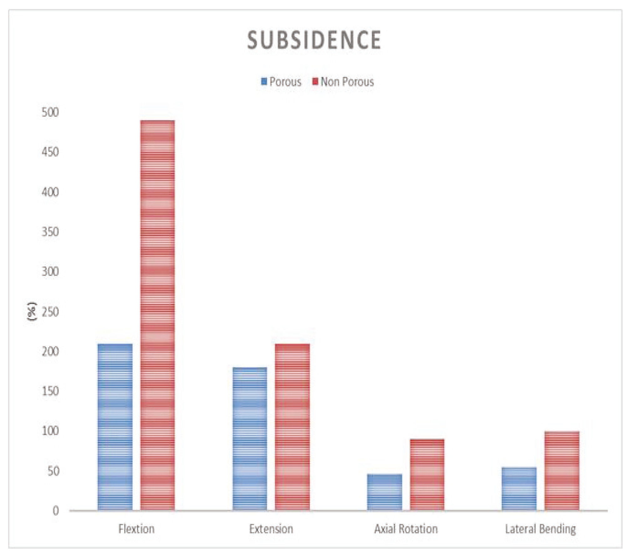
2.3. Comparison of Subsidence Likelihood Through Analysis of Lumbar Finite Element Model
Three-dimensional anatomical and geometric shape information of an adult male normal lumbar CT data was derived using commercial software (Mimics 17.0, Materialise, Leuven, Belgium) and the data were analyzed using commercially available software (Rhinoceros 3.0, Robert McNeel and Associate Corp., Seattle, WA, USA) by extracting the vectorized shapes of the outer and inner boundaries for each. Solid image construction and meshing were performed using commercial software (Patran 2006, MSC Software Corp, Newport Beach, CA, USA) for the extracted images, and the vertebral bodies were defined with isotropy material characteristics. The annulus of fibrocartilaginous intervertebral disk was modeled with orthotropic material and the nucleus of fibrocartilaginous intervertebral disc was modeled with incompressible fluid to complete final model of the lumbar finite element. The lumbar spine model used in this study was one that was already proven in previous studies [
13].
The finite element surgical model was implemented using the porous composite cage developed in this study. The height of the composite fusion cage was set to be 10 mm in width, 11 mm in length and 25 mm in length. The properties of the titanium cover (elastic modulus 114 GPa, Poisson’s ratio 0.3 GPa) were set at PEEK (elastic modulus 3.5 GPa and Poisson’s ratio 0.3 GPa). To analyze the subsidence likelihood with or without porosity, two models, one with and one without porous structure, were implemented.
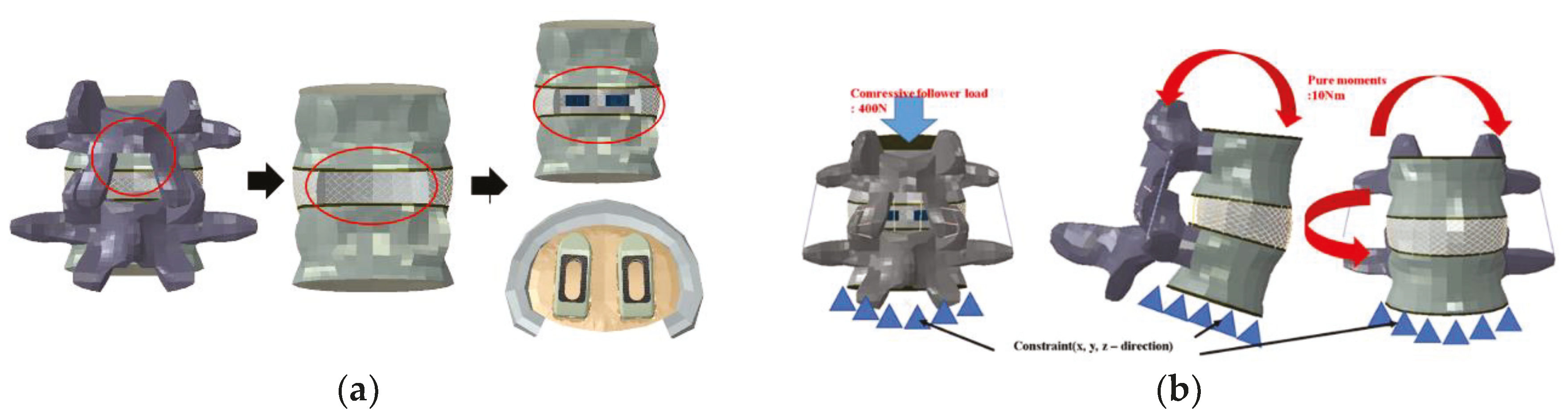
In implementing the finite element model, it was assumed the complete coupling between the parts of the device and the thread of the end plate was simplified. For each instrument, a portion of the disc was removed after partial laminectomy and partial resection of the vertebral body by the PLIF procedure in the L4–L5 segment, and two spinal fusion cages were inserted in parallel.
In implementing the finite element model, it was assumed the complete coupling between the parts of the device and the thread of the end plate was simplified. For each instrument, a portion of the disc was removed after partial laminectomy and partial resection of the vertebral body by the PLIF procedure in the L4–L5 segment, and two spinal fusion cages were inserted in parallel (
Figure 4a).
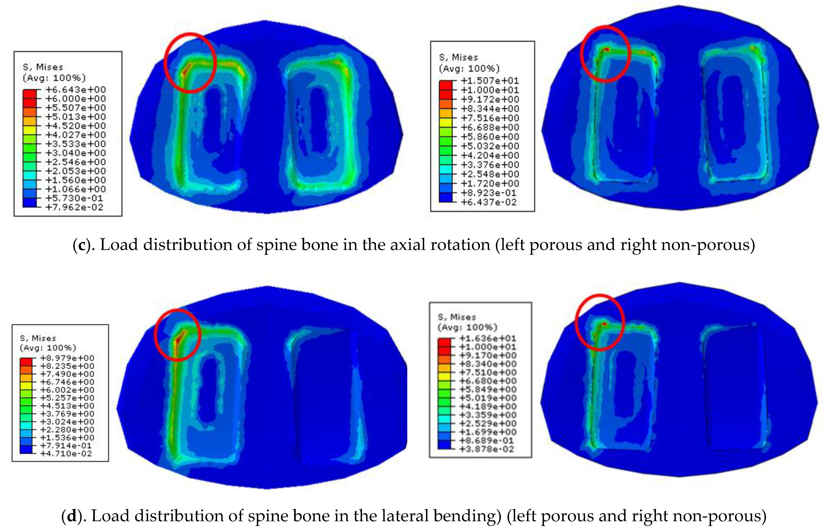
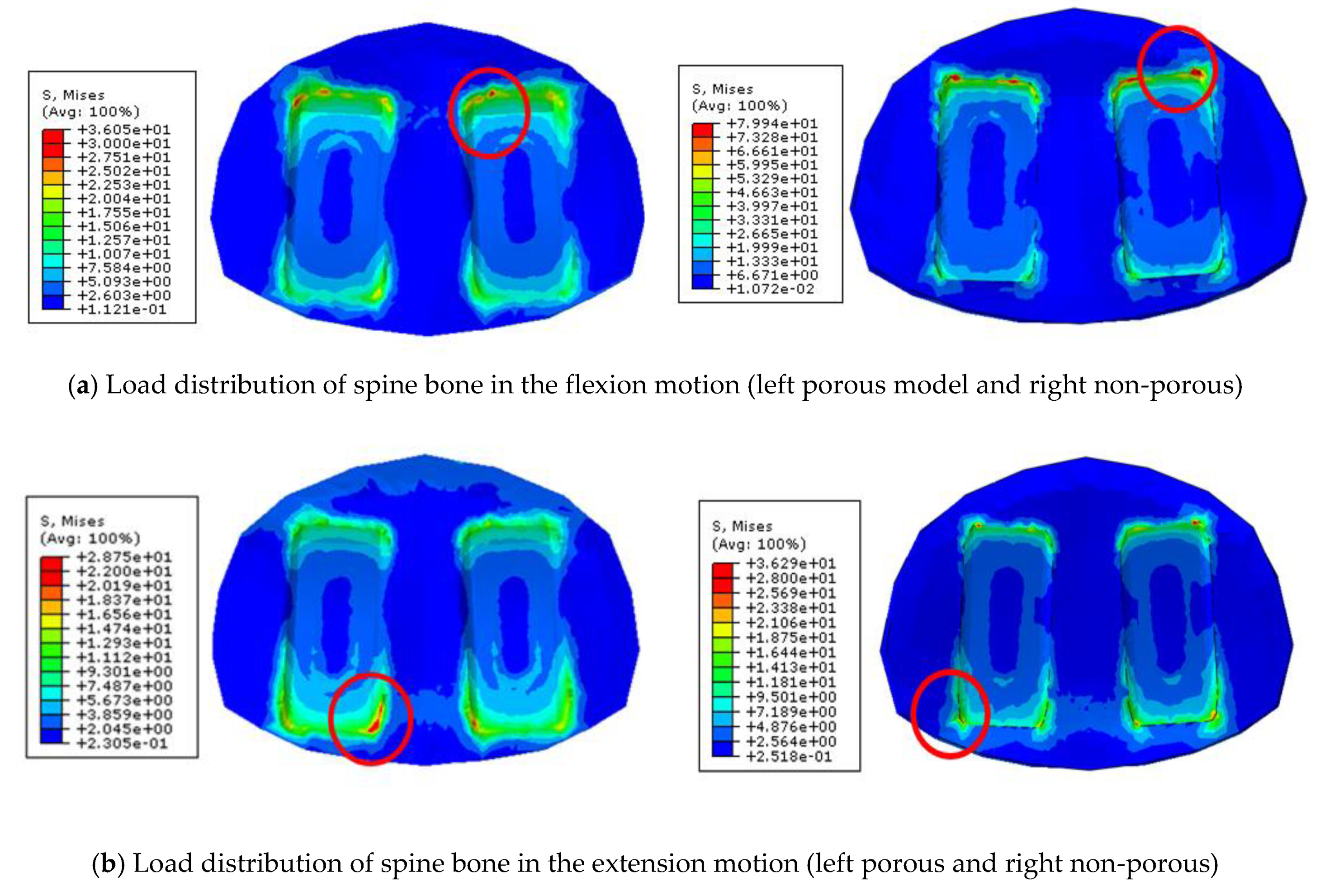
To implement the physiological loading conditions, the tide-contact conditions were applied to contact surfaces between bone and all surgical instruments in order to achieve a perfect bone fusion, as shown in
Figure 4. A 400 N compressive follower pre-load and a 10 Nm pure moment were applied to the L4 superior endplate, and the L5 inferior endplate was constrained to prevent displacement in all directions. After applying a force of flexion/extension (10 Nm), axial rotation (10 Nm), and lateral bending (5 Nm), respectively, the results were evaluated (
Figure 4b). The maximum stress of the cancellous bone of the cage and vertebral body interface were compared and analyzed after each motion, and the analysis was performed using ABAQUS/Standard V 6.10 (Simulia Corp, Providence, RI, USA), a commercial finite element analysis software.
2.4. Verification of Manufactured Prototype
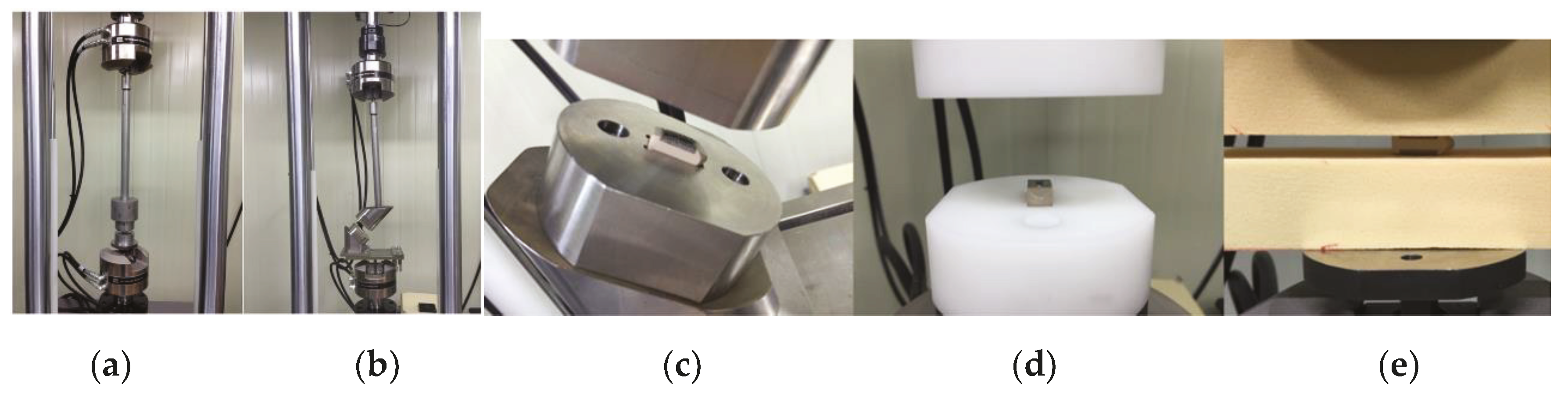
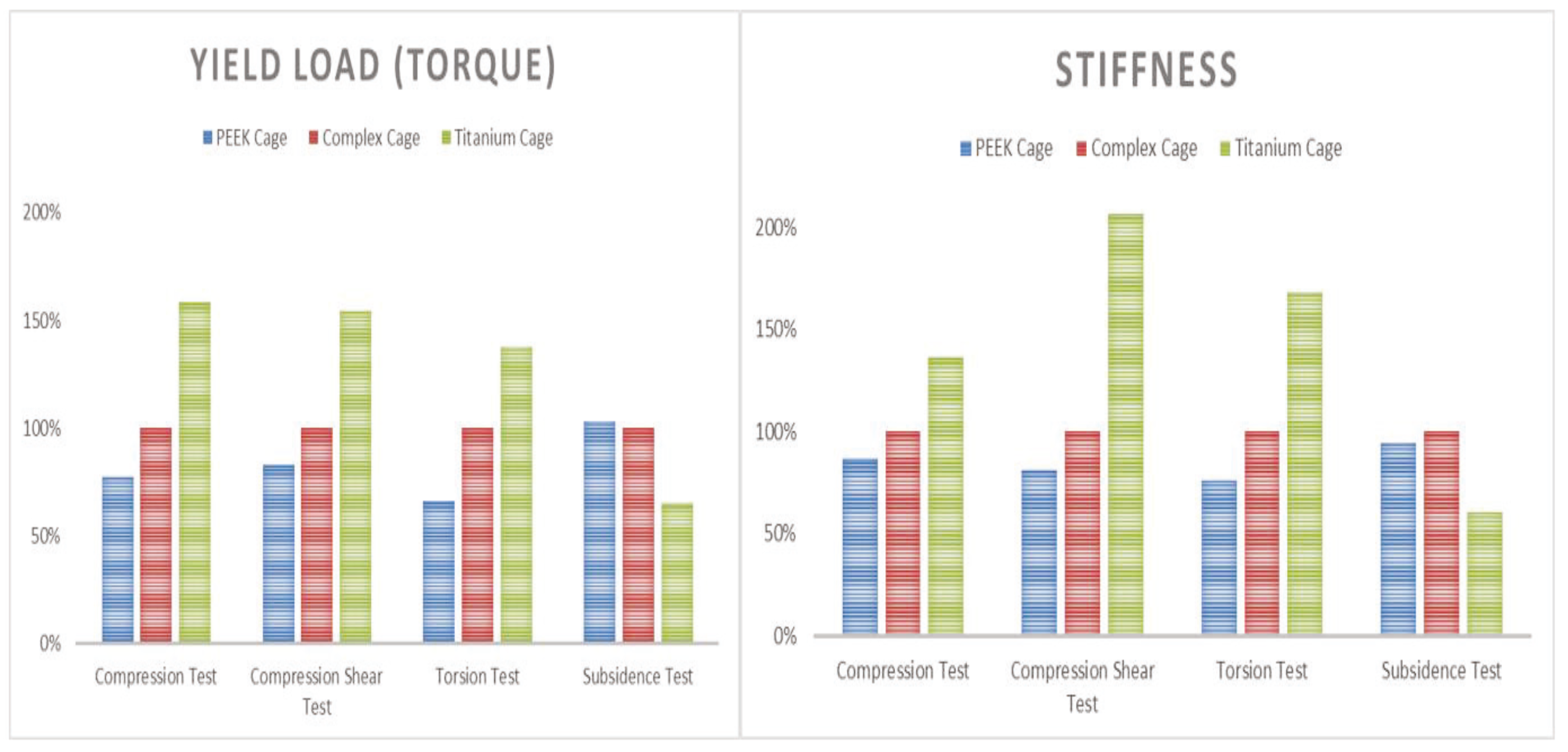
Static compression shear static torsion test, and static torsion test were performed in order to identify the possible movements in the human spine, and a dynamic compression test was performed to confirm the problems caused by the cyclic loading, referencing ASTM-F2077, an international standard of the spinal fusion cage. In order to identify the likelihood of subsidence of the fabricated prototype, a subsidence test was performed with reference to international standard ASTM F2267, and an MTS 858 Bionix (MTS System Corp, Eden Prairie, MN, USA) was used for the mechanical load. To compare the performance with the fusion cage, commercial PEEK materials were compared with the fusion cage (LP Cage, Medyssey, Chungcheongbuk-do, Korea) and titanium alloy material fusion cage (LT Cage, Medyssey, Chungcheongbuk-do, Korea). For accurate comparison, the lengths and widths of all three products were kept consistent, and both of the selected fusion cages were approved by the Korean Food and Drug Administration and the US FDA 510K. Their results were normalized with the composite fusion cage and compared.
The jig was designed to transfer the force to the fusion cage according to the standards of ASTM F2077 and F2267. The jig was designed and manufactured for compression, torsion, subsidence and shear according to the direction of each force. For each test, stainless steel was used for the static test, poly acetal was used for the dynamic test, and PU (Polyurethane) foam material was used for the subsidence test (
Figure 5).
Static compression, compression shear, and subsidence tests were performed six times and averaged by applying loads (load, N) and displacement at a rate of 25 mm/min to obtain the data. Torsional strength (torque, Nm) and angle (angle, degree) were obtained by applying static torsion at a rate of 60 degrees/min, and the measurement was conducted six times to obtain data, and data were averaged. In the dynamic compression test, the R-ratio was set at 10% and 5,000,000 cycles were tested at a frequency of 5 Hz. The applied load was determined by the static compression load value, and the applied load was decreased step by step. Fracture and deformation were confirmed [
14,
15].

