Abstract
Incidents of lumbar degenerative diseases, such as spinal stenosis and degenerative spondylolisthesis, are increasing due to the aging population, and as a result, posterior lumbar interbody fusion (PLIF) is widely used. However, the interbody fusion cage used in the fusion surgery has been reported to cause subsidence in the fusion cage of the titanium material and bone nonunion in the case of the polyetheretherketone (PEEK) material cage. Therefore, we aim to reduce the possibility of subsidence of the spinal fusion cage through its elastic modulus difference with the cortical bone of the vertebral body. For the vertebral end plate, which is related to the fusion rate, we also aim to design a new composite vertebral cage, which integrates a cover of porous structure using the additive manufacturing method of titanium alloy to fabricate a prototype, and to biomechanically verify the prototype. The method was as follows. In order to find a similar pore size of human cancellous bone, the pore size was adjusted and the results were measured with SEM. The pore size of each surface was measured individually and the mean value was calculated. Next, an animal experiment was conducted to confirm the degree of fusion of each structural type, and prototypes of various structures were fabricated. The degree of fusion was confirmed by a push down test. A prototype of the fusion cage composed of titanium and PEEK material was fabricated, and the possibility of subsidence by existence of porous structure was confirmed by using the lumbar spine finite element model. Then, the prototype was compared with the composite fusion cage developed by ASTM F2077 and ASTM F2267 methods, and with the commercial PEEK and titanium cages. As a result, the correlation between bone fusion and the porous structure, as well as size of the spine fusion cage composing the composite for porous structure and elasticity, was confirmed. Type 3 structures showed the best performance in bone fusion and the pore size of 1.2 mm was most suitable. In addition, the likelihood of subsidence of a cage with a porous structure was considered to be lower than that of a cage with a solid structure. When the new composite cage combined with two composites was compared with commercial products to verify, the performance was better than that of the existing PEEK material. The subsidence result was superior to the titanium product and showed similar results to PEEK products. In conclusion, the performance value was superior to the existing PEEK material, and the subsidence result was superior to the titanium product and was similar to the PEEK product, and thus, performance-wise, it is concluded that the PEEK product can be completely replaced with the new product.
1. Introduction
The incidence of lumbar degenerative diseases such as spinal stenosis and degenerative spondylolisthesis is increasing due to the aging population, and when there is no response to conservative treatments, then posterior lumbar interbody fusion (PLIF) is widely used [1]. The PLIF with cage insertion can achieve a firm interbody fusion and achieve stable coronal and sagittal alignment during the fusion. It is also considered a good method because it has an indirect nerve decompression effect by increasing the disc space that is commonly accompanied by degenerative lumbar diseases, thereby widening the nerve root [2,3].
Commonly used materials for spinal fusion cages are titanium alloy and PEEK. The titanium alloy material has a high modulus of elasticity and is reported to be highly susceptible to subsidence of the spinal fusion cage, due to the difference in elastic modulus of the cortical bone, and has the characteristic of providing excellent bone fusion [4] In contrast, the recently introduced PEEK spine fusion cage has a similar elastic modulus to the cortical bone of the vertebrae, and is favorable for load and stress dispersion. Therefore, it is known to show lower frequency in subsidence than the titanium alloy cage. However, the fusion rate is low and the probability of non-fusion is higher than that of the titanium alloy spinal fusion cage [5]
The main purpose of the spinal cage during spinal fusion is to fuse two vertebra bodies and to keep the height between them. However, the elastic modules of the spinal cage and the vertebra body cause subsidence, which means that the spinal cage enter the vertebra body and reduce the height between vertebra bodies. As a result, we might witness another disease such as pedicle stenosis and so on.
In order to solve the problem of the metal material, a measure was attempted to reduce the elastic modulus by manufacturing it in a porous structure. Yook et al. produced a titanium porous body via freeze forming (molding) method that has an elastic modulus of 4GPa and a compressive strength of 150 MPa with a porosity of 60% or more [6]. However, there was a problem with subsidence difference and the radiopacity of the metal itself, along with the MRI (Magnetic Resonance Imaging) artifact.
In order to solve the problem of the low synostosis rate that cannot directly combine with Peek-based bone, Yao et al. used ion plasma solvents to coat titanium less than 100 nm, and reported a 30% increase in the integration of bone cells, as compared to general titanium material and uncoated PEEK material [7,8]. Han conducted cellular and animal testing by coating titanium 1 μm thick with E-beam deposition [9]. As a result, cell integration, multiplication, differentiation, etc., were improved in comparison to general PEEK, and bone integration in the femur of rabbit was also reported to be improved by more than 50% [10]. However, there are still problems and limitations with this coating procedure.
Therefore, in this study, the body of the spinal fusion cage is made of PEEK material, which reduces the likelihood of subsidence of the spinal fusion cage, due to the difference of the elastic modulus with the spinal body cortical bone. For the vertebral end plate, which is related to the fusion rate, we aim to design a new composite vertebral cage by combining a cover of porous structure, using the additive manufacturing of titanium alloy material, to fabricate a prototype and then to biomechanically verify it.
2. Materials and Methods
2.1. Verification of Porosity Size, Structural Design, and Structural Coherence
It is known that the pore size of human cancellous bone ranges from 500 to 600 nm [6]. Thus, to find similar pore sizes, a total of five samples were fabricated by varying the pore size (1.0 mm to 1.8 mm, 0.2 mm spacing) using preprocessed commercial software MAGICS RP (Materialize NV, Leuven, Belgium). Scanning electron microscope (SEM) images for all of the faces of the five specimens were photographed at ×30 ratio. The results were measured, and the average value was calculated after measuring the pores of each face one at a time (Figure 1).
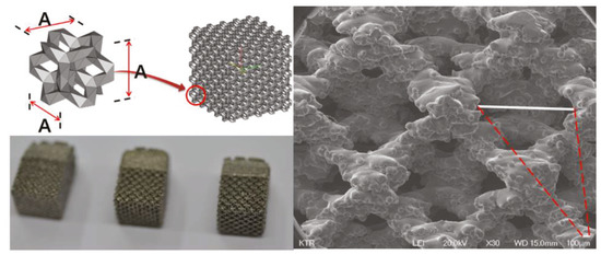
Figure 1.
The 3D printing porosity size samples for SEM.
Next, an animal experiment was conducted to confirm the degree of bone fusion of each type of porous structure. The purpose of this experiment was to test the strength of separation from the bone after six weeks, when implanting the specimens into the bones of rabbits. We take the high strength result of push down testing to mean that the structure is well-coupled with the bone and through this, it is possible to select the structure that can enhance the higher integration rate, which is the main purpose of spinal cages. We developed a spinal cage made of the above structure that also gives a higher integration rate along with enhanced merging of bone. Rabbit femur was chosen because it was not suitable to transplant the specimen to the spine of a small animal, and the femur was suitable for cutting and preparing the specimen for a second push down test. Additionally, the femur is made up of cortical bone on the inside and cancellous bone on the outside, providing an environment similar to the vertebrate.
The five samples of different porous structure and solid structure were designed with a diameter of 2 mm and a length of 6 mm according to the international standard test method (ISO10993-6: 2007). The samples were printed using electron beam melting (EBM) within an ARCAM A1 (ARCAM AB, Mölnlycke, Sweden). (Figure 2) During the EBM process, the electron beam melts metal powder layer-by-layer to build the implant. The vacuum environment in the EBM machine maintains the chemical composition of the material and provides an excellent environment for building parts in reactive materials such as titanium alloys. The high power of the electron beam ensures a high rate of deposition and an even temperature distribution within the part. The results trigger full melting of the metal powder and high strength properties of the material. The EBM machine titanium Ti6Al4V ELI (Grade 23) is a gas-atomized powder with a particle size between 45 and 100 microns. This limit on the minimum particle size ensures safe handling of the powder. Ti6Al4V-ELI has numerous applications in the medical industry. The biocompatibility of Ti6Al4V-ELI is excellent, especially when direct contact with tissue or bone is required. A powder remover system machine (PRS Machine, ARCAM AB, Mölnlycke, Sweden) was used to remove any remaining titanium powder on the completed samples. All products are made of titanium alloy (Ti6Al4V-ELI per ASTM-F136). Specimens 1 to 4 were fabricated using 3D printing with titanium powder, and Specimen 5 was fabricated using bar material.
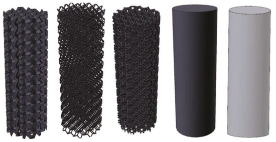
Figure 2.
The 3D printing design of animal experiment implant specimen: From the left—Additive Manufacturing Type 1, Additive Manufacturing Type 2, Additive Manufacturing type 3, Additive Manufacturing Solid and Machined Solid.
Each type of structure was inserted into the femur of the New Zealand White Rabbit and the rabbit’s femur was collected at 6 weeks after the insertion. The purpose of push down testing is to implant a specific sample into the bone of an animal and to determine the degree of bone fusion after a certain period of time. Usually after six weeks, there is improved strength, and the push down testing is to check the degree of deviation by sliding the specimen into an axial direction by cutting the specimen so that it can be mounted on the mechanical testing machine. The better strength can preserve the bone fusion with stability.
The push down test was performed using MTS 858 Bionix (MTS System Corp, Eden Prairie, MN, USA) to measure the mechanical strength at which the specimen is released from the bone. The experimental group with the specimens applied three kinds of additive manufactured porous structure (G Structure, Dode Thin Structure and Octa Dense Structure) and those with additive manufactured solid structure specimens without porous structure were compared and evaluated with the control group, consisting of specimens that were fabricated with titanium alloy rods using the general machining method.
2.2. Design and Prototyping of Porous Compound Cage
Porous composite fusion cages have several design requirements. The instrument should induce bone fusion after surgery and should be able to reduce subsidence compared to conventional titanium alloy commercial products, and the fused complex should not be separated. Also, special equipment dedicated to surgery is required, and the connection must be possible between two instruments and separation also must be possible after surgery.
Ti6Al4V-ELI (per ASTM F136) material, which has been widely used and already verified [11,12] as a medical device material for orthopedics and neurosurgery to improve bone union rate, was selected, and the porous structure and size confirmed through animal experiments were applied. The porous structure of the spinal fusion cage is advantageous for increasing the bone union rate, but due to the unique rough surface, there is a risk of damage to the nerves and blood vessels during the insertion of the cage in surgery. Therefore, the side part has a solid structure that was treated with polishing, and only the center of the vertebral end plate is designed as a porous structure.
To reduce subsidence, medical PEEK (polyetheretherketone per ASTM F2026), which is a typical biomaterial, was selected. PEEK is known to have similar elastic moduli to human cancellous bone.
Since two different materials are were being combined, they were not to be separated after surgery. Also, because it is difficult to use adhesives to combine the two components, because the medical device is inserted in the living body, a precision machining method was used to combine the two materials. Thus, it completely restrained the three directions and minimized the possibility of separation into a dove-tail structure. The PEEK was constructed with a pocket inside and a slanted side, so that it could not come out again when the metal part was forcibly pushed in from above.
In order to use the cage, a device called a cage holder was necessary. It has a structure in which the cage and the holder are connected and can be separated after the operation. Also, since excessive compression and rotational force are delivered during the operation, a sufficient fixing force of the portion connected to the cage was required. Therefore, a hole was drilled in the back of the cage and a 3 mm tap (M3 × Pitch 0.5 mm) was machined, and a rectangular pocket was used to prevent rotation. All designs and simulation verification were done using Solid works 2013 Premium (Dassault System, Vélizy-villacoublay, France), a commercial 3D CAD software. (Figure 3).
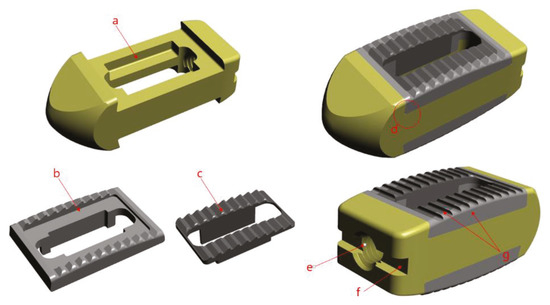
Figure 3.
Design image (a) pocket shape, (b) solid structure, (c) porous structure, (d) dove-tail joint, (e) M3mm tap, (f) rectangular Pocket, (g) polishing machining.
The final prototype of the cover part was printed using EBM (Electron Beam Melting) within an ARCAM A1 (ARCAM AB, Mölnlycke, Sweden). The ARCAM EBM A1 machines use EBM. During the EBM process, the electron beam melts metal powder layer-by-layer to build the implant. The vacuum environment in the EBM machine maintains the chemical composition of the material and provides an excellent environment for building parts in reactive materials such as titanium alloys. The high power of the electron beam ensures a high rate of deposit and an even temperature distribution within the part. The results trigger the full melting of the metal powder and high strength properties of the material. The EBM machine titanium Ti6Al4V ELI (Grade 23) is a gas-atomized powder with a particle size between 45 and 100 microns. This limit on the minimum particle size ensures safe handling of the powder. Ti6Al4V-ELI has numerous applications in the medical industry. The biocompatibility of Ti6Al4V-ELI is excellent, especially when direct contact with tissue or bone is required. A powder remover system machine (ARCAM AB, Mölnlycke, Sweden) was used to remove any remaining titanium powder on the completed metal cover. However, due to the nature of additive manufacturing, it was not suitable for precision machining and thus the parts to be assembled with the PEEK parts were further precisely machined using 5-axial Milling (DMU50, DMG Mori., Bielefeld, Germany). In the case of the PEEK part, a 20 mm bar material was fabricated using a CNC (Computer Numerical Control) machine (SR20J, Star Corp., Shizuoka, Japan), and the final prototype was completed using the interference fit method.
2.3. Comparison of Subsidence Likelihood Through Analysis of Lumbar Finite Element Model
Three-dimensional anatomical and geometric shape information of an adult male normal lumbar CT data was derived using commercial software (Mimics 17.0, Materialise, Leuven, Belgium) and the data were analyzed using commercially available software (Rhinoceros 3.0, Robert McNeel and Associate Corp., Seattle, WA, USA) by extracting the vectorized shapes of the outer and inner boundaries for each. Solid image construction and meshing were performed using commercial software (Patran 2006, MSC Software Corp, Newport Beach, CA, USA) for the extracted images, and the vertebral bodies were defined with isotropy material characteristics. The annulus of fibrocartilaginous intervertebral disk was modeled with orthotropic material and the nucleus of fibrocartilaginous intervertebral disc was modeled with incompressible fluid to complete final model of the lumbar finite element. The lumbar spine model used in this study was one that was already proven in previous studies [13].
The finite element surgical model was implemented using the porous composite cage developed in this study. The height of the composite fusion cage was set to be 10 mm in width, 11 mm in length and 25 mm in length. The properties of the titanium cover (elastic modulus 114 GPa, Poisson’s ratio 0.3 GPa) were set at PEEK (elastic modulus 3.5 GPa and Poisson’s ratio 0.3 GPa). To analyze the subsidence likelihood with or without porosity, two models, one with and one without porous structure, were implemented.
In implementing the finite element model, it was assumed the complete coupling between the parts of the device and the thread of the end plate was simplified. For each instrument, a portion of the disc was removed after partial laminectomy and partial resection of the vertebral body by the PLIF procedure in the L4–L5 segment, and two spinal fusion cages were inserted in parallel.
In implementing the finite element model, it was assumed the complete coupling between the parts of the device and the thread of the end plate was simplified. For each instrument, a portion of the disc was removed after partial laminectomy and partial resection of the vertebral body by the PLIF procedure in the L4–L5 segment, and two spinal fusion cages were inserted in parallel (Figure 4a).
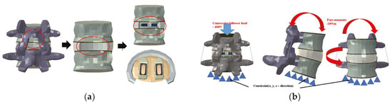
Figure 4.
(a) Implementation of lumbar treatment model, (b) Physiological loading applied to the developed lumbar treatment model.
To implement the physiological loading conditions, the tide-contact conditions were applied to contact surfaces between bone and all surgical instruments in order to achieve a perfect bone fusion, as shown in Figure 4. A 400 N compressive follower pre-load and a 10 Nm pure moment were applied to the L4 superior endplate, and the L5 inferior endplate was constrained to prevent displacement in all directions. After applying a force of flexion/extension (10 Nm), axial rotation (10 Nm), and lateral bending (5 Nm), respectively, the results were evaluated (Figure 4b). The maximum stress of the cancellous bone of the cage and vertebral body interface were compared and analyzed after each motion, and the analysis was performed using ABAQUS/Standard V 6.10 (Simulia Corp, Providence, RI, USA), a commercial finite element analysis software.
2.4. Verification of Manufactured Prototype
Static compression shear static torsion test, and static torsion test were performed in order to identify the possible movements in the human spine, and a dynamic compression test was performed to confirm the problems caused by the cyclic loading, referencing ASTM-F2077, an international standard of the spinal fusion cage. In order to identify the likelihood of subsidence of the fabricated prototype, a subsidence test was performed with reference to international standard ASTM F2267, and an MTS 858 Bionix (MTS System Corp, Eden Prairie, MN, USA) was used for the mechanical load. To compare the performance with the fusion cage, commercial PEEK materials were compared with the fusion cage (LP Cage, Medyssey, Chungcheongbuk-do, Korea) and titanium alloy material fusion cage (LT Cage, Medyssey, Chungcheongbuk-do, Korea). For accurate comparison, the lengths and widths of all three products were kept consistent, and both of the selected fusion cages were approved by the Korean Food and Drug Administration and the US FDA 510K. Their results were normalized with the composite fusion cage and compared.
The jig was designed to transfer the force to the fusion cage according to the standards of ASTM F2077 and F2267. The jig was designed and manufactured for compression, torsion, subsidence and shear according to the direction of each force. For each test, stainless steel was used for the static test, poly acetal was used for the dynamic test, and PU (Polyurethane) foam material was used for the subsidence test (Figure 5).
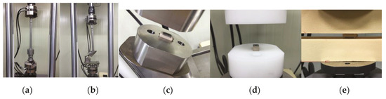
Figure 5.
Test jig and test block: (a) test jig for compression, torsion and subsidence, (b) test jig for compression shear, (c) test block for static compression and compression shear, torsion, (d) test block dynamic compression, (e) test block for subsidence.
Static compression, compression shear, and subsidence tests were performed six times and averaged by applying loads (load, N) and displacement at a rate of 25 mm/min to obtain the data. Torsional strength (torque, Nm) and angle (angle, degree) were obtained by applying static torsion at a rate of 60 degrees/min, and the measurement was conducted six times to obtain data, and data were averaged. In the dynamic compression test, the R-ratio was set at 10% and 5,000,000 cycles were tested at a frequency of 5 Hz. The applied load was determined by the static compression load value, and the applied load was decreased step by step. Fracture and deformation were confirmed [14,15].
3. Results
3.1. Verification of Porosity Size
The result was 465 µm when the spacing was 1.0 mm, 535 µm when the spacing was 1.2 mm, 660 µm when the spacing was 1.4mm, 805µm when the spacing was 1.6 mm, and 955 µm when the spacing was 1.8 mm (Figure 6). As a result, the SEM measurement showed that 1.2 mm was closest to the cancellous bone.
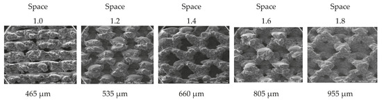
Figure 6.
SEM measurement result by porous size.
3.2. Verification of Porous Structure Fusion Strength by Type
Push down strength results for the additive manufactured porous structure samples Type 1, Type 2, and Type 3 were 157.95 N, 182.38 N, 202.89 N and 133.73 N, respectively. The result for solid structure sample was 133.73 N. The sample with the simple bar machining was recorded at 21.16 N, indicating that the sample was immediately dislocated when the push down load was applied, and thus had no bone fusion that was observed (Figure 7). All of the specimens produced with additive manufacturing showed better push down strength than the specimens prepared by machining, and Type 3 had the highest push down strength.
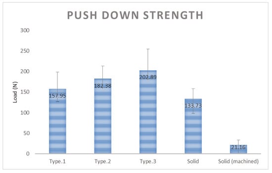
Figure 7.
Comparison of push down strength result by sample type.
3.3. Likelihood of Subsidence of Intervertebral Fusion Cage
In comparison of the likelihood of subsidence according to each motion of the two types of cages, in the flexion motion, non-porous and porous cages were about 490% and 210%, respectively, showing that the non-porous cage had about a 2.33 times higher likelihood than the porous cage (Figure 8a). In the extension motion, the values were about 210% and 180%, respectively, showing that the non-porous had about a 1.16 times higher likelihood (Figure 8b). In the axial rotation motion, those values were about 90% and 46%, showing that the porous cage had about a 1.9 higher likelihood (Figure 8c), and in the lateral bending motion, those values were about 100% and 55%, showing that the porous cage had about a 1.81 higher likelihood (Figure 8d).
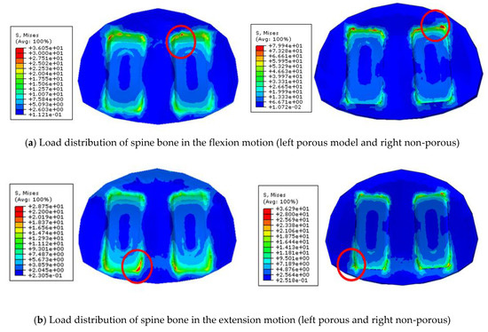
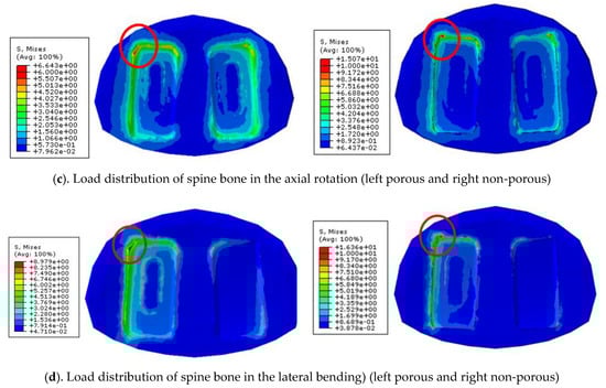
Figure 8.
Load distribution of spine bone in the various motions
In all movements, it was confirmed that the likelihood of subsidence is lower in the cage with the porous structure than that of the non-porous cage. It can be seen that interface with porous structure significantly lowers interfacial stress and shows low subsidence likelihood.
3.4. Verification of Cage Prototype Performance
Static compression test results in comparison of the composite cage with the commercial PEEK cage and titanium cage showed 78% and 159% in Yield load, and 86% and 136% in stiffness, respectively. Static compression shear test results in comparison to the composite cage with the commercial PEEK and titanium cage showed 83% and 154% in yield load, and 81% and 207% in stiffness, respectively. Static torsion test results in comparison to the composite cage with the commercial PEEK and titanium cage showed 66% and 138% in yield torque, and 76% and 169% in stiffness, respectively (Figure 9). Static subsidence test results in comparison to the composite cage with the commercial PEEK and titanium cage showed 103% and 61% in yield torque, and 95% and 61% in stiffness, respectively (Figure 10).
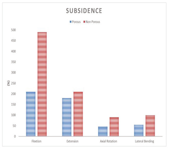
Figure 9.
Comparison of subsidence likelihood in each motion.
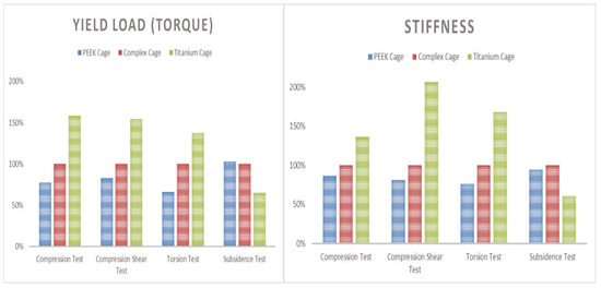
Figure 10.
Average result of performance test (left yield load and right stiffness).
The dynamic compression test of the composite fusion cage confirmed the collapse of the titanium grains in the porous cover at 51,000 cycles at a load of 12,000 N and 2,401,500 cycles at a load of 8000 N. However, no change was observed in the porous composite cage after 5,000,000 cycles at a load of 6000 N.
4. Discussion
In the push down test, all of the specimens produced with additive manufacturing showed better push down strength than the specimens prepared by machining, and Type 3 had the highest push down strength, and therefore has the best bone fusion strength. Specimens made with machining had smoother surfaces, which led to a larger surface area and thus an excellent fusion strength, while those made with additive manufacturing had a rougher surface area. As a result, the Type 3 structure showed the best bone fusion strength.
The sample coated with a porous coating on PEEK surface showed the following push down testing results: 2.5 times in 0 weeks, 6 times in 12 weeks and 10 times in 24 weeks, which are higher results in comparison to the samples without coating, and which is similar to our research result [16].
The analysis of the potential sedimentation in FEM method according to the titanium and the PEEK materials studied by Chiang show that the amount is 1.6 times higher for flexibility, 1.5 times higher for extension and 1.4 times higher for material bending, so the titanium material is considered more vulnerable than PEEK in all exercises [17]. This is similar result to our findings.
In the study on compressive strength according to the porosity of titanium material studied by Junchao, it is reported that as the porosity grows, the elastic rate increases; and if the porosity increases about two times then the elasticity increases 1.7 times [18]. The titanium materials in our porosity can be identified with similar results from our study that have high elasticity to reduce subsidence.
In the cage prototype test of mechanical performance, the porous composite fusion cage showed better results than the commercial PEEK cage, although it showed lower results than all commercial PEEK cages in static compression, static compression shear and torsion tests. In the subsidence test, it showed better results than the commercial titanium cage and showed similar results to the commercial PEEK cage. In the compression fatigue test, there was no change or breakage in the cage after 6000 N to 5,000,000 cycles. The compressive load threshold value of human Lumbar static FSU (Functional Spinal Unit) are known to be 5000 to 8500 N and the cancellous bone strength is known to be 2000 N [19,20,21,22]. Therefore, the results obtained at 6000 N were similar to those of human static FSU, and the composite fusion cage was considered structurally stable, since it sustained 5,000,000 cycles under the load, which is about 3 times higher than the cancellous strength.
In all static compression, compression shear and torsion test results, the commercial titanium cage showed the highest yield load and stiffness results and the commercial PEEK cage showed the lowest results. However, in the subsidence test, the commercial PEEK cage showed the highest results. These results are thought to be because of the difference of material property elasticity of titanium and PEEK, rather than the difference of design.
As a result, because the porous composite cage showed better or similar results compared with both commercial cages, that were approved by the Korean Food and Drug Administration and FDA 510 K and which have been used for many years without any problems, it is concluded that the porous composite cage has sufficient performance results for clinical use [23,24].
5. Conclusions
In this study, the correlation between the bone fusion and the porous structure and size of the spine fusion cage composing the composite for porous structure and elasticity was confirmed. Type 3 structures showed the best bone fusion and the pore size of 1.2 mm was most suitable. In addition, the likelihood of subsidence of a cage with a porous structure is considered to be lower than that of a cage with a solid structure. When the new composite cage combined with two composites was compared and verified with commercial products, the performance was better than that of the existing PEEK material. The subsidence result was superior to the titanium product and showed similar results to PEEK products. Thus, it is possible to completely replace existing PEEK products performance-wise. However, although all results are similar or excellent, it is considered that clinical studies should be further conducted to confirm the result of additional bone-fusion rate and subsidence, because this study was only conducted at the in vitro level.
Author Contributions
Conceptualization, K.-M.L.; methodology, K.-M.L.; software, K.-M.L. and T.-H.P.; validation, K.-M.L. and T.-H.P.; formal analysis, K.-M.L. and T.-H.P.; investigation, K.-M.L.; data curation, K.-M.L. and T.-H.P.; writing (original draft preparation), K.-M.L.; writing (review and editing), S.-J.L. and S.-J.P.; visualization, K.-M.L.; supervision, S.-J.L. and S.-J.P.; project administration, S.-J.P.
Funding
This work was supported by the Technology Development Program(S2296780) funded by the Ministry of SMEs and Startups (MSS, Korea).
Conflicts of Interest
The authors declare no conflict of interest.
References
- Oh, K.W.; Lee, J.H.; Lee, J.H.; Lee, D.Y.; Shim, H.J. The correlation between cage subsidence, bone mineral density, and clinical results in posterior lumbar interbody fusion. Clin. Spine Surg. 2017, 30, E683–E689. [Google Scholar] [CrossRef] [PubMed]
- Park, Y.; Ha, J.W. Comparison of one-level posterior lumbar interbody fusion performed with a minimally invasive approach or a traditional open approach. Spine 2007, 32, 537–543. [Google Scholar] [CrossRef] [PubMed]
- Steffee, A.D.; Sitkowski, D.J. Posterior Lumbar Interbody Fusion and Plates. Clin. Orthop. Relat. Res. 1988, 227, 102. [Google Scholar] [CrossRef]
- Green, S.; Schlegel, J. A polyaryletherketone biomaterial for use in medical implant applications. Polym. Med. Ind. Proc. 2015, 5, 1–9. [Google Scholar]
- Cabraja, M.; Oezdemir, S.; Koeppen, D.; Kroppenstedt, S. Anterior cervical discectomy and fusion: comparison of titanium and polyetheretherketone cages. BMC Musculoskelet. Disord. 2012, 13, 172. [Google Scholar] [CrossRef] [PubMed]
- Yook, S.W.; Kim, H.E.; Koh, Y.H. Fabrication of porous titanium scaffolds with high compressive strength using camphene-based freeze casting. Mater. Lett. 2009, 63, 1502–1504. [Google Scholar] [CrossRef]
- Wu, G.M.; Hsiao, W.D.; Kung, S.F. Investigation of hydroxyapatite coated polyether ether ketone composites by gas plasma sprays. Surf. Coat. Technol. 2009, 203, 2755–2758. [Google Scholar] [CrossRef]
- Shirazi-Adl, S.A.; Shrivastava, S.C.; Ahmed, A.M. Stress Analysis of the Lumbar Disc-Body Unit in Compression A Three-Dimensional Nonlinear Finite Element Study. Spine 1984, 9, 120–134. [Google Scholar] [CrossRef] [PubMed]
- Han, C.-M.; Lee, E.-J.; Kim, H.-E.; Koh, Y.-H.; Kim, K.N.; Ha, Y.; Kuh, S.-U. The electron beam deposition of titanium on polyetheretherketone (PEEK) and the resulting enhanced biological properties. Biomaterials 2010, 31, 3465–3470. [Google Scholar] [CrossRef] [PubMed]
- Yoon, B.H.; Kim, H.E. Development and perspective of biomaterials for spinal fusion. Korean J. Spine 2010, 7, 221–227. [Google Scholar]
- Elias, C.N.; Lima, J.H.C.; Valiev, R.; Meyers, M.A. Biomedical applications of titanium and its alloys. J. Miner. Met. Mater. Soc. 2008, 60, 46–49. [Google Scholar] [CrossRef]
- Vu, N.B.; Truong, N.H.; Dang, L.T.; Phi, L.T.; Ho NT, T.; Pham, T.N.; Van Pham, P. In vitro and in vivo biocompatibility of Ti-6Al-4V titanium alloy and UHMWPE polymer for total hip replacement. Biomed. Res. Ther. 2016, 3, 567–577. [Google Scholar] [CrossRef]
- Chen, W.-M.; Park, C.; Lee, K.; Lee, S. In Situ Contact Analysis of the Prosthesis Components of Prodisc-L in Lumbar Spine Following Total Disc Replacement. Spine 2009, 34, E716–E723. [Google Scholar] [CrossRef] [PubMed]
- ASTM F2077-18. Test Methods for Intervertebral Body Fusion Devices; ASTM International: West Conshohocken, PA, USA, 2018. [Google Scholar]
- ASTM F2267-04. Standard Test Method for Measuring Load Induced Subsidence of Intervertebral Body Fusion Device Under Static Axial Compression; ASTM International: West Conshohocken, PA, USA, 2018. [Google Scholar]
- Cheng, B.C.; Koduri, S.; Wing, C.A.; Woolery, N.; Cook, D.J.; Spiro, R.C. Porous titanium-coated polyetheretherketone implants exhibit an improved bone–implant interface: an in vitro and in vivo biochemical, biomechanical, and histological study. Med. Devices 2018, 11, 391–402. [Google Scholar] [CrossRef] [PubMed]
- Chiang, M.F.; Teng, J.M.; Huang, C.H.; Cheng, C.K.; Chen, C.S.; Chang, T.K.; Chao, S.H. Finite element analysis of cage subsidence in cervical interbody fusion. J. Med. Biol. Eng. 2004, 24, 201–208. [Google Scholar]
- Junchao, L.; Yanyan, Z.; Wei, W. Elastic modulus and stress analysis of porous titanium parts fabricated by selective laser melting. J. Harbin Inst. Technol. 2016, 23, 46–50. [Google Scholar] [CrossRef]
- Panjabi, M.M. Hybrid multidirectional test method to evaluate spinal adjacent-level effects. Clin. Biomech. 2007, 22, 257–265. [Google Scholar] [CrossRef] [PubMed]
- Rohlmann, A.; Bauer, L.; Zander, T.; Bergmann, G.; Wilke, H.-J. Determination of trunk muscle forces for flexion and extension by using a validated finite element model of the lumbar spine and measured in vivo data. J. Biomech. 2006, 39, 981–989. [Google Scholar] [CrossRef] [PubMed]
- White, A.; Panjabi, M.M. Clinical Biomechanics of the Spine, 2nd ed.; JB Lippincott Co.: Philadelphia, PA, USA, 1990. [Google Scholar]
- Polikeit, A.; Ferguson, S.J.; Nolte, L.P.; Orr, T.E. Factors influencing stresses in the lumbar spine after the insertion of intervertebral cages: finite element analysis. Eur. Spine J. 2003, 12, 413–420. [Google Scholar] [CrossRef] [PubMed]
- Hench, L.L.; Wilson, J. An Introduction to Bioceramics.; Hench, L.L., Wilson, J., Eds.; World Scientific: Singapore, 1993. [Google Scholar]
- Pollintine, P.; Dolan, P.; Tobias, J.H.; Adams, M.A. Intervertebral Disc Degeneration Can Lead to “Stress-Shielding” of the Anterior Vertebral Body. Spine 2004, 29, 774–782. [Google Scholar] [CrossRef] [PubMed]
© 2019 by the authors. Licensee MDPI, Basel, Switzerland. This article is an open access article distributed under the terms and conditions of the Creative Commons Attribution (CC BY) license (http://creativecommons.org/licenses/by/4.0/).