Sustainable Management of the Plastic-Rich Fraction of WEEE by Utilization as a Reducing Agent in Metallurgical Processes


Abstract
:Featured Application
Abstract
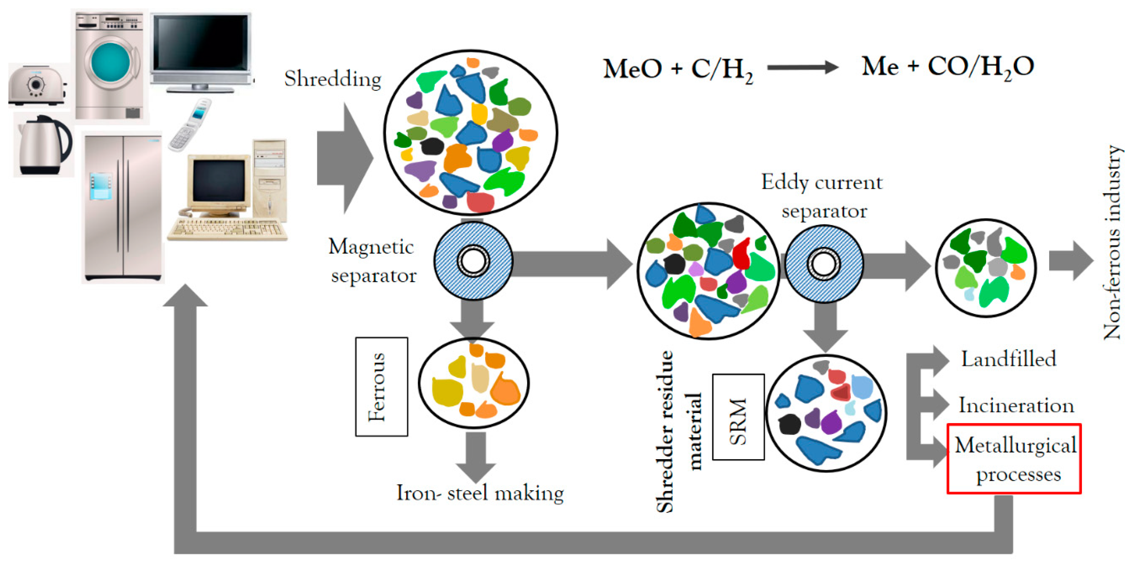
1. Introduction
2. Materials and Methods
2.1. Conversion Characteristics under Oxidizing Conditions
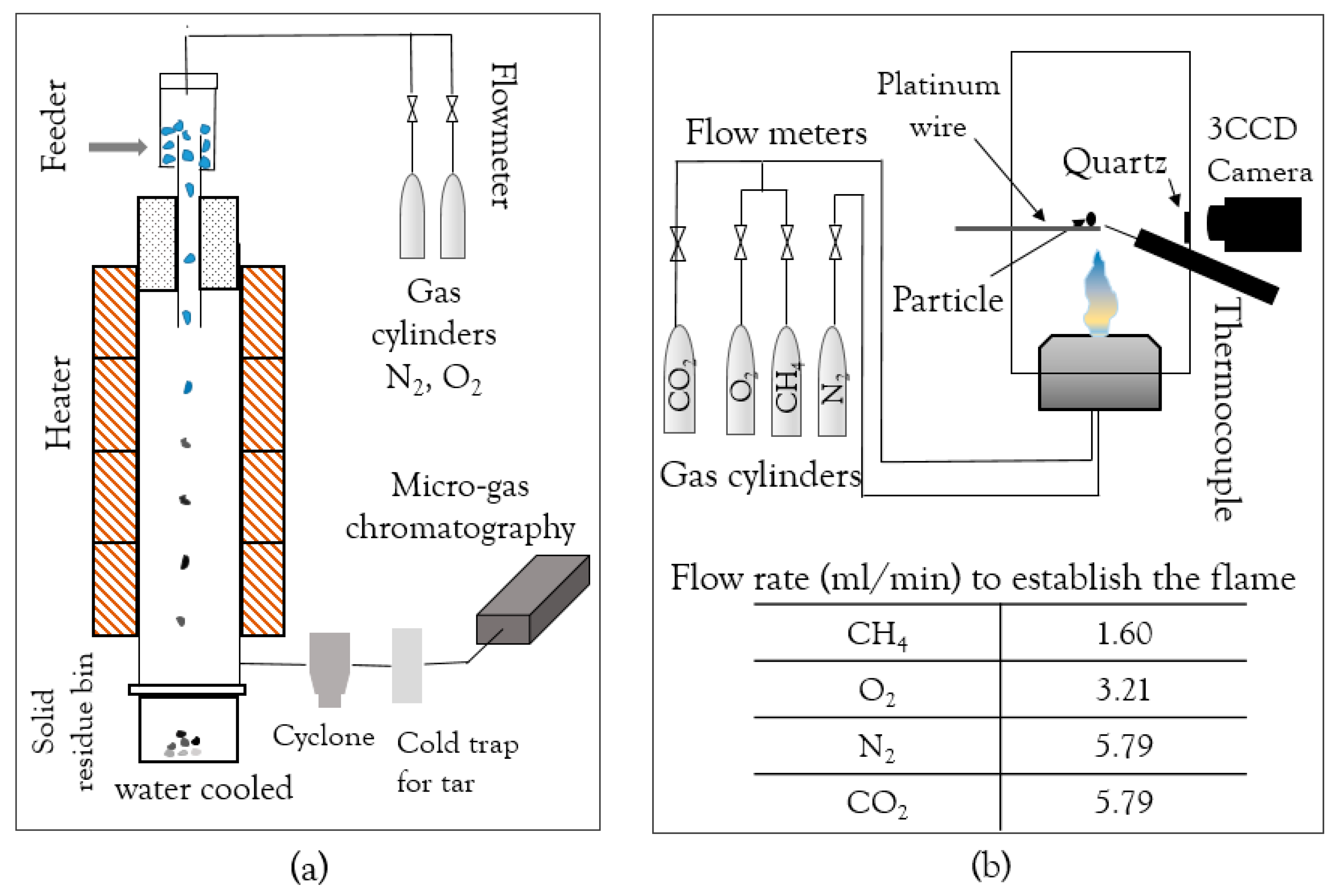
2.1.1. Drop Tube Furnace (DTF)
2.1.2. Optical Single-Particle Burner (OSB)
2.2. Industrial Trial
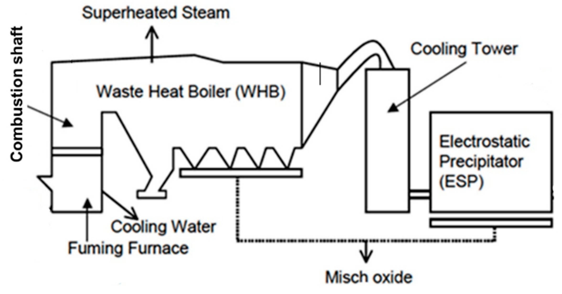
2.2.1. Description of the Zinc Fuming Process in Boliden Rönnskär
2.2.2. Experimental Design and Sampling
3. Results
3.1. Conversion under Oxidizing Conditions
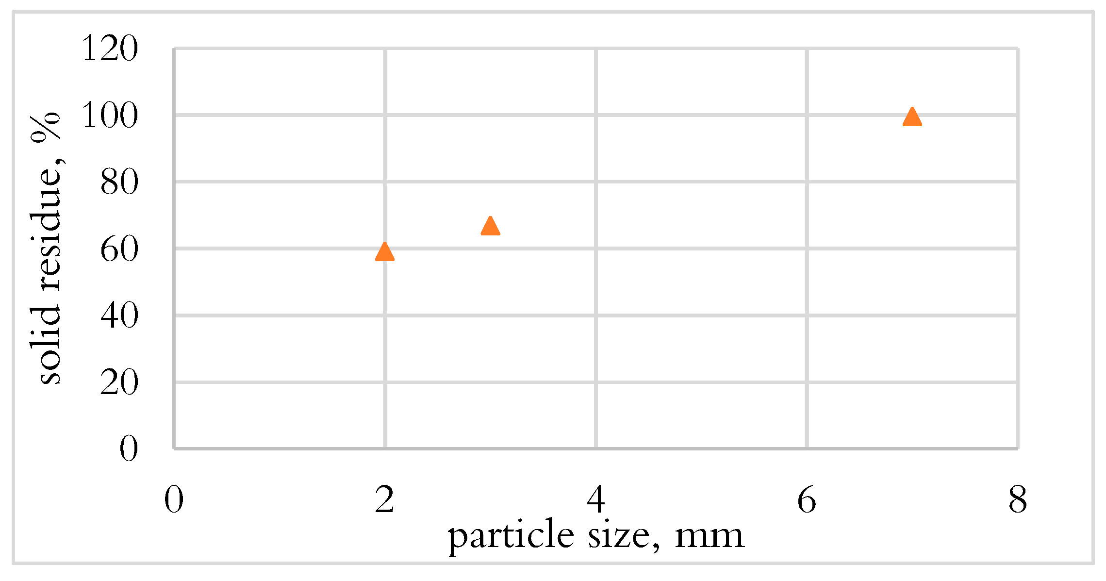
3.1.1. Effect of Particle Size on Conversion in DTF
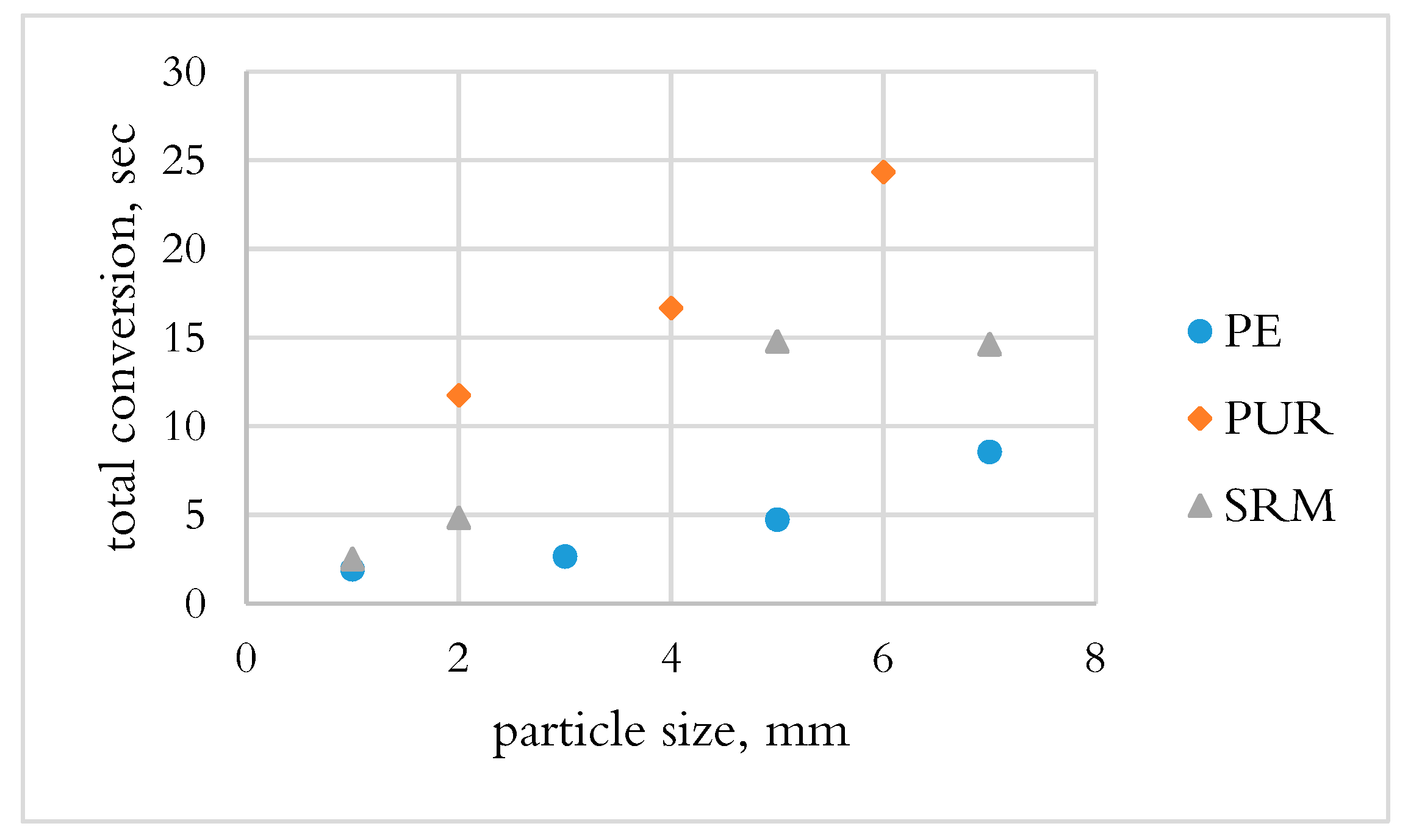
3.1.2. Determination of Total Conversion Time by OSB
3.2. Industrial Trial Result
4. Discussion
5. Conclusions
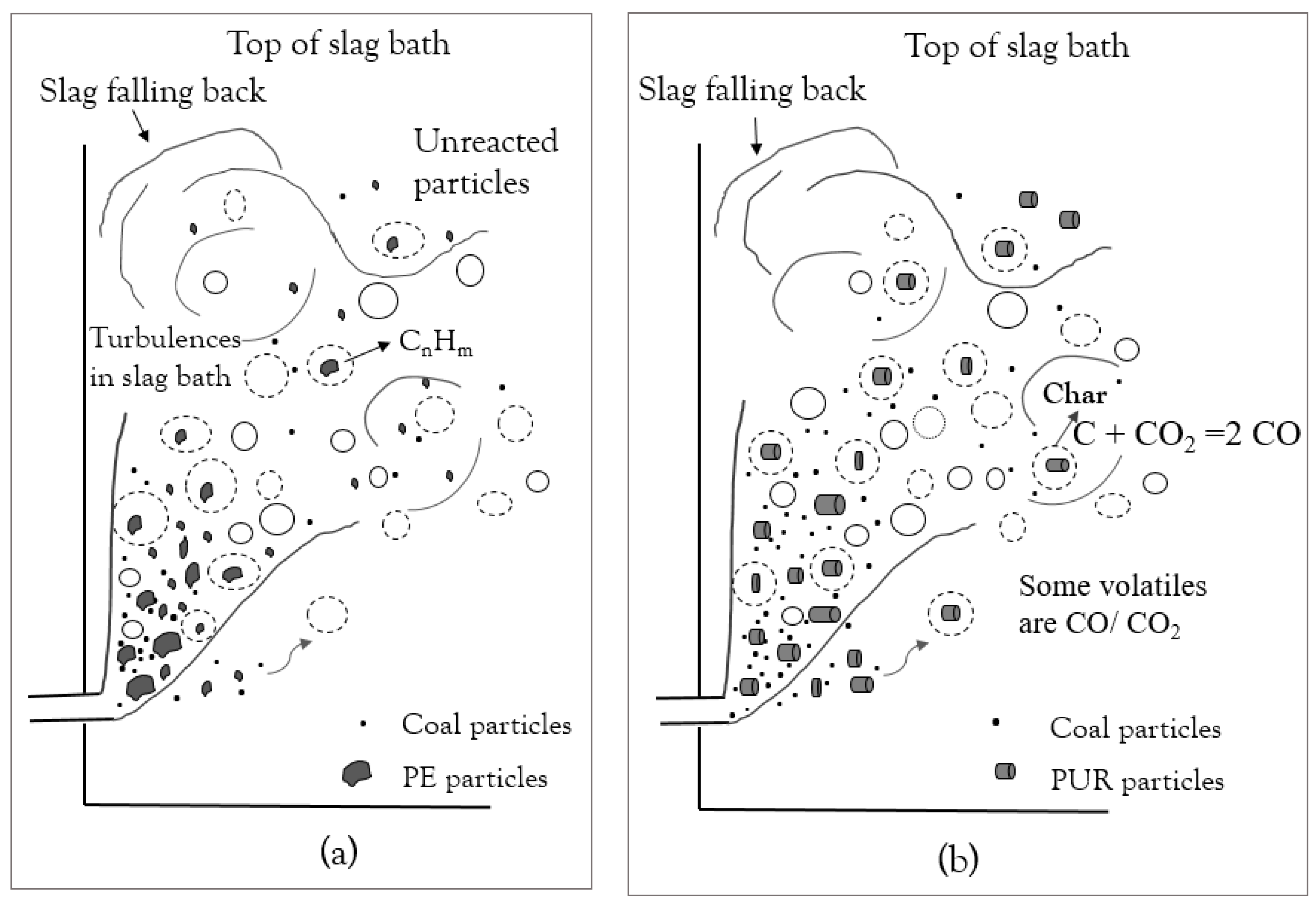
- PE and PUR were not converted during the DTF test, which could be due to the fast drop of materials and the heat transfer mechanism.
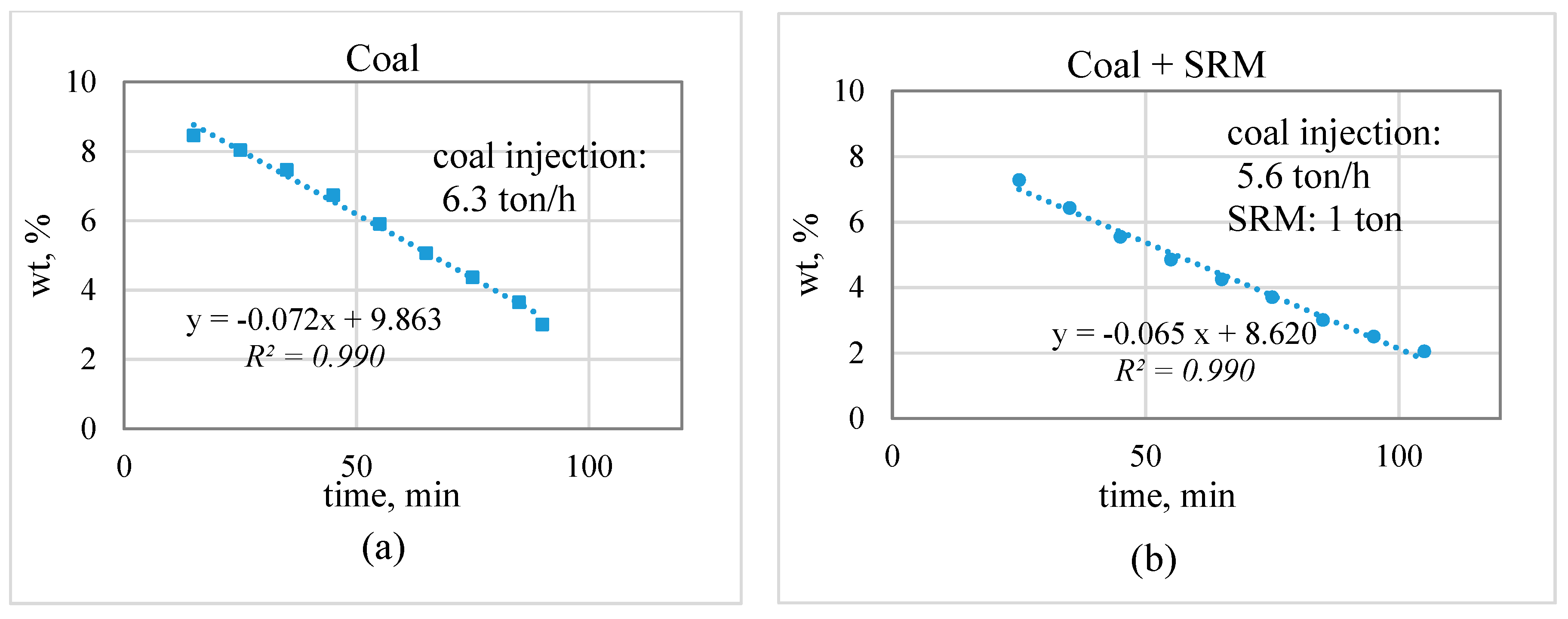
- The zinc concentration in the slag bath decreased linearly over time; the slope indicates the zinc reduction rate. The decrease in the coal injection and substitution with plastic-containing materials did not lead to a significant decrease in the zinc reduction rate. This suggests the possibility of partially substituting for coal with plastic materials.
- Steam generation increased during the trial with co-injection of plastic materials. The increase in steam generation suggests that part of the plastic material injected did not participate in reactions in the slag bath and went to post-combustion.
- Generation of reducing gases such as CO and H2 and their residence time in the slag bath are the important parameters in the efficiency of the reductant.
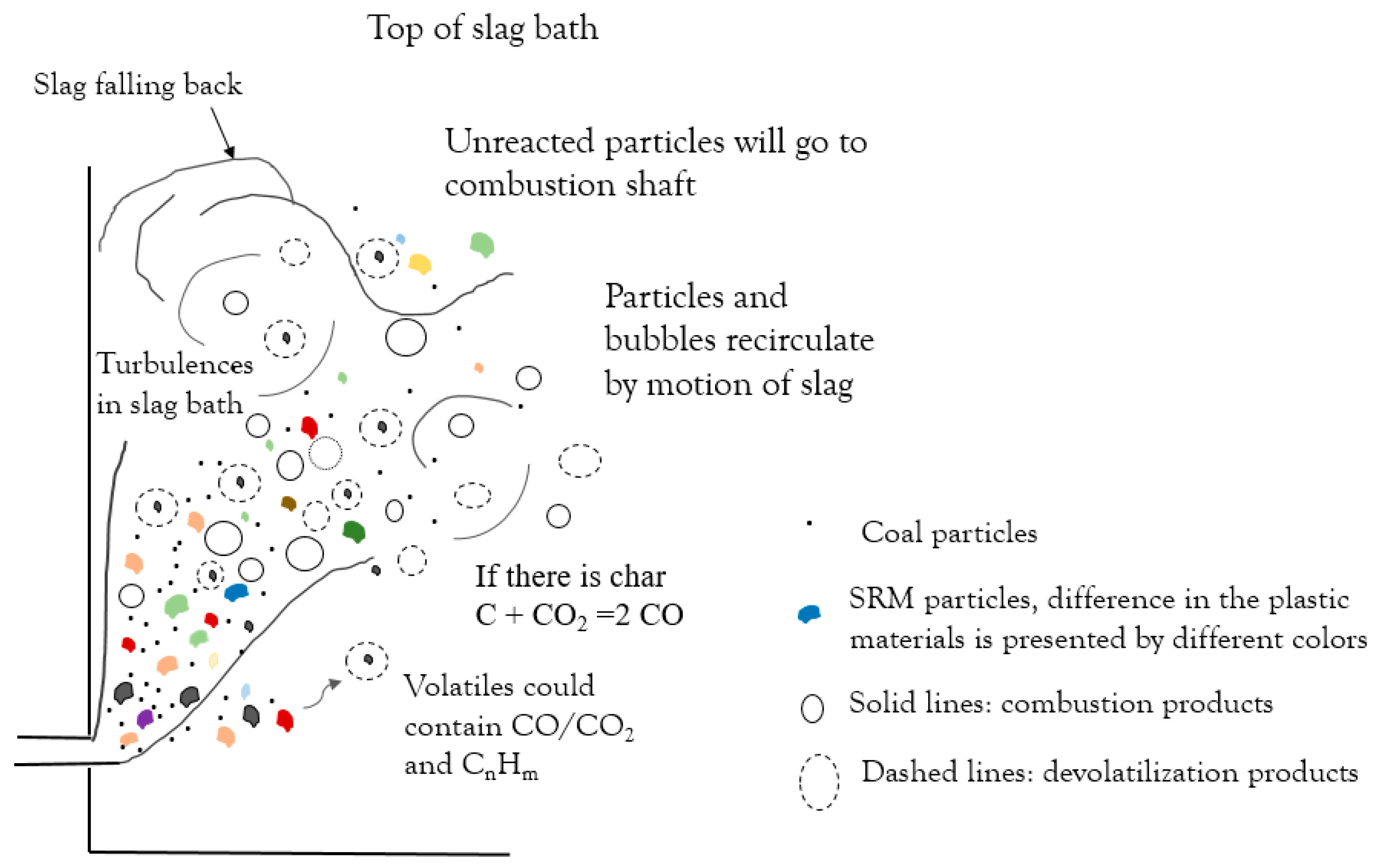
- PE had the shortest conversion time; however, the volatiles released only consisted of hydrocarbons, which require a long time to decompose. PUR and SRM in the slag bath had the possibility to convert by the reaction of fixed carbon in char.
Author Contributions
Funding
Acknowledgments
Conflicts of Interest
References
- Buekens, A.; Yang, J. Recycling of WEEE plastics: A review. J. Mater. Cycles Waste Manag. 2014, 16, 415–434. [Google Scholar] [CrossRef]
- Yang, X.; Sun, L.; Xiang, J.; Hu, S.; Su, S. Pyrolysis and dehalogenation of plastics from waste electrical and electronic equipment (WEEE): A review. Waste Manag. 2013, 33, 462–473. [Google Scholar] [CrossRef] [PubMed]
- Statista. Forecast of Per Capita Electronic Waste Generation Worldwide from 2010 to 2018 (In Kilograms Per Capita). Available online: https://www.statista.com/ (accessed on 12 October 2018).
- Isernia, R.; Passaro, R.; Quinto, I.; Thomas, A. The Reverse Supply Chain of the E-Waste Management Processes in a Circular Economy Framework: Evidence from Italy. Sustainability 2019, 11, 2430. [Google Scholar] [CrossRef]
- Gramatyka, P.; Nowosielski, R.; Sakiewicz, P. Recycling of waste electrical and electronic equipment. J. Achiev. Mater. Manuf. Eng. 2007, 20, 535–538. [Google Scholar]
- Tostar, S. Mechanical and Thermal Properties of Recycled WEEE Plastic Blends. Ph.D. Thesis, Chalmers University of Technology, Gothenburg, Sweden, 2016. [Google Scholar]
- Responsible Recycling of WEEE Plastics Containing Brominated Flame Retardants- BFR’s. Available online: www.eera-recyclers.com (accessed on 16 December 2018).
- Menad, N.; Björkman, B.; Allain, E.G. Combustion of plastics contained in electric and electronic scrap. Resour. Conserv. Recycl. 1998, 24, 65–85. [Google Scholar] [CrossRef]
- Rosi, L.; Bartoli, M.; Frediani, M. Microwave assisted pyrolysis of halogenated plastics recovered from waste computers. Waste Manag. 2018, 73, 511–522. [Google Scholar] [CrossRef] [PubMed]
- Evangelopoulos, P. Pyrolysis and Detoxification of Waste Electrical and Electronic Equipment (WEEE) for Feedstock Recycling. Ph.D. Thesis, KTH Royal Institute of Technology, Stockholm, Sweden, 2018. [Google Scholar]
- Sahajwalla, V.; Zaharia, M.; Kongkarat, S.; Khanna, R.; Saha-Chaudhury, N.; O’Kane, P. Recycling plastics as a resource for electric arc furnace (EAF) steelmaking: Combustion and structural transformations of metallurgical coke and plastic blends. Energy Fuels 2009, 24, 379–391. [Google Scholar] [CrossRef]
- Waladan, M.; Nilmani, M. The Effect of Injection Parameters on Slag Fuming. Can. Metall. Q. 1995, 34, 311–318. [Google Scholar] [CrossRef]
- Asanuma, M.; Ariyama, T.; Sato, M.; Murai, R.; Nonaka, T.; Okochi, I.; Tsukiji, H.; Nemoto, K. Development of Waste Plastics Injection Process in Blast Furnace. ISIJ Int. 2000, 40, 244–251. [Google Scholar] [CrossRef]
- Dankwah, J.R.; Koshy, P.; Saha-Chaudhury, N.M.; O’Kane, P.; Skidmore, C.; Knights, D.; Sahajwalla, V. Reduction of FeO in EAF steelmaking slag by metallurgical coke and waste plastics blends. ISIJ Int. 2011, 51, 498–507. [Google Scholar] [CrossRef]
- Bodénan, F.; Menad, N.; Wavrer, P.; Guignot, S.; Quatravaux, T.; Russo, P. Recycling of automotive shredder residues (ASR) in iron- and steelmaking furnaces. Ironmak. Steelmak. 2012, 39, 493–497. [Google Scholar] [CrossRef]
- Brusselaers, J.; Mark, F.E.; Tange, L. Using Metal-Rich WEEE Plastics as Feedstock/Fuel Substitute for an Integrated Metals Smelter; Technical Report; Plastics Europe: Brussels, Belgium, 2006. [Google Scholar]
- Lotfian, S.; Ahmed, H.; Umeki, K.; Samuelsson, C. Conversion Characteristics of Alternative Reducing Agents for the Bath Smelting Processes in an Oxidizing Atmosphere. J. Sustain. Metall. 2019, 5, 230–239. [Google Scholar] [CrossRef]
- Umeki, K.; Häggström, G.; Bach-Oller, A.; Kirtania, K.; Furusjö, E. Reduction of Tar and Soot Formation from Entrained-Flow Gasification of Woody Biomass by Alkali Impregnation. Energy Fuels 2017, 31, 5104–5110. [Google Scholar] [CrossRef]
- Bach-Oller, A.; Furusjö, E.; Umeki, K. Fuel conversion characteristics of black liquor and pyrolysis oil mixtures: Efficient gasification with inherent catalyst. Biomass Bioenergy 2015, 79, 155–165. [Google Scholar] [CrossRef]
- Borell, M. Slag-a resource in the sustainable society. In Proceedings of the Securing the Future, International Conference, Mining and the Environmental, Metal and Energy Recovery, Skellefteå, Sweden, 27 June–1 July 2005. [Google Scholar]
- Lotfian, S.; Vikström, T.; Lennartsson, A.; Björkman, B.; Ahmed, H.; Samuelsson, C. Plastic-containing materials as alternative reductants for base metal production. Can. Metall. Q. 2019, 58, 164–176. [Google Scholar] [CrossRef]
- Almaraz, A.; López, C.; Arellano, I.; Barrón, M.A.; Jaramillo, D.; Reyes, F.; Plascencia, G. CFD modelling of fluid flow in a Peirce–Smith converter with more than one injection point. Miner. Eng. 2014, 56, 102–108. [Google Scholar] [CrossRef]
- Degerstedt, U. Injection Phenomena in the Slag-Fuming Furnace at Rönnskär Smelters. Master’s Thesis, Luleå University of Technology, Luleå, Sweden, 1987. [Google Scholar]
- Richards, G.G.; Brimacombe, J.K.; Toop, G.W. Kinetics of the zinc slag-Fuming process: Part i. industrial measurements. Metall. Mater. Trans. A 1985, 16, 513–527. [Google Scholar] [CrossRef]
- Huda, N.; Naser, J.; Brooks, G.A.; Reuter, M.A.; Matusewicz, R.W. Computational Fluid Dynamics (CFD) Investigation of Submerged Combustion Behavior in a Tuyere Blown Slag-fuming Furnace. Metall. Mater. Trans. A 2012, 43, 1054–1068. [Google Scholar] [CrossRef]
- Lehner, T.; Lindgren, R. Investigation of Fluid Flow Phenomena in Boliden’s Zinc Fuming Plant. In Proceedings of the Conference Zinc 85, Tokyo, Japan, 14–16 October 1985; pp. 185–200. [Google Scholar]
- Timothy, L.; Sarofim, A.; Beér, J. Characteristics of single particle coal combustion. Symp. Int. Combust. 1982, 19, 1123–1130. [Google Scholar] [CrossRef]
- Lotfian, S.; Ahmed, H.; Samuelsson, C. Alternative reducing agents in metallurgical processes: Devolatilization of shredder residue materials. J. Sustain. Metall. 2017, 3, 311–321. [Google Scholar] [CrossRef]
- Ward, D.H. Rate Limitation of the Slag Fuming Process. In International Congress on Mineral Processing and Extractive Metallurgy; The Australasian Institute of Mining and Metallurgy: Minprex Melbourne, Australia, 2000; pp. 471–478. [Google Scholar]


| Ultimate Analyses | ||||||
| H (wt %) | O (wt %) | N (wt %) | S (wt %) | C (wt %) | Ash (wt %) | |
| Coal | 4.8 | 5.2 | 1.3 | 0.30 | 84.0 | 4.4 |
| SRM | 6.1 | 12.9 | 1.4 | 0.20 | 57.3 | 22.1 |
| PE | 11.6 | 1.6 | - | 0.06 | 78.5 | 8.3 |
| PUR | 6.2 | 15.3 | 6.0 | 0.03 | 61.7 | 10.8 |
| Proximate analyses | ||||||
| Moisture (wt %) | Volatile (wt %) | Fixed carbon (wt %) | Density (g/cm3) | |||
| Coal | 0.8 | 26.5 | 68.3 | 0.8 | ||
| SRM | 8.0 | 67.3 | 2.6 | 1.3 | ||
| PE | 0.3 | 89.1 | 2.3 | 0.9 | ||
| PUR | 1.6 | 80.8 | 7.1 | 1.3 | ||
| Description of Furnace | Amount and Type of Reductant during Trials | |||||||||||
|---|---|---|---|---|---|---|---|---|---|---|---|---|
| Dimension of furnace, m | 2.5 × 8 × 9 | Coal, ton/h | Plastic on average, ton | |||||||||
| Temperature of slag bath, °C | 1150–1250 °C | Coal | 6.3 | - | ||||||||
| Slag, ton | 60–90 | Coal + PE | 5.6 | 1 | ||||||||
| Air, kNm3/h | 30 | Coal + PUR | 5.6 | 3 | ||||||||
| Coal + SRM | 5.6 | 0.9 | ||||||||||
| Composition of slag bath, wt % | Al2O3 | As | CaO | Cr | Cu | Fe | MgO | Pb | S | SiO2 | Sn | Zn |
| 3.4 | 0.2 | 2.0 | 0.2 | 1.4 | 30.0 | 0.8 | 1.2 | 0.8 | 30.0 | 0.3 | 8.9 | |
| Reductant | Coal | Coal and PE | Coal and PUR | Coal and SRM |
|---|---|---|---|---|
| Average rate (wt %/min) | 0.087 | 0.064 | 0.079 | 0.063 |
| Standard deviation | 0.017 | 0.005 | 0.009 | 0.003 |
| Average rate (wt %/min)/Molar content of (C + H2) | 0.0096 | 0.0060 | 0.0064 | 0.0056 |
| Fundamental Study: Thermal Conversion Characterization | Industrial Trial: Reduction Potential | |
|---|---|---|
| Experiment | Conversion | Co-injection of plastic materials + coal |
| Equipment | Drop tube furnace‒Single particle burner | Zinc fuming furnace |
| Particle size | 1–6 mm | Less than 10 mm |
| Material tested | PE, PUR, SRM | Coal, PE, PUR, SRM |
| Highlights | PE has the shortest conversion time (only volatiles, as hydrocarbon), PUR has the longest conversion time (both volatiles and char), SRM shows a mixture of these behaviors. | It is possible to lower the coal injection rate and substitute it with plastic injection; steam generation increased, which suggested that part of the plastic goes to gas phase. |
| The conversion characteristic helps in understanding the plastic materials in the fuming process; parameters such as conversion time and product plays an important role in the efficiency of plastic materials. | ||
© 2019 by the authors. Licensee MDPI, Basel, Switzerland. This article is an open access article distributed under the terms and conditions of the Creative Commons Attribution (CC BY) license (http://creativecommons.org/licenses/by/4.0/).
Share and Cite
Lotfian, S.; Lennartsson, A.; Jokilaakso, A. Sustainable Management of the Plastic-Rich Fraction of WEEE by Utilization as a Reducing Agent in Metallurgical Processes. Appl. Sci. 2019, 9, 4224. https://doi.org/10.3390/app9204224
Lotfian S, Lennartsson A, Jokilaakso A. Sustainable Management of the Plastic-Rich Fraction of WEEE by Utilization as a Reducing Agent in Metallurgical Processes. Applied Sciences. 2019; 9(20):4224. https://doi.org/10.3390/app9204224
Chicago/Turabian StyleLotfian, Samira, Andreas Lennartsson, and Ari Jokilaakso. 2019. "Sustainable Management of the Plastic-Rich Fraction of WEEE by Utilization as a Reducing Agent in Metallurgical Processes" Applied Sciences 9, no. 20: 4224. https://doi.org/10.3390/app9204224
APA StyleLotfian, S., Lennartsson, A., & Jokilaakso, A. (2019). Sustainable Management of the Plastic-Rich Fraction of WEEE by Utilization as a Reducing Agent in Metallurgical Processes. Applied Sciences, 9(20), 4224. https://doi.org/10.3390/app9204224