1. Introduction
With the rapid development of wireless mobile communication technologies, the demand for higher data rate services has significantly increased over the recent years. The fifth-generation (5G) mobile communication system [
1] was introduced and has been receiving considerable interest from various industrial fields. Among many frequency bands, the millimeter band has been considered a good candidate for 5G communication, since it provides higher data rate services because of increased channel bandwidth compared to lower frequency bands [
2]. A promising technology for utilizing millimeter band communications is the phased array antenna with beam steering capability [
3]. Most studies have focused on the high peak gain, the wide reflection coefficient bandwidth, the wide scan angle, or the low side lobe level, which are typical specifications of the phased array antenna for mobile devices [
4,
5,
6].
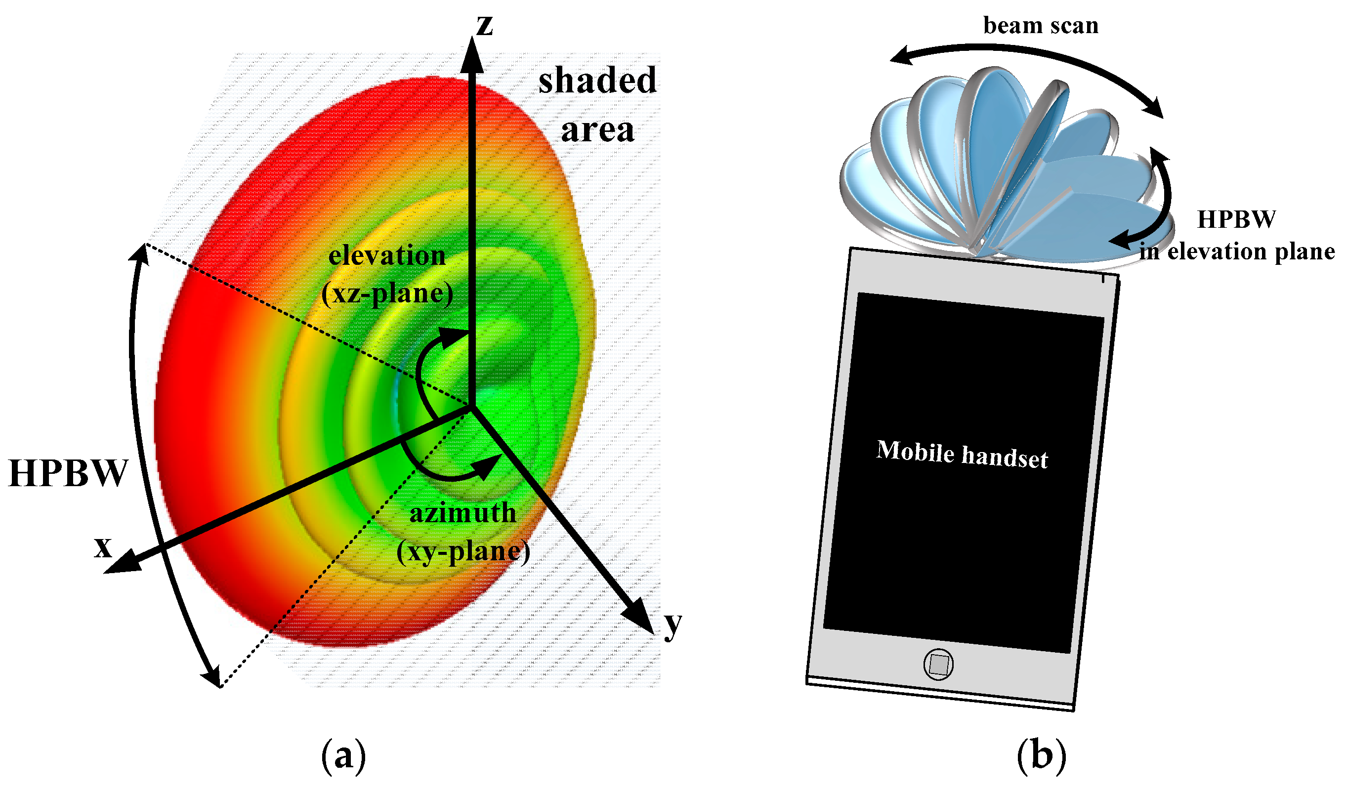
Very few, however, are interested in the half power beam width (HPBW) in the elevation plane [
7,
8,
9], which is normal to the azimuth plane (beam scanning plane), as illustrated in
Figure 1a. Since mobile communications require hemispheric beam coverage, as shown in
Figure 1b [
10], HPBW in the elevation plane (XZ plane) is a crucial specification of the phased array antenna needed to minimize the fading caused by the shaded area [
11]. The antennas proposed in [
7,
8] employ substrate-integrated waveguide structure as a cavity and used posts in order to shape the beam pattern of the antenna. The HPBWs in the elevation plane of the antennas are 133.1 degree and 180 degree, respectively. The antenna proposed in [
9] introduced parasitic loop and mushroom-like element in order to broaden the beam width up to 130 degree. However, such work either has high cost structure [
7,
8] or beam width which is not wide enough for 5G application [
9].
This paper proposes a 1 × 8 phased array antenna for 5G applications operating at 28 GHz with enhanced HPBW in the elevation plane using air-hole slots. While showing adequate performances of the reflection coefficient bandwidth, the peak gain, the scan angle, and the side lobe level [
12], the proposed antenna provides excellent HPBW in the elevation plane above 219 degree. The proposed array antenna has a relatively cost-effective structure compared with [
7,
8] and has the widest HPBW (up to 39 degree) among the three studies [
7,
8,
9,
10]. Therefore, the proposed work can play an important role as array antenna for a modern 5G mobile handset device.
2. Design of the Two-Element Antenna Array
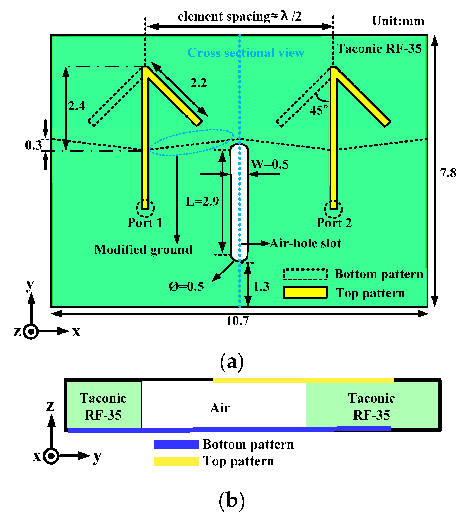
Figure 2a illustrates the structure of the proposed two-element antenna array. The proposed antenna consists of an air-hole slot in the ground substrate in addition to two bent dipole antenna elements and a modified ground. The two-element array antenna has dimensions of 10.7 mm × 7.8 mm × 0.127 mm and is printed on a Taconic RF-35 substrate with a relative permittivity of 3.5 and a loss tangent of 0.0018.
Bending of the dipole arms is applied to enhance the isolation between radiating elements and the front-to-back ratio (FBR) [
13]. In addition, the ground plane is modified to improve the impedance matching of the antenna elements [
14].
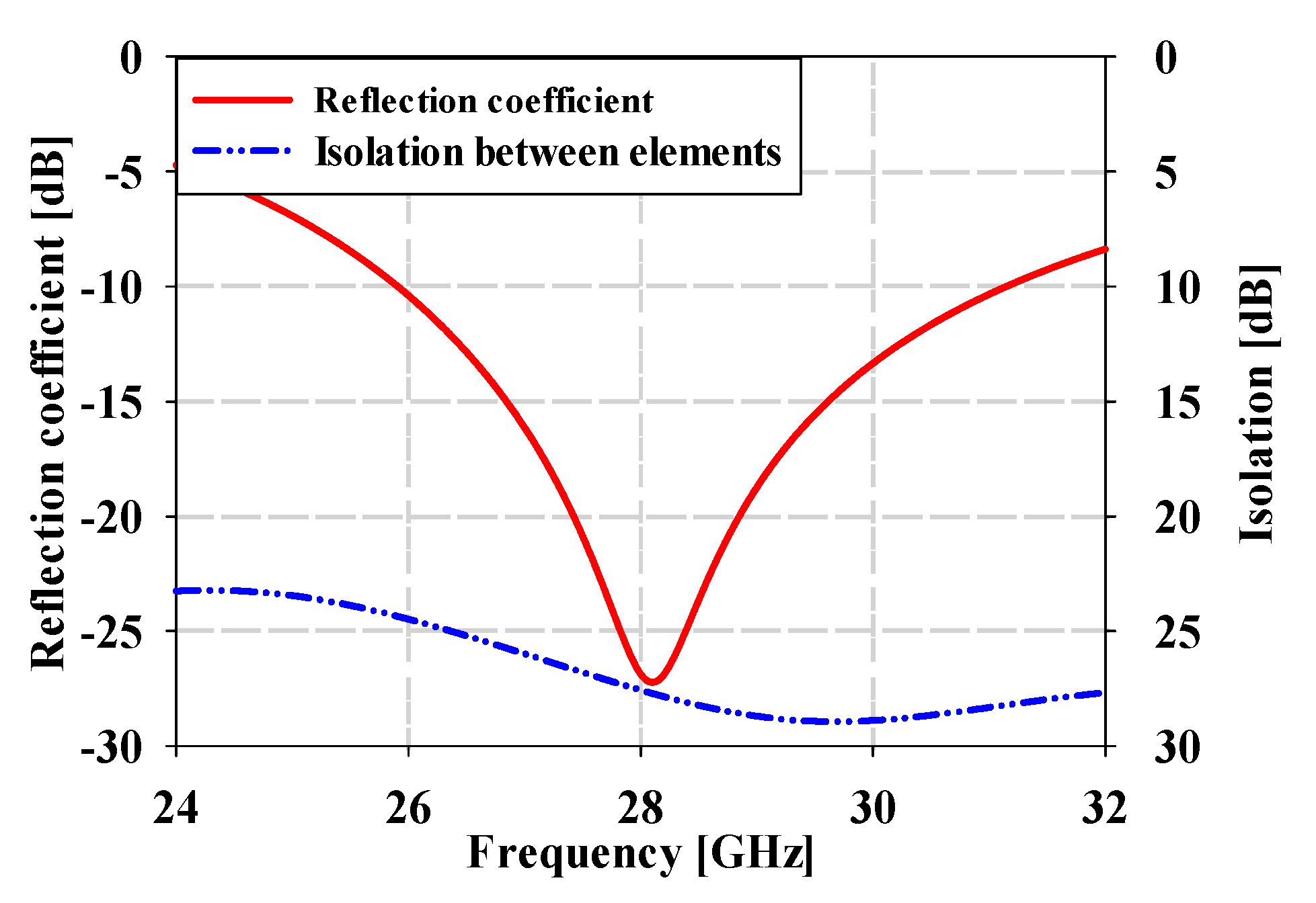
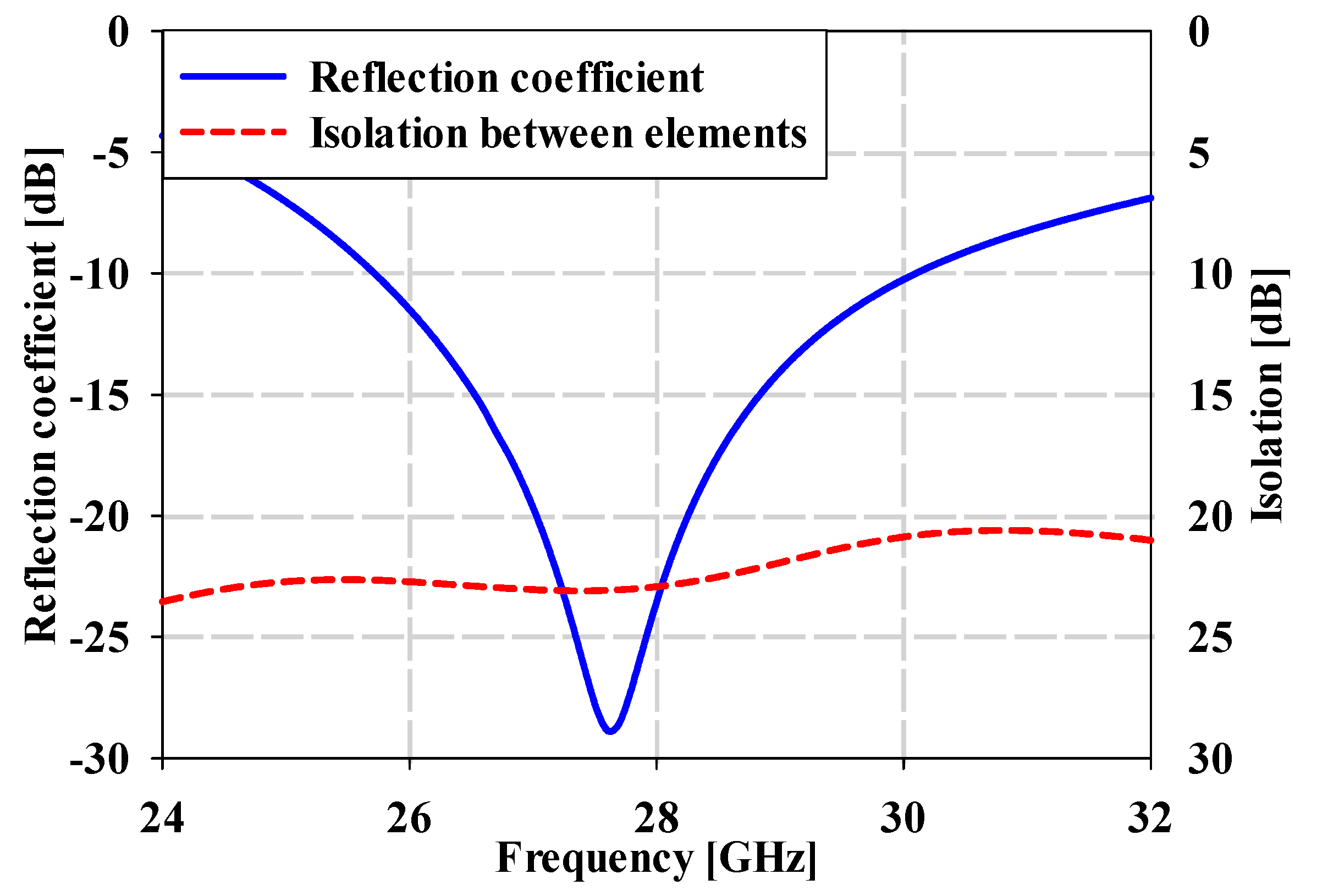
Figure 3 shows the reflection coefficient and isolation level of the proposed two-element array antenna. The proposed antenna exhibits a wide (15%) −10 dB reflection coefficient bandwidth from 25.8 GHz to 31 GHz and an excellent isolation level higher than 21 dB over the desired frequency band. A slot (an air-hole slot) in the ground substrate is introduced to create the complimentary current component necessary to obtain the wide beam width.
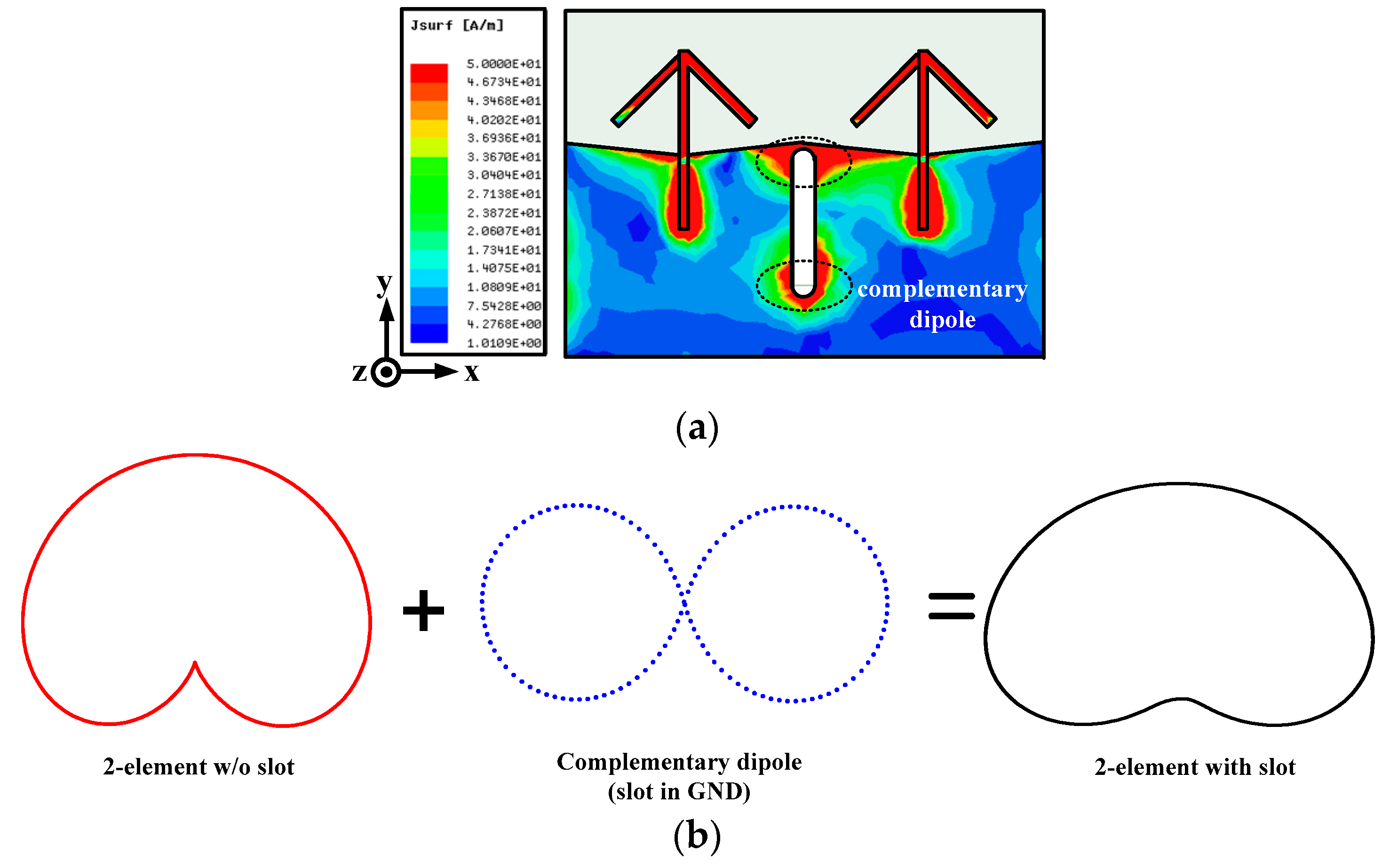
Figure 4a,b shows the operating mechanism of the proposed ground slot enhancing the HPBW in the elevation plane of the two-element array. As shown in the dotted circle in
Figure 4a, the slot in the ground with length L, approximately half of the guided wavelength, forms a complementary λ/2-dipole originating via the current distribution around the slot, as described in the following equation [
15]:
where
Therefore, the radiation pattern of the two-element dipole array is added to that of the complementary dipole from the ground slot resulting in a wider radiation pattern in the elevation plane, as shown in
Figure 4b [
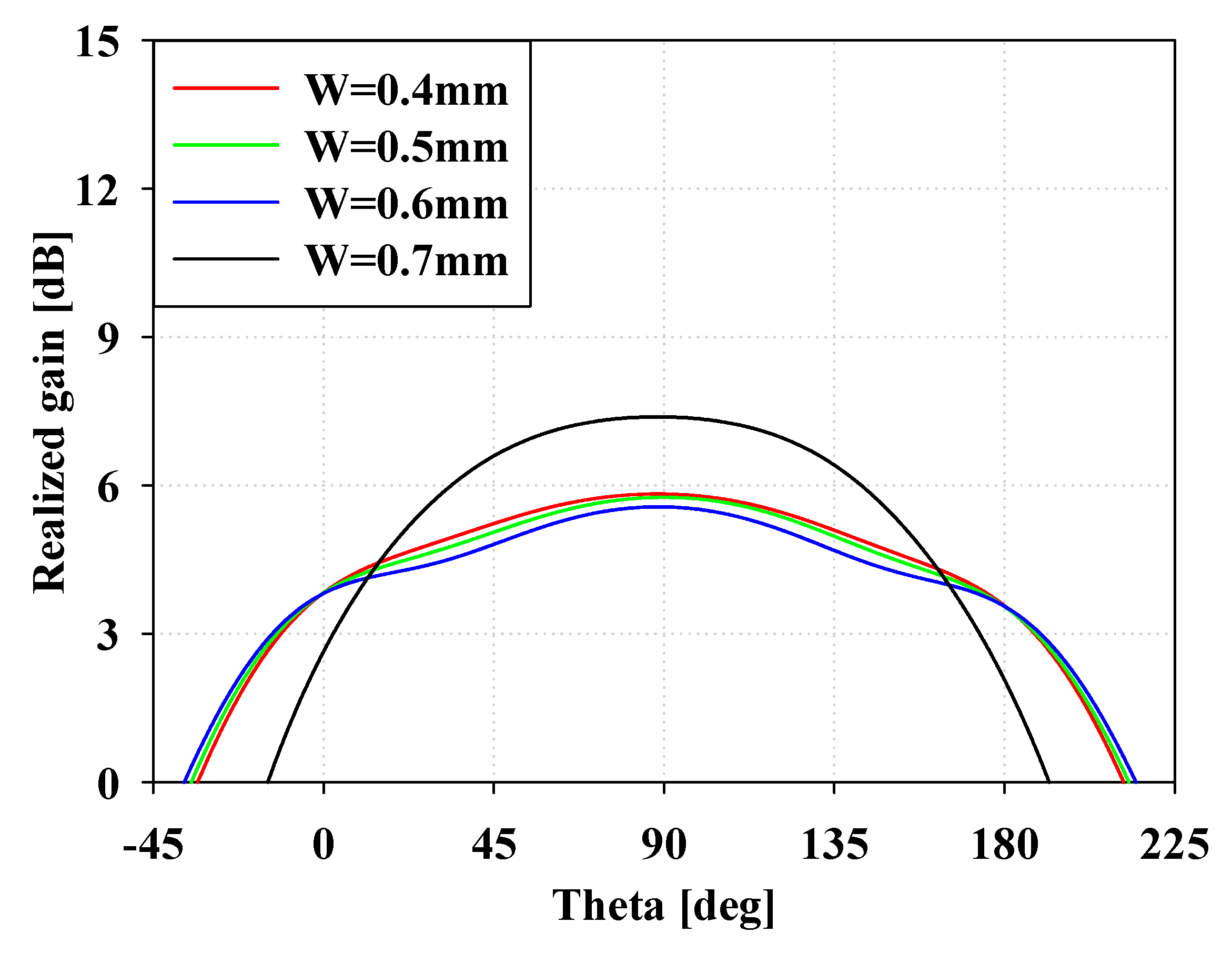
16,
17]. In addition, the width of the slot W is a key parameter for determining the performance of HPBW in the elevation plane.
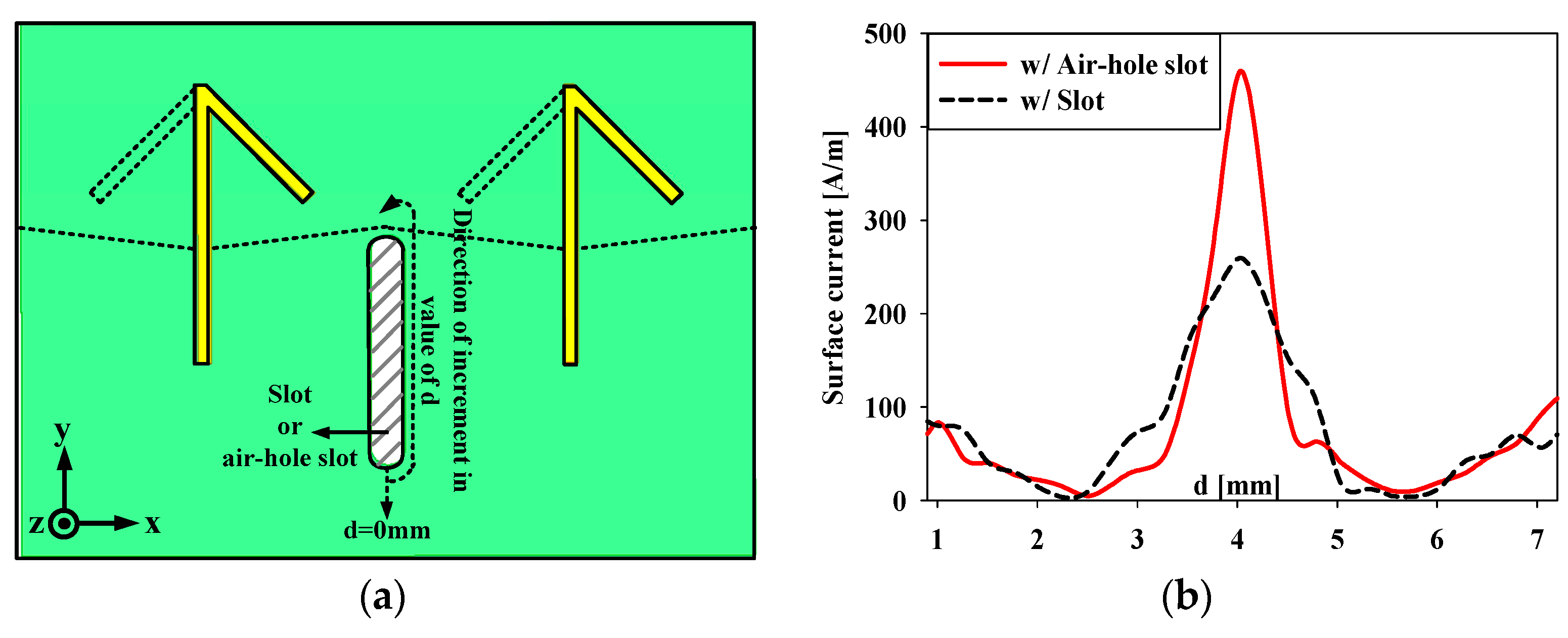
Figure 5 illustrates the parametric study of the width W. The optimized value of W is 0.5 mm since the peak gain starts to decrease at W = 0.6 mm and the HPBW becomes extremely narrow at W = 0.7 mm, which implies that the slot does not operate properly as a complementary dipole radiator.
To enhance the parasitic effect of the complementary dipole, an air-hole slot in the ground is introduced, as shown in
Figure 2a. The air-hole slot consists of a slot on the ground and an air-hole made by puncturing the substrate. The air-hole has an identical location and size of the slot, and is laid on the top of the slot. The effect of such an air-hole slot can be simply explained by the complementary theory in which all the materials should be completely complemented for thorough implementation [
18]. Such a theory can be further expanded upon using Maxwell’s equations as following [
19]:
Qualitatively, the total surface current around the slot is increased since the focusing of E field caused by the difference of relative permittivity between air hole and the substrate reinforces the second term on the right hand side of the equation of Amperes’ Law. This also increases the total magnetic field around the slot which is the left hand side of the Ampere’s Law. Since the H field is time-varying, the right-hand side of the Faraday’s Law increases and causally induces stronger total E field which is the left-hand side of the Faraday’s Law. Eventually, the induced stronger E field around the slot enables the radiation of the complementary dipole to be enhanced. Because of the pattern summing mechanism illustrated in
Figure 4b, the HPBW of the proposed array antenna in the elevation plane is improved. This is verified through observing the difference of the intensity of the surface current around the slot with and without the air hole.
Figure 6b shows the plot of the surface current (
y-axis) versus the distance around the slot (
x-axis) when it is applied alone and along with the air hole.
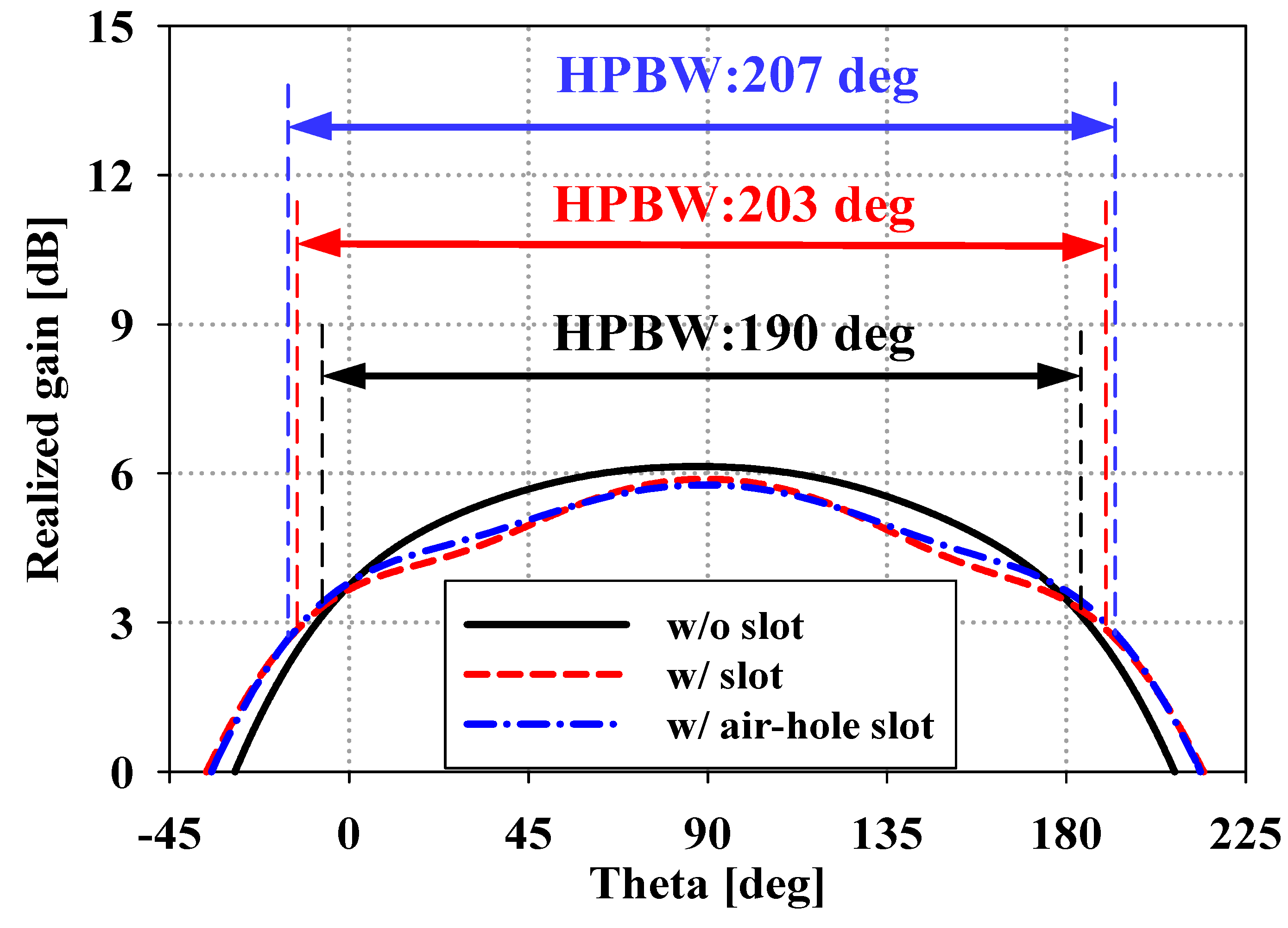
Figure 7 shows the radiation patterns of two-element arrays for three cases (i.e., without the slot, with the slot, and with the air-hole slot in the ground) in the YZ plane at 28 GHz. As we can see from the radiation pattern plot, the HPBW of the two-element array applied with the ground slot is increased from 190 degree to 203 degree compared with that without the ground slot. The HPBW is further increased to 207 degree in the YZ plane by introducing an air-hole slot instead of a ground slot.
3. Design of the Eight-Element Array on a Mobile Handset
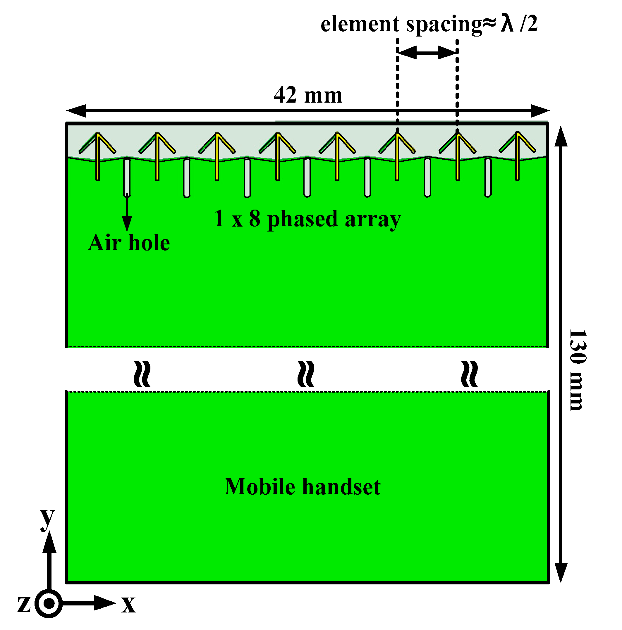
To verify the performance of a 5G phased array antenna on a typical mobile platform, the number of dipole elements is increased up to eight on a ground having the size of a typical mobile handset, as shown in
Figure 8. The 1 × 8 phased array antenna is located at the top side of the ground with the total dimensions of 130 mm × 42 mm × 0.127 mm. The detailed antenna parameters and the substrate material are identical to those of the two-element array case.
As shown in
Figure 9, the proposed antenna exhibits a −10 dB reflection coefficient bandwidth of 5.1 GHz while having the worst-case isolation level of 22 dB within that frequency bandwidth range.
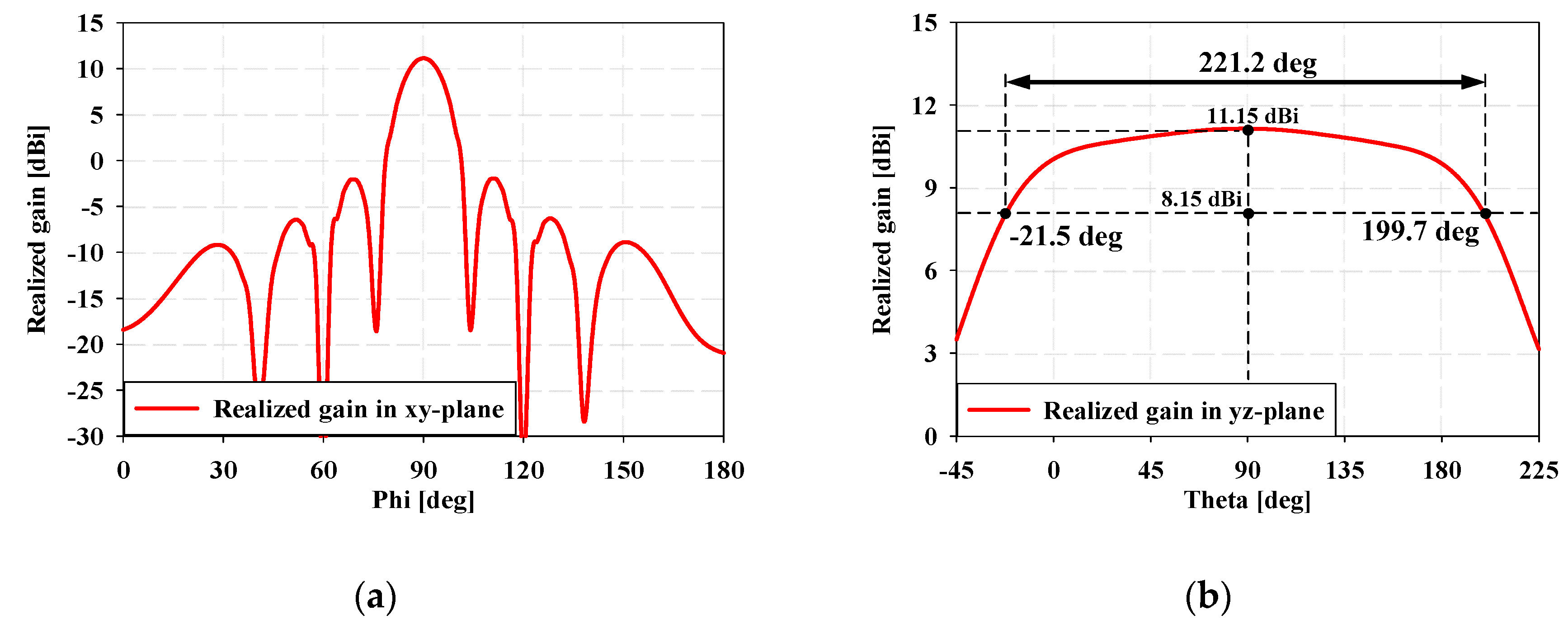
Figure 10a,b illustrate the radiation pattern of the proposed array antenna at 28 GHz with a 0 degree phase difference between ports in the azimuth (XY plane) and elevation (YZ plane) planes, respectively. As shown in the figure, the peak gain in the azimuth plane is 11.15 dBi toward +y direction with a side lobe level (SLL) of 13 dB. On the other hand, the proposed antenna exhibits a very wide HPBW of 221 degree in the elevation plane with a peak gain of 11.15 dBi. Regarding such results, the air holes superposed with the slots in the ground can provide a wide HPBW to the array antenna in the elevation plane regardless of the number of elements.
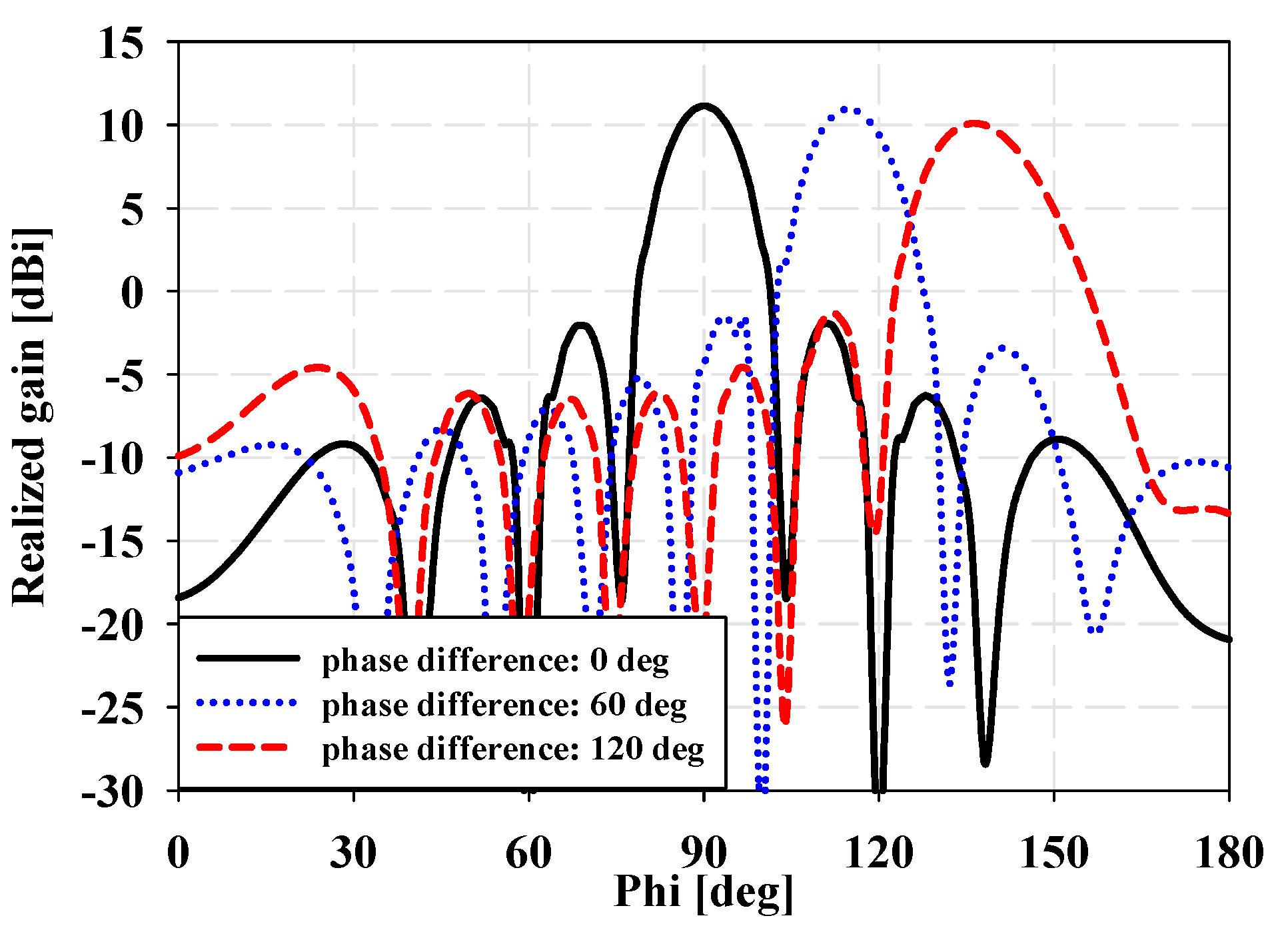
Figure 11 shows the beam-scanning performance of the proposed array antenna in the azimuth plane. As shown in the figure, the proposed antenna has a probable scan angle of ±45 degree (i.e., a total of 90 degree resulting from the symmetric structure) while maintaining the worst-case peak gain and SLL of 10 dBi and 12 dB, respectively.
In summary, the proposed antenna exhibits adequate performances of reflection coefficient bandwidth, isolation level, peak gain, scan angle, and SLL [
13] while having very wide HPBW, up to 221 degree in the elevation plane. Therefore, the proposed antenna can provide coverage of more than half of a hemisphere as a sub-array element, since it covers 90 degree in the azimuth plane with beam scanning and 221 degree HPBW in the elevation plane. If four proposed 1
8 phased array antennas are mounted on four corners of the mobile handset device, they can thoroughly cover the whole isotropic sphere without having a shaded area, as shown in
Figure 1. Such characteristics can be a very crucial advantage when developing an array antenna system for 5G mobile handset applications.
4. Experimental Results
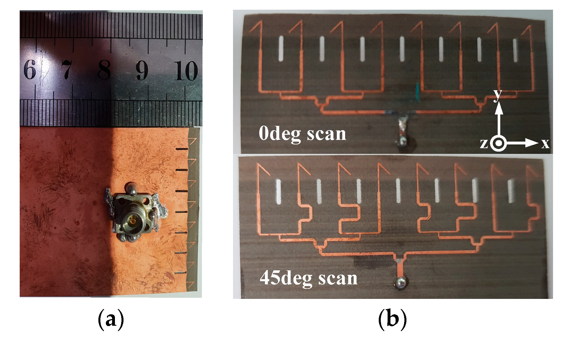
To verify the beam-steering performance, the proposed antenna was fabricated as a 1
8 mobile handset array antenna, as shown in
Figure 12a. Etching process was applied to print the metal patterns on both sides of the substrate while simple drilling was used to realize the air-hole slot. Two types of fixed microstrip feeding networks were implemented to represent the linear phase differences of 0 degree and 120 degree for a 0 and 45 degree scan, respectively, as shown in
Figure 12b. The substrate material and detailed antenna parameters for the proposed array antenna are identical to those of the two-element array design.
For measuring the reflection coefficient and the radiation pattern, Agilent N5230A vector network analyzer with Agilent/HP 85056D calibration kit and millimeter-wave anechoic chamber equipped with MTG operating software were used, respectively.
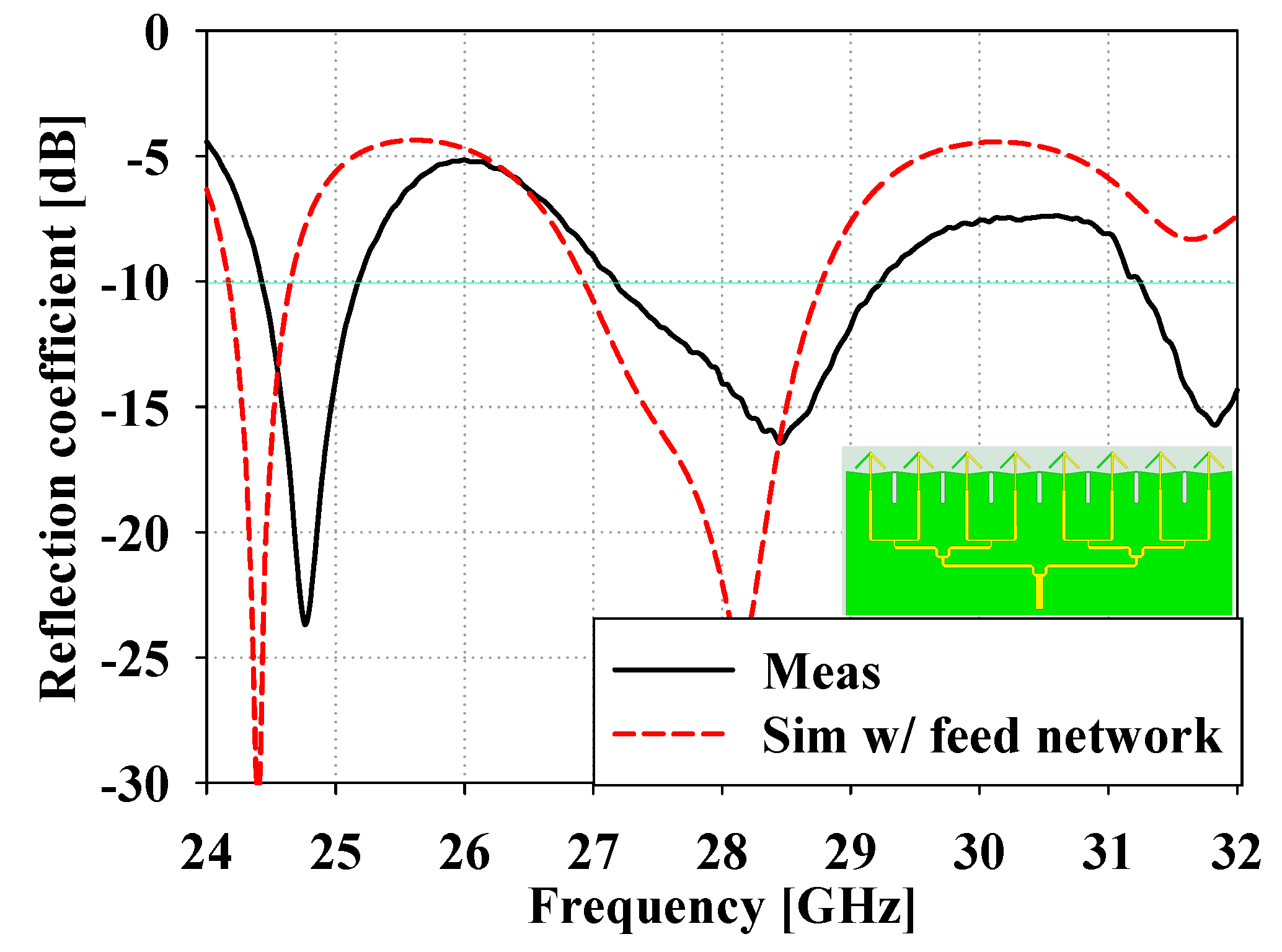
Figure 13 illustrates the measured reflection coefficients at the input port of the 1 8 array antenna with fixed microstrip feeding networks. The proposed array antenna has a 10-dB reflection coefficient bandwidth from 27.2 GHz to 29.2 GHz. As show in
Figure 13, the measured results agree reasonably well with the simulated ones implemented with the fixed feeding network. A slight discrepancy between the simulated and measured results can be explained as an outcome of errors from measuring and manufacturing.
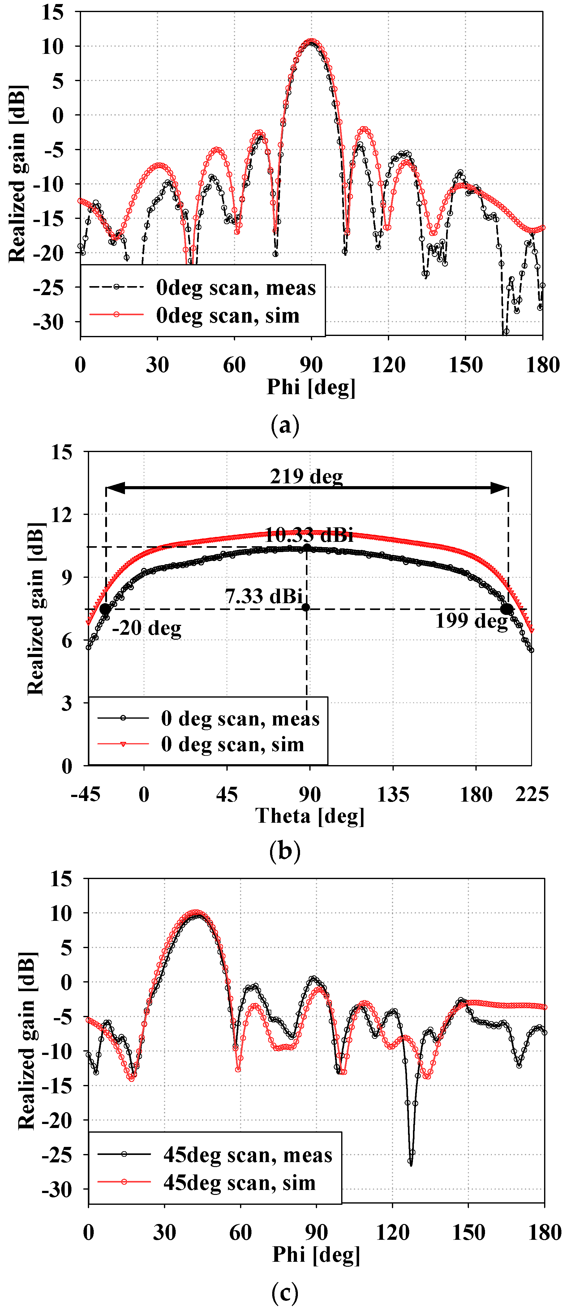
Figure 14 shows the measured radiation patterns of the proposed array antenna at 28 GHz along with the simulated results. Since the available anechoic chamber was technically specified to provide accurate results only for a rotational range from −120 to +120 degree relative to the boresight, plots in
Figure 14 are illustrated within that range. As shown in
Figure 14a,b, the measured peak gain of the array antenna with a 0-degree scan is 10.33 dBi in the XY plane with a HPBW of 219 degree in the YZ plane. As shown in
Figure 14c, the measured peak gain of the array antenna with a 45 degree scan is 9.64 dBi in the XY plane with an SLL of 10.1 dB. As shown in the figures, the measured radiation patterns reasonably agree well with the simulated results, except for a small discrepancy in the gain value of approximately 0.8 dB, which can be interpreted as an experimental error, including loss from the feeding connector. In summary, the fabricated antenna shows very wide HPBW in the elevation plane, while maintaining adequate performance in the other criteria, and agreeing reasonably well with the simulated results.
5. Conclusions
A 1 × 8 phased array antenna for 5G applications operating at 28 GHz with enhanced HPBW is proposed in this paper. The proposed design is proven to have sufficient impedance matching, sufficient peak gain, a low sidelobe level, suitable scan coverage, and very wide HPBW in the elevation plane. The HPBW improvement over 20 degree is achieved by introducing air-hole slots, as compared to that without air-hole slots. Such enhancement of the HPBW in the elevation plane can be explained by the qualitative causality of two Maxwell’s equations. Relatively good agreement between simulated and measured results can be explained by the simple structure of the proposed antenna since it has less factors for possible errors. Because of the very wide HPBW in the elevation plane along with reasonably good other radiation performances, the proposed array antenna can be a good candidate for the mm-wave 5G mobile handset applications. Future work will involve introduction of actual mobile handset model including metal chassis, circuit elements, and LCD panel. Since the performance of the antenna will be strongly affected by such inclusion, certain counter measures for minimizing the effect needs to be assessed. In addition, the effect of materials (dielectric or ferrite) that might be used to fill the air hole in actual situation, may also be taken into account.

