Article

Toolpath Strategies for 5DOF and 6DOF Extrusion-Based Additive Manufacturing

by
Mathias Laustsen Jensen
1,
Rasoul Mahshid
1,
Greta D’Angelo
2,
Jeppe U. Walther
1,
Malte K. Kiewning
1,
Jon Spangenberg
1,
Hans Nørgaard Hansen
1 and
David Bue Pedersen
1,*
1
Department of Mechanical Technology, The Technical University of Denmark, 2800 Kgs. Lyngby, Denmark
2
AMEXCI AB, 691 51 Karlskoga, Örebro County, Sweden
*
Author to whom correspondence should be addressed.
Appl. Sci. 2019, 9(19), 4168; https://doi.org/10.3390/app9194168
Submission received: 4 July 2019 / Revised: 10 September 2019 / Accepted: 30 September 2019 / Published: 4 October 2019
(This article belongs to the Section Mechanical Engineering)

Abstract

:
This paper introduces two new deposition-strategies for five degrees of freedom (5DOF) and 6DOF extrusion-based additive manufacturing (AM), called the tool path projection- and parent-child-approach, respectively. The tool path projection method can be automated, and allows for the generation of concentric shells layers, which remedy geometrical deviations (known as the stair-case effect) that are typically seen in 3DOF AM processes that potentially require secondary post treatment by machining or grinding of the final part. In the parent-child approach, the designer specifies the manufacturing direction for each distinct feature, thereby helping to remove the need for support material, as well as enabling new features to be dynamically added to the part.

1. Introduction

Extrusion-based additive manufacturing (AM) is in its current state primarily dominated by layered strategies in which a geometry is manufactured by consolidating thin layers of material [1,2] using three degrees of freedom (DOF). This is also true for higher DOF systems, such as 6DOF robot arms [3], i.e., systems that, despite more than a decade of research efforts into multiple DOF job generation methods and manufacturing setups, still operate using 3DOF strategies [4,5,6,7].
Some of the main issues of the 3DOF approach include anisotropic material properties, poor surface finish, especially on inclined surfaces, known as the stair-case effect [8,9,10,11,12], and the need for support for the overhangs. One approach to remedy these challenges is to utilize numerical models to improve the prints [13,14,15]. Another approach is to develop new AM deposition strategies that make it possible to expand the design space and to overcome the aforementioned issues. One such method is to enable out-of-plane surface contouring by increasing the DOF used at the job generation, to take full advantage of all axes of the system [16,17]. However, this comes at the cost of more complex job generation, as commonly recognized in the field of 5-axis CNC machining, where CAM preparation can be as time consuming as modelling the geometry to be manufactured [18,19]. For example, 5-axis job generation for AM requires a new approach, in which a STL file can no longer be sliced into simple layers from which the tool paths are generated. Given that 5-axis numerical control machining is a mature manufacturing technology [20,21], it would be naive to expect that a 5DOF job for an additive machine tool could be generated autonomously without similar complexity.
The two proposed manufacturing strategies of this study are intended to reduce this complexity by minimizing the number of operation decisions required during the job generation, rather than making the system fully automated. In this work, efforts are put into the application of 5DOF in material extrusion-based AM, such that double-curved surfaces can be profiled, eliminating the stair-case effect and producing a component with less single plane anisotropy. In addition, a second approach is made to illustrate a parent-child approach of a robot-arm, based on a 6DOF system, to reduce support structures during the build, and allow new features to be dynamically added to the part. The two manufacturing strategies are verified on two separate systems. The tool-path projection is experimentally tested on a 5DOF parallel kinematics machine setup [22], whereas the parent-child strategy is experimentally tested on a 6DOF robotic arm and a stationary nozzle [23].

2. Methods

2.1. The Tool-Path Projection Approach

The tool-path projection technique that is presented in this paper was inspired by the texturing of 3D bodies used in computer-generated imagery (CGI). Within the field of CGI, texture wrapping is the most common method by which 3D bodies are texturized [24] (Figure 1A). The approach follows a sequence in which the surface of the geometry is unwrapped, and in its flattened form, texturized, often manually by a sketch artist, after which the geometry is wrapped back to its 3-dimensional shape. This method can be adapted as a tool path generation method to 5DOF AM by offsetting the computer aided design (CAD) body inwards in increments of one until all concentric shells have been generated. This approach differs from the conventional by-layer deposition method, in that the manufactured object will exhibit less material anisotropy. Unwrapping each concentric layer to a two-dimensional sheet drastically simplifies the automated tool path generation to an extent where the same algorithms can be exploited that are presently use in by-layer tool path generation [25]. Furthermore, in this approach, the deposition tool is angled perpendicular to the surface of the build at any given position, thereby dramatically altering the definition of the surface of the manufactured component, and thus removing the stair case effect. To verify this approach, a simplified implementation of tool-path projections to a double curved surface is implemented in this work and experimentally tested.

2.2. The Parent-Child Approach

The parent-child approach is inspired by the feature-on-feature modelling approach used in parametric CAD environments. A component is created by a hierarchy of features superimposed onto a global coordinate system. Each feature has its own local coordinate system, from which the manufacturing strategy of the additively-manufactured object can be planned, enabling the exploitation of existing job generation techniques (Figure 1B). Past examples in the literature have illustrated how complex parts can be subdivided based on geometrical considerations [26]. The approach builds on generating features based on the typical 2.5D slicer software, and identifies features without support generation. The parent-child approach aims to provide the designers with tools to actively choose both how the parts are built and how to define the different features. This approach allows local features of the workpiece to be built in different directions by reorienting the workpiece accordingly, exploiting the 6DOF of the system.

3. Implementation

3.1. The Tool-Path Projection Approach

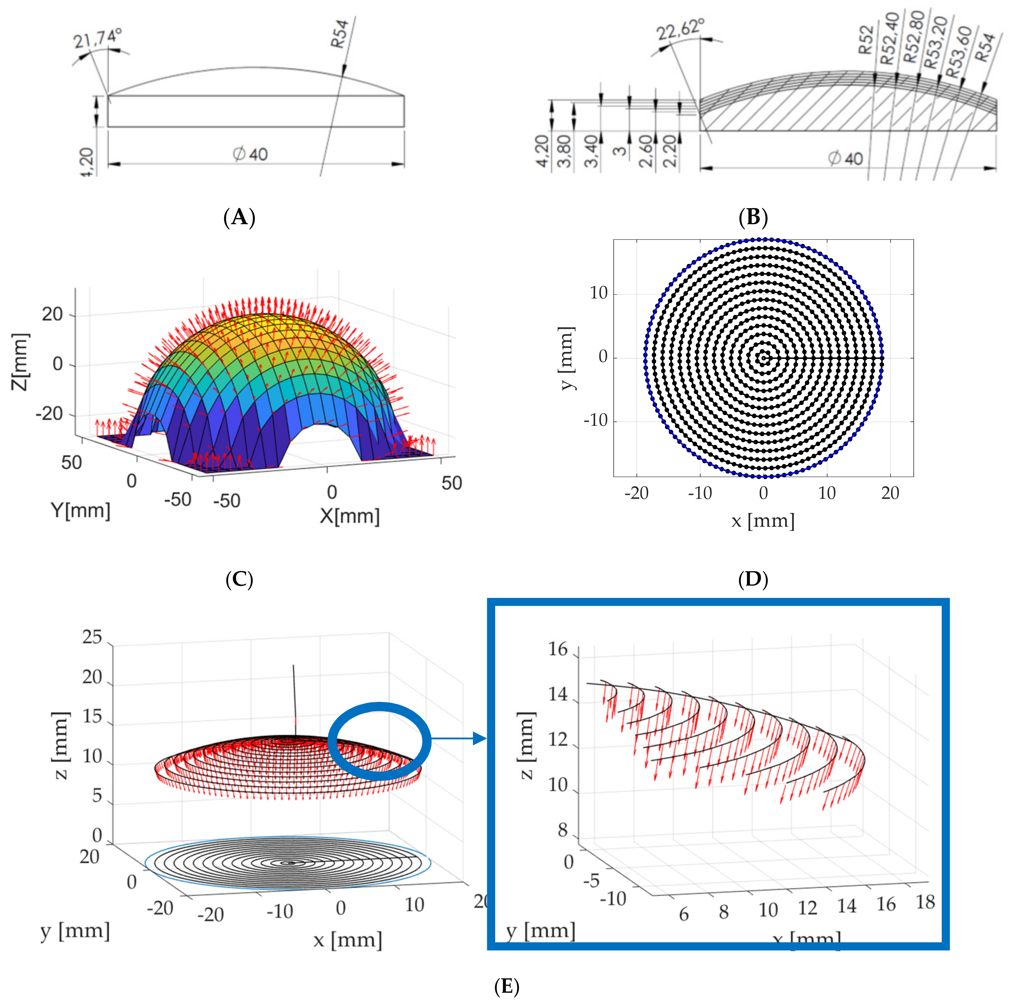
Two test objects are prepared to test the hypothesis that the 5DOF path projection-based setup can improve surface roughness properties, with one using a normal 3DOF pathing strategy and the other using the new 5DOF path projection-based pathing strategy (Figure 2A,B). The tool-path-projection job generator implemented in this study is a three-step manufacturing strategy containing a surface geometry generation, a creation of a g-code file, and a sequence that projects this g-code onto the generated surface geometry using an approximation function. The workflow consists of the initial parameterization of the specific layer, in which the different parameters are characterized to set up a discrete point cloud description of the desired 3D surface (Figure 2C), much like the typical STL description found in normal AM strategies. The height z for each x- and y-point on the discrete surface is calculated from the surface description of a hemisphere using the sphere radius. By this approach, the desired surface is discreetly described, as seen in (Figure 2C).
The next step is the creation of a 2D manufacturing strategy. For this, the path planning sequence is prepared in a plane and the strategy chosen is concentric circles, as this pattern easily coheres to the desired hemispheric shape; see Figure 2D. The planned 2D sequence is subsequently projected onto the 3D surface, as seen in Figure 2E. For each (x, y) coordinate on the 2D manufacturing strategy, the z-value and normal vector of the corresponding coordinate on the 3D geometry is calculated using bilinear interpolation. From these calculations, the surface-normal-values are inverted to cohere with the desired tooling orientation (Figure 2E); then, the normal vectors are converted to tilt orientations. This process is repeated for each layer of the part and the process-plan is exported into the g-code format for further implementation. By having these five coordinates for each command, it is possible to secure a conformal AM process using an arbitrary 5DOF AM machine.

3.2. The Parent-Child Approach

The parent-child method is implemented on an experimental setup with a stationary extruder and a 6 DOF robot manipulating a build plate mounted on the end effector. As mentioned in the previous section, each feature possesses its own coordinate system with respect to the global coordinate system. This will dictate the position of the robot end effector that will align the corresponding surface perpendicularly to the stationary nozzle and align with the local coordinate system of said features. In this context, the built features are assigned the role of the new receiving substrate for future features (Figure 1B). By employing this principle, all features are still being manufactured from planar layers following a 2.5D layout, but the increased degree of freedom allows the designer to have localized control over the layer orientation, and more complex geometries can be manufactured without the use of support material.
A Robot Operation System (ROS) is used for the software implementation of the parent-child method. ROS is a control environment that allows a wide variety of robot arms and kinematic systems to be controlled within a flexible, library-based framework [28]. This setup is used to prevent the need for reimplementing control of the individual joints in the articulator. The hardware utilizes a 6DOF articulated robot with a wrist infinite joint that is supported by ROS and the MoveIt motion planner framework, authored and maintained by Felix Messmer [29]. The articulated robot is set up in a virtual environment describing its relative position to a fixed extruder, as illustrated in (Figure 3A,B). This configuration enables the creation of AM pathways comprising of a series of waypoints that contain both a rotation and position in the global 3D Cartesian space.
The extrusion is handled over a serial connection to an extruder controller that operates the temperature control and drives the filament feed motor. The integration of this to ROS is illustrated in Figure 3A,B. The path-planning engine is restricted to prevent most self-collisions of the articulator arm, which is a necessity for the applied inverse kinematics model. Furthermore, the parts have been manufactured using procedural generated plans, but they can also be converted from g-code produced on various CAD/CAM software.

4. Results and Discussion

4.1. The Tool-Path Projection Approach

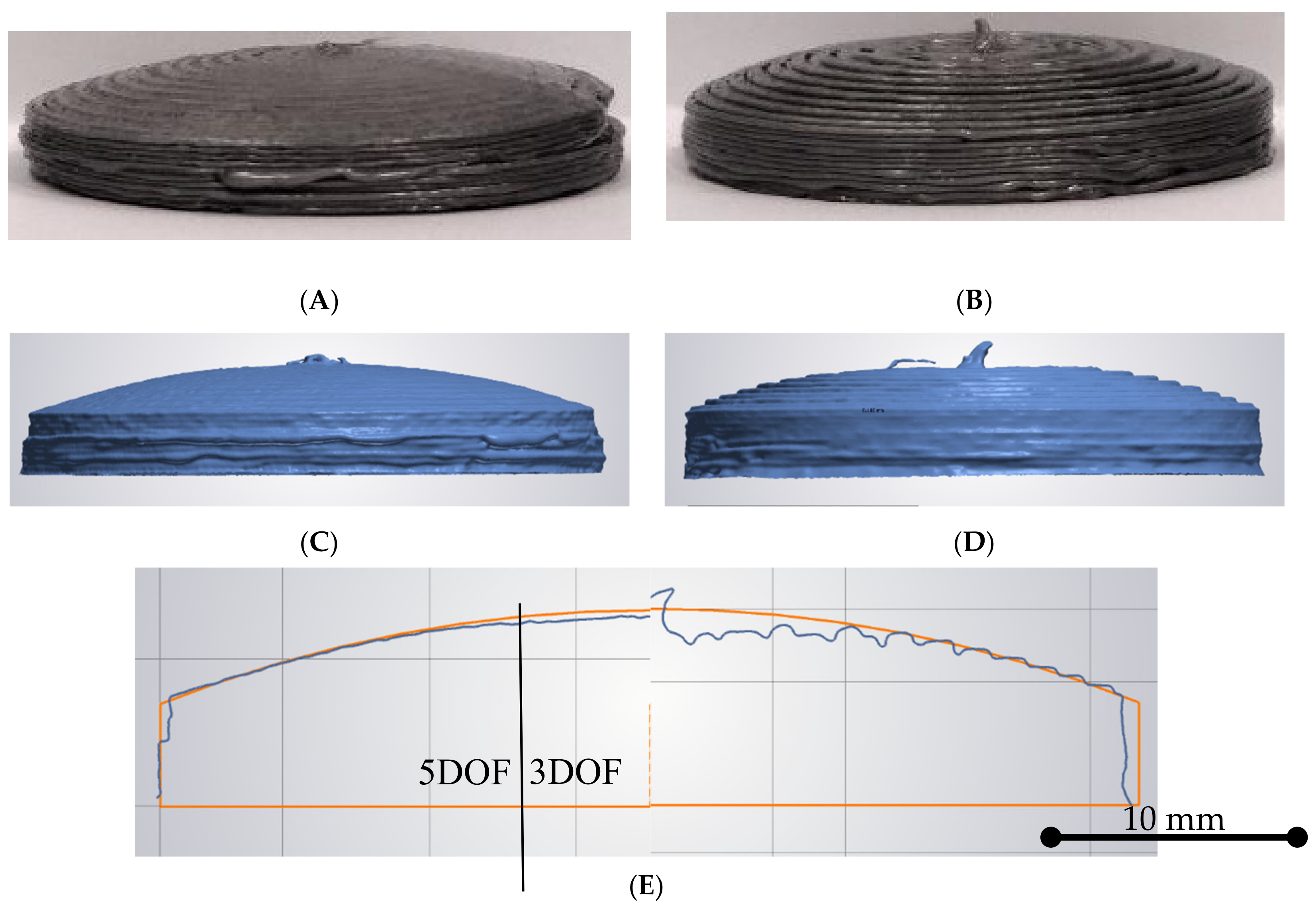
To test the tool-path projection approach against its ability to smoothen out the stair case effect, the initial tests were structured so that five hemispheric layers were applied onto a base structure made through conventional layered deposition. In this test, the results are compared to a conventional by-layer manufactured artifact; it was observed (Figure 4A,B) that the results improved the surface quality. Following this observation, an analysis of the artifacts using high-resolution 3D scanning further revealed the differences between the two approaches (Figure 4C,D). It was seen that the stair-chase effect was present in the conventional by-layer artifact, whereas this effect was not found in the 5DOF projection artifact. This shows that the approach can be used to improve the surface accuracy of the material extrusion-based surfaces without having to rely on time-consuming small layer-height approaches or post-processes to reach a high surface finish on the produced parts. Hence, it is indicated that the tool path projection approach can improve the surface quality of rounded surfaces without changing nozzle size or layer height, thereby removing one of the clear disadvantages of the AM surface quality of, notably, material-extrusion-based processes. The approach demonstrated can still be improved, e.g., the linear interpolation approximation used to find the surface normal of the process plan could benefit from higher order approximations. In addition, automatic algorithms should be integrated to enable the texture wrapping approach for any given geometry.

4.2. The Parent-Child Approach

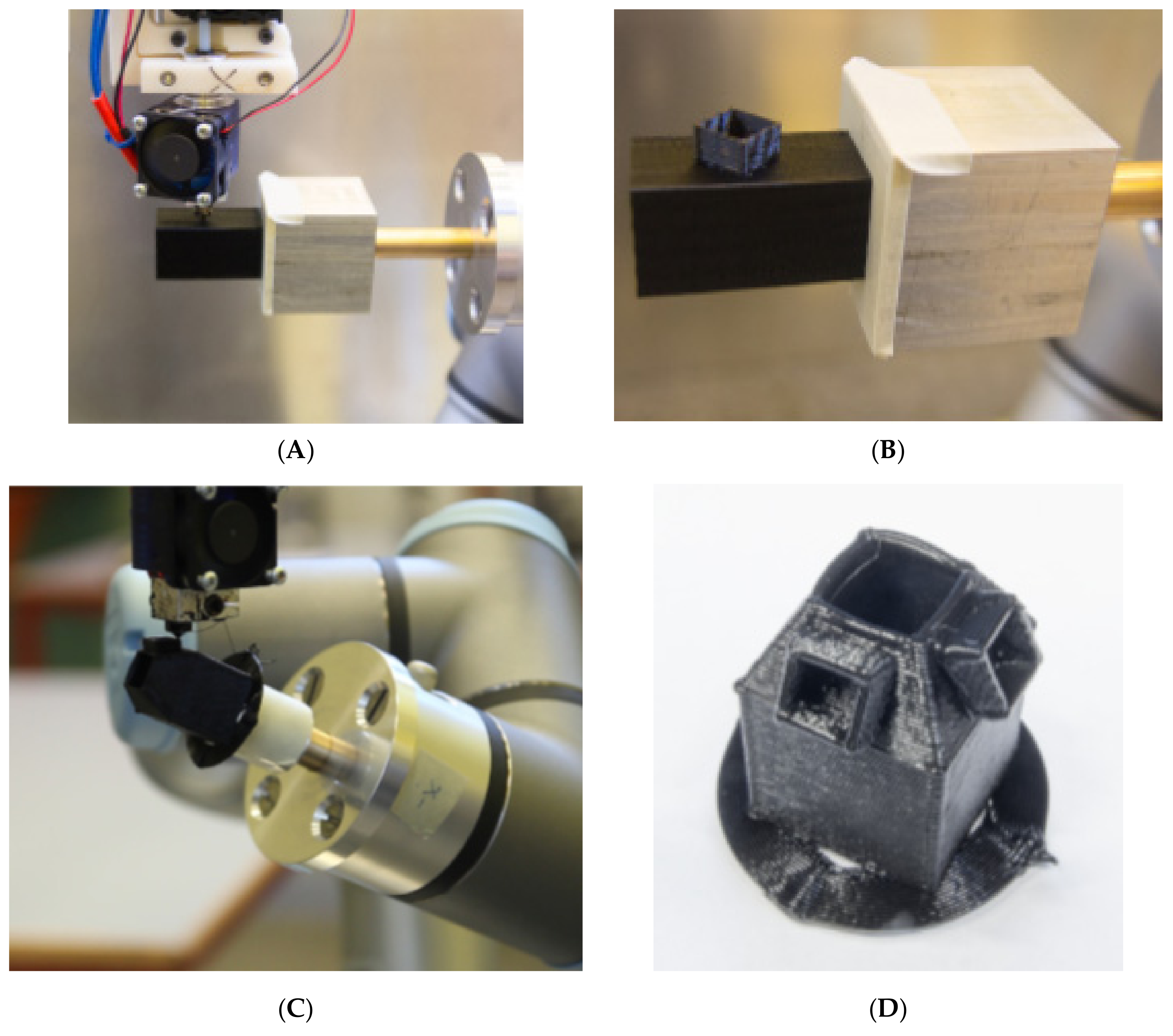
To investigate the applicability of the parent-child approach, two different geometries were prepared. The first is a hollow rectangular geometry with a small extruded square on the side (Figure 5A,B). This geometry is made to verify the coordinate change approach of the parent-child concept. The main rectangular geometry and the square feature on top of it are each characterized by their own coordinate system. Therefore, coordinate change must be made to create this product without the use of a support structure. Figure 5A,B presents a successful print of the test part, which would not have been possible with any other available system. From the success of the first geometry, a second, more complex geometry was produced, (Figure 5C,D). In this case, five different coordinate system changes were applied during the process. The first step was to align the moving build plate to the stationary nozzle in order to expand the build plate area. After that, the sequence to build the four additional features in different orientations was performed.
Due to the similarities with parametric 3D modelling, future manufacturing strategies could facilitate the designers’ process of creating new and advanced geometries that are less constrained by the available manufacturing processes. However, in order for this to happen, some issues need to be addressed; for example, the alignment of motion where an accurate definition of the tool control point is paramount. Since everything is related to the parent geometry, even small positional errors or misalignments in the parent geometry can have catastrophic results in the final process plan, leading to part collisions, etc. If the parent-child approach is then considered in a broader scenario, i.e., where deposition from multiple nozzles take place, the need for accurate positioning becomes increasingly important. This will require accurate and precise calibrating procedures and highly complex motion planning.

5. Conclusions

In this paper, two new AM strategies were presented and discussed. The first approach, a projection-based manufacturing strategy, demonstrates a 5DOF approach which is capable of improving the surface finish of rounded surfaces by removing the staircase effect of material extrusion-based processes. This approach was inspired by the texture treatment found in the gaming industry that enables convex and concave surfaces to be unfolded and flattened for the easy treatment of datasets. To demonstrate the concept, a projection path process was developed to illustrate some of the basic ideas behind the approach. In this investigation, the approach was demonstrated and verified against the conventional manufacturing strategy of AM parts. It was found that the process enabled new deposition strategies for out-of-plane depositions, which could potentially help the further advancement within, e.g., continuous fiber AM composite manufacturing.
The second approach, the parent-child, illustrates an alternative process for applying differently-oriented layers using multiple reference coordinate systems. This approach makes it possible to manufacture complex parts without support materials, using a 6DOF articulated robot as the build plate and a fixed extruder. The current proof of concepts were only tested with procedurally-generated construction plans, but future versions will require the automatic generation of motion plans based on CAD models. However, despite the requirements for the further implementation of this approach, the promising results show great potential for the use of this method in industrial application, especially for multiple-material deposition and automated manufacturing AM production.

Author Contributions

All others have contributed substantially to the research work and manuscript preparation.

Funding

This research was supported by the Innovation Fund Denmark (Contract No. 5139-00021B). J.S. was also partially supported by the Danish Council for Independent Research (DFF) Technology and Production Science (FTP) (Contract No. 7017-00128).

Conflicts of Interest

The authors declare no conflict of interest.

References

  1. ASTM International. Standard Terminology for Additive Manufacturing–General Principles–Terminology; ASTM International: West Conshohocken, PA, USA, 2015. [Google Scholar]
  2. Serdeczny, M.P.; Comminal, R.; Pedersen, D.B.; Spangenberg, J. Experimental validation of a numerical model for the strand shape in material extrusion additive manufacturing. Addit. Manuf. 2018, 24, 145–153. [Google Scholar] [CrossRef]
  3. Pires, J.N.; Azar, A.S. Advances in Robotics for Additive/Hybrid Manufacturing: Robot Control, Speech Interface and Path Planning. Ind. Robot Int. J. 2018, 45, 311–327. [Google Scholar] [CrossRef]
  4. Singh, P.; Dutta, D. Multi-Direction Slicing for Layered Manufacturing. J. Comput. Inf. Sci. Eng. 2001, 1, 129–142. [Google Scholar] [CrossRef]
  5. Ding, Y.; Dwivedi, R.; Kovacevic, R. Process Planning for 8-Axis Robotized Laser-Based Direct Metal Deposition System: A Case on Building Revolved Part. Robot. Comput. Integr. Manuf. 2017, 44, 67–76. [Google Scholar] [CrossRef]
  6. Song, X.; Pan, Y.; Chen, Y. Development of a Low-Cost Parallel Kinematic Machine for Multidirectional Additive Manufacturing. J. Manuf. Sci. Eng. 2015, 137, 021005. [Google Scholar] [CrossRef]
  7. Pan, Y.; Zhou, C.; Chen, Y.; Partanen, J. Multitool and Multi-Axis Computer Numerically Controlled Accumulation for Fabricating Conformal Features on Curved Surfaces. J. Manuf. Sci. Eng. 2014, 136, 031007. [Google Scholar] [CrossRef] [Green Version]
  8. Alexander, P.; Allen, S.; Dutta, D. Part Orientation and Build Cost Determination in Layered Manufacturing. Comput. Aided Des. 1998, 30, 343–356. [Google Scholar] [CrossRef]
  9. Bagsik, A.; Schöppner, V.; Klemp, E. FDM Part Quality Manufactured with Ultem*9085. In Proceedings of the 14th International Scientific Conference on Polymeric Materials, Halle, Germany, 15–17 September 2010. [Google Scholar]
  10. Quan, Z.; Wu, A.; Keefe, M.; Qin, X.; Yu, J.; Suhr, J.; Chou, T.W. Additive Manufacturing of Multi-Directional Preforms for Composites: Opportunities and Challenges. Mater. Today 2015, 18, 503–512. [Google Scholar] [CrossRef]
  11. Bourell, D.; Kruth, J.P.; Leu, M.; Levy, G.; Rosen, D.; Beese, A.M.; Clare, A. Materials for Additive Manufacturing. CIRP Annals 2017, 66, 659–681. [Google Scholar] [CrossRef]
  12. Comminal, R.; Serdeczny, M.P.; Pedersen, D.B.; Spangenberg, J. Numerical Modeling of the Material Deposition and Contouring Precision in Fused Deposition Modeling. In Proceedings of the 29th Annual International Solid Freeform Fabrication Symposium, Austin, TX, USA, 13–15 August 2018. [Google Scholar]
  13. Comminal, R.; Serdeczny, M.P.; Pedersen, D.B.; Spangenberg, J. Numerical modeling of the strand deposition flow in extrusion-based additive manufacturing. Addit. Manuf. 2018, 20, 68–76. [Google Scholar] [CrossRef] [Green Version]
  14. Comminal, R.; Serdeczny, M.P.; Pedersen, D.B.; Spangenberg, J. Motion planning and numerical simulation of material deposition at corners in extrusion additive manufacturing. Addit. Manuf. 2019, 29, 100753. [Google Scholar] [CrossRef]
  15. Serdeczny, M.P.; Comminal, R.; Pedersen, D.B.; Spangenberg, J. Numerical simulations of the mesostructure formation in material extrusion additive manufacturing. Addit. Manuf. 2019, 28, 419–429. [Google Scholar] [CrossRef]
  16. Marsan, A. A Review of Process Planning Techniques in Layered Manufacturing Prashant Kulkarni. Rapid Prototyp. J. 2008, 6, 18–35. [Google Scholar] [CrossRef]
  17. Ding, D.; Pan, Z.; Cuiuri, D.; Li, H. A Multi-Bead Overlapping Model for Robotic Wire and Arc Additive Manufacturing (WAAM). Robot. Comput. Integr. Manuf. 2015, 31, 101–110. [Google Scholar] [CrossRef]
  18. Rea Minango, S.N.; Ferreira, J.C.E. Combining the STEP-NC Standard and Forward and Inverse Kinematics Methods for Generating Manufacturing Tool Paths for Serial and Hybrid Robots. Int. J. Comput. Integr. Manuf. 2017, 30, 1203–1223. [Google Scholar] [CrossRef]
  19. Zhu, W.; Lee, Y.S. Five-Axis Pencil-Cut Planning and Virtual Prototyping with 5-DOF Haptic Interface. Comput. Aided Des. 2004, 36, 1295–1307. [Google Scholar] [CrossRef]
  20. Bohez, E.L.J. Five-Axis Milling Machine Tool Kinematic Chain Design and Analysis. Int. J. Mach. Tools Manuf. 2002, 42, 505–520. [Google Scholar] [CrossRef]
  21. Sarma, E.S. Automatic 5-Axis NC Toolpath Generation; Massachusetts Institute of Technology: Cambridge, MA, USA, 2001. [Google Scholar]
  22. Jensen, M.L. New Production Paradigms for Wind Turbines. Ph.D. Thesis, Technical University of Denmark, Lyngby, Denmark, 2019. [Google Scholar]
  23. D’Angelo, G. A Platform for Multi Material Additive Manufacturing, Modular Tooling and Process Verification. Ph.D. Thesis, Technical University of Denmark, Lyngby, Denmark, 2016. [Google Scholar]
  24. Catmull, E. A Subdivision Algorithm for Computer Display of Curved Surfaces. Ph.D. Thesis, University of Utah, Salt Lake City, UT, USA, December 1974. [Google Scholar]
  25. CuraEngine, 2019. CuraEngine is a Powerful, Fast and Robust Engine for Processing 3D Models into 3D Printing Instruction. Available online: https://github.com/Ultimaker/CuraEngine (accessed on 4 October 2019).
  26. Lee, K.; Jee, H. Slicing Algorithms for Multi-Axis 3-D Metal Printing of Overhangs. J. Mech. Sci. Technol. 2015, 29, 5139–5144. [Google Scholar] [CrossRef]
  27. Jensen, M.L.; Kiewning, M.K.; Spangenberg, J.; Andersen, S.B.; Pedersen, D.B.; Hansen, H.N. A 5D Dof Parralel Kinematic Controller for Big Area Additive Manufacturing. In Joint Special Interest Group Meeting between Euspen and ASPE Dimensional Accuracy and Surface Finish in Additive Manufacturing 2018; American Society for Precision Engineering: Berkeley, CA, USA, 2018. [Google Scholar]
  28. ROS.Org. n.d. ROS.Org|Powering the World’s Robots. Available online: http://www.ros.org/ (accessed on 3 December 2018).
  29. MoveIt. n.d. Moving Robots into the Future. Available online: http://moveit.ros.org/ (accessed on 7 November 2018).
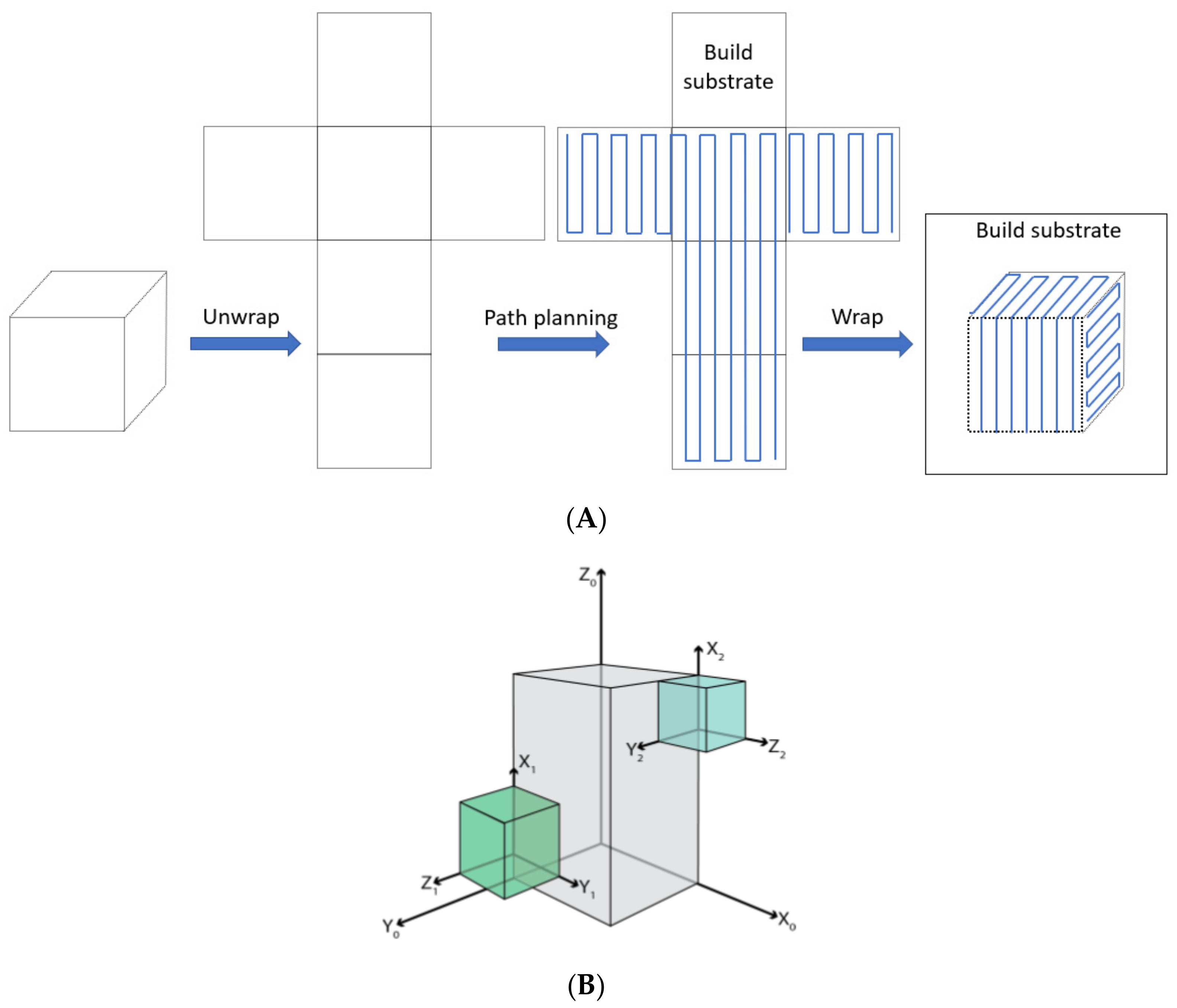
Figure 1. Principle sketches of the two concepts presented in this paper: (A) illustrates the general concept of texture wrapping [24] as a path planning tool for multi DOF AM. (B) Illustrates a sample geometry that has been divided into three parts, each belonging to a different coordinate system, in order to print without support structure [23].
Applsci 09 04168 g001
Figure 2. Pictures of the projection process [27]: (A) The reference geometry used for the 3DOF comparison approach. (B) Test geometry for the 5DOF approach of this study. (C) The surface description of the used hemisphere to describe the desired 3D shape. On this surface, a discrete pattern is used to describe the surface with corresponding normal vectors. (D) The concentric build approach used in this work. (E) An illustration of the projected patterns onto the desired shape (black) with its normal vectors (red).
Applsci 09 04168 g002
Figure 3. Sketches and illustration of the parent-child AM approach [23]. (A) ROS environment showing the articulated robot and its position relative to the extruder. (B) Sketch illustrating the overall framework of the ROD/UR3/extruder controller.
Applsci 09 04168 g003
Figure 4. Results of the PLA deposition [27]. (A) Results of the 5DOF AM approach. (B) Results of the 3DOF AM approach for comparison. (C) Microscopic results of the 5DOF approach. (D) Microscopic results of the 3DOF approach. (E) Sketch comparison of the results with scale.
Applsci 09 04168 g004
Figure 5. Results of the parent-child approach [23]. (A,B) are pictures of the initial trials. (C,D) present the second iteration of a more complex product that aims at illustrating the power of the approach with both substrate expansion and critical angles, which does not require any kind of support material.
Applsci 09 04168 g005