Abstract
This paper investigates the fault-tolerant tracking control problem of high-speed trains (HSTs) subject to unknown model parameters with unavailable uncertainties, unmeasurable additional disturbance, and unpredictable actuator faults constrained by actuator saturation. An adaptive passive fault-tolerant tracking control strategy based on variable-gain proportion-integral-derivative (PID)-type sliding mode surface is proposed to handle the problem. Unknown model parameters, gains of the PID-type sliding mode surface, and upper bounds of the lumped system uncertainty which includes additional disturbance, modeling uncertainties, and uncertainties resulting from actuator faults, are estimated online by adaptive technology. The input saturation (actuator output saturation) constraint is handled by introducing an auxiliary signal. The proposed controller can compensate for the effects of the lumped uncertainty and the actuator faults effectively. Moreover, the controller is model-independent, which means it requires no prior knowledge of model parameters and upper bounds of the lumped uncertainty, and does not depend upon fault detection and diagnosis module. The asymptotic stability of the closed-loop train system is demonstrated by Lyapunov theory. Good fault-tolerant tracking capacity, effective anti-actuator saturation ability, and strong robustness of the proposed controller are verified via numerical simulation.
1. Introduction
Along with the increase of departure density of high-speed trains (HSTs) and higher requirements for punctuality, security and reliability, how to get accurate position and velocity tracking to desired curves under different environments is becoming increasingly important. Consequently, considerable train tracking control schemes have been employed [1,2,3,4,5]. It is noted that some of the existing tracking control methods are model-dependent, which means that either entire or partial model parameters such as train mass, resistance coefficients, or additional disturbance of HSTs, are required as a priori. However, the model parameters and additional disturbance of HSTs are uncertain and variable due to many factors such as changes of passengers and loads, line conditions, weather, train speed, etc. [6,7]. Thus, it is difficult to get precise knowledge of a train model in practice. In addition, parametric uncertainties are neglected in the control schemes mentioned above. Ignoring parametric uncertainties would give rise to certain control deviation, which makes it difficult to maintain good control performance in practical train tracking operation. Therefore, the discussion mentioned above leads to a motivation to design a tracking control strategy for HSTs without the requirements of precise model parameters, whereas with strong robustness against additional disturbance and parametric uncertainties.
To solve the problems stated above, in [8], a model-independent position and velocity tracking control strategy based on robust adaptive nonsingular terminal sliding mode was proposed for HSTs with model parametric uncertainties and additional disturbance. The proposed controller achieves good tracking performance and strong robustness. Despite the efforts above, the inescapable occurrence of actuator faults during the long-term and long-distance train operation is not considered. Actuator faults may deteriorate train performance severely and even threaten the safety of passengers’ lives and property. However, due to the uncertainties of actuator faults in amplitudes and instants, it is challenging to compensate for the failures and maintain good tracking performance. Fault-tolerant control is a good solution to guarantee safe and reliable operation of HSTs subject to actuator faults. There are two kinds of fault-tolerant control approaches: active fault-tolerant control and passive fault-tolerant control. Performance of the former depends heavily on the accuracy and timelessness of fault detection and diagnosis module, while the latter does not require fault information feedback [9]. As a result, passive fault-tolerant control can compensate for fault effects much faster. Thus, many efforts on passive fault-tolerant tracking control for HSTs have been addressed [10,11,12,13,14]. In [10], a fault-tolerant controller using a so-called virtual-parameter-based backstepping adaptive control method was designed. It is fully parameter independent and can guarantee closed-loop tracking stability of the train system. In [11], in the face of actuator faults with unknown amplitudes and occurrence time, an adaptive fault-tolerant control scheme based on radial basis function (RBF) neural networks (NN) was adopted and asymptotical position and speed tracking was achieved. In [12], two novel adaptive fuzzy fault-tolerant control schemes with proportion-integral (PI)-based sliding mode were investigated to deal with the actuator failures of HSTs with uncertain parameters, unknown non-linear dynamics, and external disturbances. In [13], a neuroadaptive proportion-integral-derivative (PID)-like controller for HSTs was developed, which is independent of train model and insensitive to system uncertainties, additional disturbance, as well as actuator faults. In [14], a failure compensation controller was proposed for HSTs in the presence of actuator faults, time-varying system parameters, and disturbances. Despite the presence of actuator faults, the fault-tolerant control schemes mentioned above achieve good tracking performance.
However, it is worth noting that actuator output saturation, which means that the control input is subject to a certain restriction, has not been concerned in the literature mentioned above. In fact, actuator output saturation is also an extremely crucial factor in practical systems [15]. Controllers designed without considering actuator saturation would suffer from performance degradation or even instability in the presence of actuator saturation [16,17,18]. Obviously, actuator faults and actuator output saturation should be considered simultaneously to obtain satisfactory tracking performance for HSTs. A series of control strategies have been proposed to deal with actuator faults and actuator saturation simultaneously [19,20,21]. However, only a handful of literature is exclusively for HSTs [22]. In [22], a neural adaptive control scheme based on a novel sliding mode surface was investigated for HSTs subject to unknown basic resistance, additional disturbance, actuator faults and actuator saturation. In the paper, the additional disturbance was approximated by RBF NN, so that the control performance depends, to some extent, upon the number of neurons and the NN parameters including the width, the centers (Gaussian NN) and so on. However, there lacks a general guideline for the choices of these parameters. Besides, the adoption of RBF NN would increase computational burden of the fault-tolerant tracking controller for HSTs. Moreover, parametric uncertainties were not concerned, which would influence control effect in practical train operation. The uncertainties of parameters, additional disturbance, actuator faults, and actuator saturation have great impacts on the stability and control performance of the control system. Therefore, how to design a robust controller for HSTs considering these factors simultaneously has become an urgent need.
Motivated by the above analysis and inspired especially by the work of Lin et al. [22], an adaptive passive fault-tolerant tracking control strategy based on a variable-gain PID-type sliding mode surface is presented for HSTs in which parametric uncertainties, additional disturbance, unknown actuator faults, and actuator output saturation are taken into account simultaneously. The adopted variable-gain PID-type sliding mode surface is featured with variable gains and can offer fast transient response, low steady-state error, and strong robustness [23]. An adaptive adjustment technique is employed to estimate the nominal model parameters, upper bounds of the lumped uncertainty, and gains of the PID-type sliding mode surface, respectively. An auxiliary signal is introduced to deal with actuator saturation. The proposed strategy is fully model-independent and does not require the information of actuator faults. As a result, simple structure and inexpensive computation are achieved, which is exactly what is expected in practical application. Based on Lyapunov theory and simulation results, it is analyzed and demonstrated that the proposed controller can track the desired position and velocity trajectories accurately, and has strong robustness to the lumped uncertainty and the actuator faults.
The rest of this paper is organized as follows. Section 2 provides the train dynamical model and formulates the problem statement. Section 3 derives the adaptive passive fault-tolerant tracking control strategy for HSTs based on variable-gain PID-type sliding mode surface. Section 4 presents the simulation results and verifies the effectiveness of the control strategy. Finally, some concluding remarks are given in Section 5.
2. Train Dynamical Model and Problem Statement
2.1. Description of Train Dynamical Model without Actuator Faults and Actuator Saturation
The single-point-mass model, which treats the train as a single particle, can describe the complete characteristics of the train, simplify the train modeling, and achieve good real-time performance, so it has been widely applied in the tracking control of HSTs [2,4,8,11,16,24,25,26]. Considering train dynamics in the longitudinal direction, the force diagram of a single-point-mass model of HSTs is depicted in Figure 1.
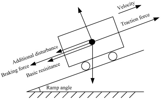
Figure 1.
Force diagram of longitudinal train dynamical model.
By Newton’s second law, the single-point-mass train dynamical model can be described as follows [22]:
where is the train total mass; and represent the position and the velocity, respectively; denotes the traction force (traction phase) or braking force (braking phase); means the additional disturbance from rail conditions, which is mainly composed of ramp resistance, tunnel resistance, curve resistance and other resistances. In practice, is unknown and varies with the corresponding environment. models the basic resistance, which is usually expressed by the Davis equation:
where , , are coefficients of the Davis equation.
Assumption 1.
The unknown and time-varying additional disturbancesatisfies, whereis a positive but unknown constant.
2.2. Description of Train Dynamical Model with Actuator Faults and Actuator Saturation
2.2.1. Actuator Faults
When the train is running on the line, due to the frequent execution of tasks, unanticipated actuator faults such as faults caused by overheating or turn-to-turn short circuits of motor, faults from overcurrent in the traction converter, faults from wear of mechanical drivers and so on, are inescapable. These failures can be classified into the following categories: lock-in-place fault, hard-over fault, float type fault, loss of actuator effectiveness, and so on [27], among which loss of actuator effectiveness is more severe and has higher probability of occurrence than other component faults [28]. Hence, loss of actuator effectiveness is considered in this paper.
For single-point-mass train dynamical model, the loss of actuator effectiveness faults, which means that the actuator partially loses its actuating power, can be considered as a whole [22]. Therefore, the real output of actuator subject to loss of actuator effectiveness faults can be described as follows:
where is the actual actuator output and represents output of the controller without actuator faults. stands for actuator’s effectiveness and satisfies . indicates the actuator totally failed; indicates the actuator is healthy and indicates the actuator occurs partial loss of effectiveness fault.
2.2.2. Actuator Saturation
From a practical perspective, control input is bound to be constrained by actuator output ability caused by various factors, such as maximum output of working motors. Thus, we introduce a saturation function to show the effect of actuator saturation, which has the following form:
where and represent the upper and lower bounds of , respectively. Define , where can be expressed as follows:
2.2.3. Description of Train Dynamical Model with Actuator Faults and Actuator Saturation
Considering loss of actuator effectiveness faults and actuator saturation simultaneously, the actual actuator output can be described as Figure 2.
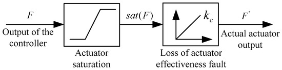
Figure 2.
Description of the actual actuator output.
As can be seen from Figure 2, the actual actuator output, i.e., the control force of HSTs, can be written as
For convenience of analysis, we define . Therefore Equation (7) can be rewritten as
Assumption 2.
In this paper, it is assumed thatis satisfied, whereis unknown.
Remark 1.
in Assumption 2 indicates that even if the actuator fails, it still can provide necessary traction force or braking force to drive the train tracking the desired trajectories. If the actuator fails seriously and the traction force or braking force produced is not enough to achieve the train tracking task, other measures must be taken. Thus, Assumption 2 is reasonable.
Considering loss of actuator effectiveness faults and actuator saturation, and combining Equation (8), Equation (2) can be transformed into
Note that the parameters , , , in Equation (9) are unknown and vary in a certain range due to many factors such as changes of passengers and loads, line conditions, weather, train speed, etc. Thus, it is necessary to add parametric uncertainties to train model dynamics. Taking parametric uncertainties into consideration, Equation (9) can be modified as:
where , , , represent the nominal values and , , , are the modeling uncertainties of , , , .
According to Equation (10), the following expression can be obtained:
where , , represents the lumped uncertainty which has the following expression:
2.3. Problem Statement
In this paper, the position and velocity tracking control problem of HSTs described as Equations (1) and (11) is investigated. The train is subject to loss of actuator effectiveness faults with unexpected amplitudes and occurrence time. Moreover, the parameters of the train dynamic model are unknown and uncertain, the additional resistance is unmeasurable, and the actuator output is constrained by actuator saturation.
The objective of this paper is to design a model-independent passive fault-tolerant tracking control scheme, which based on adaptive technology and variable-gain PID-type sliding mode surface for HSTs mentioned above, so that the lumped uncertainty caused by loss of actuator effectiveness faults, parameter uncertainties and additional disturbance can be well compensated, and the actuator saturation can be effectively handled. Meanwhile, the system is stable, and the position and the velocity of HSTs track the desired position trajectory and the velocity trajectory asymptotically.
3. Controller Design and Stability Analysis
An adaptive passive fault-tolerant tracking controller is designed in this section for HSTs subject to uncertain parameters, unmeasurable additional disturbance, unknown actuator faults and actuator saturation simultaneously, so that good tracking performance and excellent robustness can be ensured. In view of the strong robustness to parametric uncertainties and disturbances, as well as the requirement to relax the system knowledge, variable-gain PID-type sliding mode surface is introduced and adaptive technology is adopted in the controller design.
To facilitate controller design, we define position tracking error, velocity tracking error and acceleration tracking error as , and , where , and are the desired position, velocity and acceleration, respectively.
Assumption 3.
It is assumed that the actual state variables,andare measurable. In addition, the desired trajectories,, andare smooth, bounded, and computable.
Traditional proportion-derivative (PD)-type sliding mode surface has slow response speed, while fixed-gain PID-type sliding mode surface may intensify the vibration of the control signal and induce the excitation of high-frequency unmodeled dynamics of system [29]. Thus, variable-gain PID-type sliding mode surface, which can offer fast transient response and small steady-state error, is adopted in this paper. According to the position and velocity tracking errors, PID-type sliding surface with variable gains is selected as follow [22,23]:
where and are two variable gains updated by adaptive laws to be designed later.
Then the time derivative of Equation (13) is:
To deal with the actuator saturation, an auxiliary signal is introduced as follows:
where is a positive constant chosen by the designers.
Define . Then,
Substituting Equations (11), (14), and (15) into Equation (16), yields to
Theorem 1.
For the train dynamics described in Equations (1) and (11) subject to uncertain parameters, unmeasurable additional disturbance, unknown loss of actuator effectiveness faults and actuator saturation simultaneously, suppose that Assumptions 1–3 are satisfied. If the sliding mode surface is selected as Equation (13) and the control law is designed as Equation (18), then all the signals of the closed-loop train system are bounded and asymptotically stable position and velocity tracking to the desired trajectories can be guaranteed.
whereandare the estimation ofand;andare positive constants satisfiedand, respectively;is a design parameter chosen by the designers;andare the estimation ofandwith the definition ofand, respectively. The parameter adaptive laws are selected as follows:
whereandare two positive definite matrices;;.
The gains of the selected sliding mode surface are estimated by
where and are two positive design parameters.
The block diagram of the proposed controller is depicted in Figure 3.
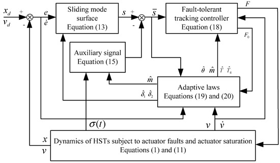
Figure 3.
Block diagram of the proposed controller.
Proof of Theorem 1.
To facilitate the proof of system stability, the estimation error terms are defined as follows: ; ; ; . □
Consider a candidate Lyapunov function given by
The first-order derivative is
Integrating Equations (17), (18a) and Equations (20), (22) can be computed as:
where , , , and are expressed as follows:
According to Equations (18b), (19a), and (19b), it can be obtained that
In practical train operation, the velocity is bounded by the limit speed from the automatic train protection (ATP) system [30]; the acceleration is constrained to make passengers comfortable; , , , and are also bounded. In addition, the discrepancy between actual actuator output and saturation limit (i.e., ) is bounded owing to the boundedness of the actual actuator output. Therefore, combined with Assumption 1 and Assumption 2, the lumped uncertainty satisfies:
where , . are unknown and positive.
Applying Equations (18c), (19c), and (29), yields to
From Equations (18d) and (19d), one has
For , it satisfies
Substituting Equations (28), (30), (31) and Equation (32) into (23), we can get
Since , , it is obvious that . Consequently, is a nonincreasing function and satisfies . Then, from Equation (21) it can be easily obtained that , , , , . Hence, based on Equations (15), (16), (17), and (33), it can be deduced that , , , and , which can ensure the boundedness of . Therefore, is a uniformly continuous function. By virtue of Barbalat’s lemma [31], it can be concluded that and as , which implies that , and as . Furthermore, it is easy to know that the closed-loop train tracking control system can guarantee asymptotic stability. Thus, the control objective is achieved, and the proof is completed.
Remark 2.
In the proposed controller,andare two compensation terms. Combined with the adaptive laws, Equations (19c) and (19d), they are used to compensate for the lumped uncertainty and the uncertainty caused by unknown loss of actuator effectiveness faults. From Equations (30) and (31), it can be observed that lumped uncertain ty, uncertainties (,and) caused by loss of actuator effectiveness faults are all well compensated.
Remark 3.
It is noted that the proposed control algorithm is independent of the model parameters and the prior knowledge of the upper bounds of lumped uncertainty. In addition, it requires no information of the actuator faults, so it does not need any fault detection and diagnosis module. Moreover, although parameteris introduced, it is involved neither in the control law nor in the adaptive laws, and only used in the process of proof.
Remark 4.
Fault-tolerant tracking control strategy based on a variable-gain PID-type sliding mode surface was also adopted in [22]. However, the additional disturbance was estimated by RBF NN, which makes it more complex and more computational than the proposed controller in this paper. Moreover, it does not consider the uncertainties of model parameters, which would influence the control performance as applied in actual train operation.
4. Simulation
In order to check the fault-tolerant tracking control capability of the proposed controller, numerical simulation has been carried out. The main simulation parameters and parametric uncertainties of the train model are described as [24]: , , , , , , , , and where “rand” represents a random value between 0 and 1.
The additional disturbance is given as follows:
where , , represent the tunnel resistance, curve resistance and ramp resistance, respectively [32]. In the simulation, the tunnel length , the curve length , the centric angle of the curve , and the ramp angle . stands for other resistance with the given value of .
Remark 5.
It is noteworthy that force of train gravity can help or hinder train movement depending on whether the ramp angle is positive or negative. However, the projection of gravity on the direction parallel to the track, which is unknown to the proposed controller, has been included in the lumped uncertainty, so no matter whether the force of gravity hinders or helps train movement, it would be compensated by the compensation termin our algorithm. Therefore, no matter whether gravity hinders or helps train movement, the train model and proposed algorithm are applicable.
It should be noted that the train parameters, parametric uncertainties, and additional disturbance given above, the actuator’s effective coefficients used in the following simulation, are unknown and not required in the design of the controller.
To verify the effectiveness of the designed controller, we simulated a running process with several operation conditions, which contains two acceleration phases, four cruising phases, and two deceleration phases, as depicted in Figure 4. Parameters of the designed controller were selected as: , , , , , , , , , . Initial values involved in the controller were chosen as follows: , , , , , , . The upper and lower bounds of are and , respectively. To mitigate the chattering and make the control force smooth, when , in the controller is replaced by , where is a small positive constant with the value of in the simulation. Based on the above simulation parameters, several different simulations were performed as follows to demonstrate the performance of the proposed controller.
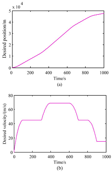
Figure 4.
Desired position and velocity: (a) desired position, (b) desired velocity.
4.1. Simulation Results for HSTs without Actuator Faults
To validate the feasibility of the proposed controller for HSTs under actuator fault-free condition, simulation for HSTs without actuator faults was carried out. The simulation results are shown in Figure 5. From Figure 5a,b, the proposed controller can ensure the position and velocity to track the desired trajectories accurately. Figure 5c shows that there is no obvious chattering in the actual actuator output and the actuator saturation limit is satisfied. Figure 5 demonstrates the feasibility and effectiveness of the proposed controller for HSTs despite in presence of model uncertainties, additional disturbance, and actuator saturation.
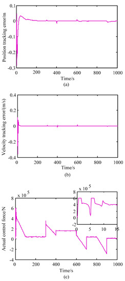
Figure 5.
Control performance for high-speed trains (HSTs) without actuator faults: (a) position tracking error, (b) velocity tracking error, (c) actual control force.
4.2. Simulation Results for HSTs with Different Magnitudes of Actuator Faults
To demonstrate the fault-tolerant tracking capacity of the proposed controller, simulations for HSTs with different magnitudes of loss of actuator effectiveness faults are performed. Different magnitudes of actuator faults can be simulated by changing the value of actuator effectiveness. Suppose that the actuator faults occur in 150 s and last until the end of the simulation. A 10%, 30%, and 50% loss of actuator effectiveness, i.e., , , and , are considered in the simulation. The simulation results are shown in Figure 6.
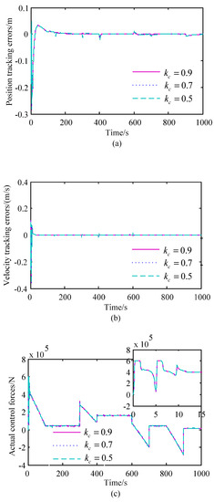
Figure 6.
Control performance for HSTs with different magnitudes of actuator faults: (a) position tracking errors, (b) velocity tracking errors, (c) actual control forces.
Along with the decrease of value, loss of actuator effectiveness faults becomes more and more serious and the impact of actuator faults on train tracking operation is growing. However, as can be seen from Figure 6, the position tracking error and the velocity tracking error do not increase significantly along with the severity of actuator faults and remain small all the time. It can also be seen that there is still no obvious chattering and the anti-actuator saturation is effective. Figure 6 illustrates that the proposed controller can accommodate loss of actuator effectiveness faults, handle actuator output saturation constraint, and has good fault-tolerant tracking capacity.
Remark 6.
As described in Assumption 2,is supposed to be bounded, thuswould be larger than a certain value, which means that the proposed controller in this paper is applicable to a certain limit of loss of actuator effectiveness faults. Through simulation experiments, when the loss of actuator effectiveness exceeds 65%, that is, when, the proposed controller in this paper will not work.
4.3. Simulation Results for HSTs without Anti-Actuator Saturation
In addition, to further verify the necessity of considering anti-actuator saturation in the design of a controller, simulation was carried out for the case without anti-actuator saturation. Without considering the anti-actuator saturation, and in the case of 30% loss of actuator effectiveness, i.e., , the control performance for HSTs with the actuator output limits and is shown in Figure 7. It can be seen that the tracking errors of the system increases substantially, and the system becomes unstable. Moreover, the chattering problem of the actuator’s actual output becomes very serious, which is not allowed in practical train operation. Figure 7 demonstrates the importance and necessity of considering anti-actuator saturation in train fault-tolerant tracking controllers.
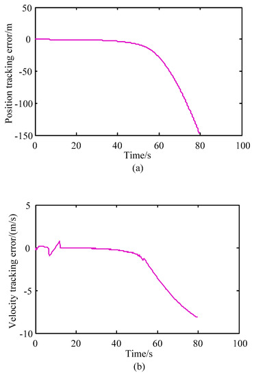
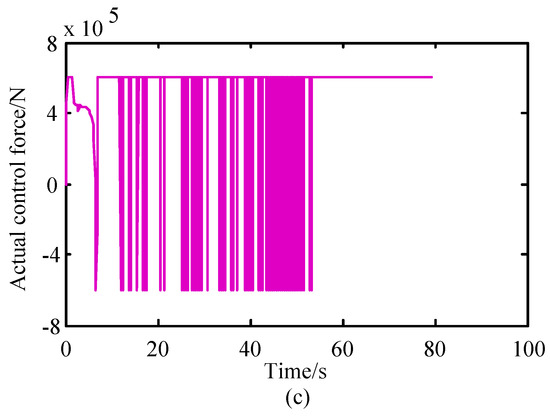
Figure 7.
Control performance for HSTs without anti-actuator saturation: (a) position tracking error, (b) velocity tracking error, (c) actual control force.
4.4. Simulation Results for HSTs with Larger Lumped Uncertainty
In order to prove the robustness of the system to the lumped uncertainty, two cases with lager lumped uncertainties are considered:
Case1: , and the parametric uncertainties are increased by 50%.
Case2: , and the parametric uncertainties are increased by 100%.
Given that . Using the same design parameters and initial values, the position tracking error and velocity tracking error are shown in Figure 8, which illustrates the proposed controller has strong robustness to the lumped uncertainty.

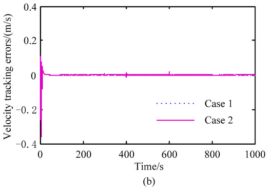
Figure 8.
Control performance for HSTs with larger lumped uncertainty: (a) position tracking error, (b) velocity tracking error.
5. Conclusions
In this paper, a dynamical model of HSTs subject to parametric uncertainties, actuator faults, and actuator saturation was built, and a passive fault-tolerant tracking control strategy independent of fault detection and diagnosis module was investigated. Considering the strong robustness of train system to the lumped uncertainty and actuator faults, as well as the requirement to relax system knowledge, a fault-tolerant tracking control algorithm based on adaptive technology and variable-gain PID-type sliding mode surface is presented. In the proposed controller, fault detection and diagnosis module, prior knowledge of the model parameters, and upper bounds of the lumped uncertainty are not required. To handle the actuator saturation, an auxiliary signal is introduced. Simulation results demonstrate the presented adaptive passive fault-tolerant control strategy has excellent tracking ability, good fault-tolerant capacity, effective anti-actuator saturation capability, and strong robustness to the lumped uncertainty. However, the proposed strategy is asymptotically stable and the position and velocity of HSTs will reach the desired trajectories in an infinite time. Further finite-time stability fault-tolerant tracking control method represents an interesting topic for future research.
Author Contributions
The work was realized in collaboration among all authors. C.X. designed, analyzed, and wrote this paper. X.C. guided and reviewed the full text. L.W. made the MATLAB software.
Funding
This research was funded by “the Natural Science Fund Guidance Plan of Liaoning Province” (grand number 20180550835), “the National Key R&D Program of China” (grand number 2018YFB1700100), and “the Science and Technology Funds from Liaoning Education Department” (grand number JDL2017004).
Conflicts of Interest
The authors declare no conflict of interest.
References
- Chen, X.; Zhang, Y.; Huang, H. Train speed control algorithm based on PID controller and single-neuron PID controller. In Proceedings of the Second WRI Global Congress on Intelligent Systems, Wuhan, China, 16–17 December 2010; pp. 107–110. [Google Scholar]
- Song, Q.; Song, Y.; Cai, W. Adaptive backstepping control of train systems with traction/braking dynamics and uncertain resistive forces. Veh. Syst. Dyn. 2011, 49, 1441–1454. [Google Scholar] [CrossRef]
- Hui, Y.; Zhang, K.; Liu, H. Online regulation of high speed train trajectory control based on T–S fuzzy bilinear model. IEEE Trans. Intell. Transp. Syst. 2016, 17, 1496–1508. [Google Scholar]
- Sadr, S.; Khaburi, D.; Rodríguez, J. Predictive slip control for electrical trains. IEEE Trans. Ind. Electron. 2016, 63, 3446–3457. [Google Scholar] [CrossRef]
- Ganesan, M.; Ezhilarasi, D.; Benni, J. Hybrid model reference adaptive second order sliding mode controller for automatic train operation. IET Control Theory Appl. 2017, 11, 1222–1233. [Google Scholar]
- Dong, H.; Ning, B.; Cai, B.; Hou, Z. Automatic train control system development and simulation for high-speed railways. IEEE Circuits Syst. Mag. 2010, 10, 6–18. [Google Scholar] [CrossRef]
- Yin, J.; Tang, T.; Yang, L.; Xun, J.; Huang, Y.; Gao, Z. Research and development of automatic train operation for railway transportation systems: A survey. Transp. Res. Part C Emerg. Technol. 2017, 85, 548–572. [Google Scholar] [CrossRef]
- Wu, P.; Wang, Q.; Feng, X. Automatic train operation based on adaptive terminal sliding mode control. Int. J. Autom. Comput. 2015, 12, 142–148. [Google Scholar] [CrossRef]
- Van, M.; Mavrovouniotis, M.; Ge, S.S. An Adaptive backstepping nonsingular fast terminal sliding mode control for robust fault tolerant control of robot manipulators. IEEE Trans. Syst. Man Cybern. Syst. 2019, 49, 1448–1458. [Google Scholar] [CrossRef]
- Song, Y.; Song, Q.; Cai, W. Fault-tolerant adaptive control of high-speed trains under traction/braking failures: A virtual parameter-based approach. IEEE Trans. Intell. Transp. Syst. 2014, 15, 737–748. [Google Scholar] [CrossRef]
- Gao, S.; Dong, H.; Ning, B.; Chen, Y.; Sun, X. Adaptive fault-tolerant automatic train operation using RBF neural networks. Neural Comput. Appl. 2015, 26, 141–149. [Google Scholar] [CrossRef]
- Guo, X.; Wang, J.; Liao, F. Adaptive fuzzy fault-tolerant control for multiple high-speed trains with proportional and integral-based sliding mode. IET Control Theory Appl. 2017, 11, 1234–1244. [Google Scholar] [CrossRef]
- Song, Q.; Sun, T. Neuroadaptive PID-like fault-tolerant control of high speed trains with uncertain model and unknown tracking/braking actuation characteristics. In Proceedings of the 14th International Symposium on Neural Networks, Sapporo, Hakodate, Muroran, Hokkaido, Japan, 21–26 June 2017; pp. 318–325. [Google Scholar]
- Mao, Z.; Tao, G.; Yan, X. Adaptive actuator compensation of position tracking for high-speed trains with disturbances. IEEE Trans. Veh. Technol. 2018, 67, 5706–5717. [Google Scholar] [CrossRef]
- Mu, D.; Wang, G.; Fan, Y.; Sun, X.; Qiu, B. Adaptive LOS path following for a podded propulsion unmanned surface vehicle with uncertainty of model and actuator Saturation. Appl. Sci. 2017, 7, 1232. [Google Scholar] [CrossRef]
- Gao, S.; Dong, H.; Chen, Y.; Ning, B.; Chen, G.; Yang, X. Approximation-based robust adaptive automatic train control: An approach for actuator saturation. IEEE Trans. Intell. Transp. Syst. 2013, 14, 1733–1742. [Google Scholar] [CrossRef]
- Hao, L.; Yang, G. Fault tolerant control for a class of uncertain chaotic systems with actuator saturation. Nonlinear Dyn. 2013, 73, 2133–2147. [Google Scholar] [CrossRef]
- Qiu, B.; Wang, G.; Fan, Y.; Mu, D.; Sun, X. Adaptive sliding mode trajectory tracking control for unmanned surface vehicle with modeling uncertainties and input saturation. Appl. Sci. 2019, 9, 1240. [Google Scholar] [CrossRef]
- Shen, Q.; Yue, C.; Goh, C.; Wang, D. Active fault-tolerant control system design for spacecraft attitude maneuvers with actuator saturation and faults. IEEE Trans. Ind. Electron. 2019, 66, 3763–3772. [Google Scholar] [CrossRef]
- Sun, H.; Li, S.; Sun, C. Adaptive fault-tolerant controller design for airbreathing hypersonic vehicle with input saturation. J. Syst. Eng. Electron. 2013, 24, 488–499. [Google Scholar] [CrossRef]
- Lan, J.; Patton, R.; Zhu, X. Integrated fault-tolerant control for a 3-DOF helicopter with actuator faults and saturation. IET Control Theory Appl. 2017, 11, 2232–2241. [Google Scholar] [CrossRef]
- Lin, X.; Dong, H.; Yao, X.; Bai, W. Neural adaptive fault-tolerant control for high-speed trains with input saturation and unknown disturbance. Neurocomputing 2017, 260, 32–42. [Google Scholar] [CrossRef]
- Li, Y.; Xu, Q. Adaptive sliding mode control with perturbation estimation and PID sliding surface for motion tracking of a piezo-driven micromanipulator. IEEE Trans. Control Syst. Technol. 2010, 18, 798–810. [Google Scholar] [CrossRef]
- Yao, X.; Dong, H.; Guo, L.; Lin, X. Robust adaptive nonsingular terminal sliding mode control for automatic train operation. IEEE Trans. Syst. Man Cybern. Syst. 2018, in press. [Google Scholar] [CrossRef]
- Wang, Z.; Jia, Y. A terminal sliding mode algorithm for train velocity tracking considering wheel-rail adhesion. In Proceedings of the 2018 Chinese automation congress(CAC), Xi’an, China, 30 November–2 December 2018; pp. 3064–3069. [Google Scholar]
- Gao, S.; Hou, Y.; Dong, H. High-speed trains automatic operation with protection constraints: A resilient nonlinear gain-based feedback control approach. IEEE/CAA J. Autom. Sin. 2019, 6, 992–999. [Google Scholar] [CrossRef]
- Boskovic, J.; Mehra, R. Failure Detection, Identification and Reconfiguration in Flight Control; Springer: Berlin/Heidelberg, Germany; New York, NY, USA, 2003. [Google Scholar]
- Moradi, M.; Fekih, A. Adaptive PID-sliding-mode fault-tolerant control approach for vehicle suspension systems subject to actuator faults. IEEE Trans. Veh. Technol. 2014, 63, 1041–1044. [Google Scholar] [CrossRef]
- Kuo, T.; Huang, Y.; Chang, S. Sliding mode control with self-tuning law for uncertain nonlinear systems. ISA Trans. 2008, 47, 171–178. [Google Scholar] [CrossRef] [PubMed]
- Caramia, P.; Lauro, G.; Pagano, M.; Natale, P. Automatic train operation systems: A survey on algorithm and performance index. In Proceedings of the AEIT International Annual Conference, Cagliari, Italy, 20–22 September 2017; pp. 1–6. [Google Scholar]
- Wu, Z.; Xia, Y.; Xie, X. Stochastic Barbalat’s lemma and its applications. IEEE Trans. Autom. Control 2012, 57, 1537–1543. [Google Scholar] [CrossRef]
- Rao, Z. Train Traction Calculation; China Railway Press: Beijing, China, 2006. [Google Scholar]
© 2019 by the authors. Licensee MDPI, Basel, Switzerland. This article is an open access article distributed under the terms and conditions of the Creative Commons Attribution (CC BY) license (http://creativecommons.org/licenses/by/4.0/).