1. Introduction
Rotor system is an important part of the rotating machinery which is widely used in the area of aerospace, rail transportation, and energy fields. However, because of poor working condition and the cyclic loading, fatigue cracks often occur in the position which has initial damages or stress concentration. Accidents caused by crack growth are catastrophic, thus the monitoring of cracks is widely considered. The research of the vibration characteristic and monitoring index can provide significant references for crack diagnosis.
Scholars have carried out extensive research on rotor crack diagnosis. The study of the breathing mechanism promotes the further understanding of crack mechanical behavior [
1]. The vibration analysis provides optimal indicators for crack detection [
2] and harmonic component extraction obtains more fault information [
3,
4]. In addition, model updating method [
5], modal state observer method [
6], and modal force identification method [
7] for identifying cracks have also been deeply studied. Meanwhile, the feature extraction method for acoustic signals [
8], the classification methods for motor faults [
9], and the sensor fusion approach for acoustic, electric, and vibration signals [
10] can provide important reference for rotor crack diagnosis. However, different methods have their own advantages and applicable objects. Axis orbits and instantaneous angular speeds are the two important diagnostic criteria for crack diagnosis of shaft.
Axis orbits can be obtained by two vertical displacement sensors and have important values for the condition monitoring of rotor systems. Wang [
11] used axis orbits to investigate the stability of a twin-crew refrigeration compressor. Axis orbits are also used as information source to identify the torque load of rotor system and to balance the rotor system [
12,
13]. For the diagnosis of rotor cracks, Meng [
14] found that the axis orbit for each harmonic component is an ellipse, the shape and orientation orbit of which depend on the crack size. Sinou [
15] indicated that both of the orbit evolution at half of the first critical speed and the magnitude of the response at the first critical speed and at half of the first critical speed may be considered as the unique characteristics of the system with a breathing crack. Cao [
16] demonstrated that the distortion of the orbit at the 1/2 first critical speed could be considered as one of the most practical indicators of the presence of a transversal crack. Sinha [
17] presented an experimental study on the axis orbit response for different rotor-related faults. Yan [
18] studied the whirl orbits evolution around the 1/3 subcritical speed zone and showed that two inner loops appear in the whirl orbits of cracked rotor. Ling [
19] presented the number and orientation changes of inner loops during the subcritical speed region of rotor system with crack. Shudeifat [
20] discovered new backward whirl zones which are affected by the crack damage in the shaft. The above reviews show that axis orbit is a key characteristic in rotor system monitoring and provide important references for crack identification. However, axis orbit only reflects the trajectory information of a whirling cycle and ignored the instantaneous characteristics of the rotation during one whirling cycle.
The instantaneous characteristic during a whirling cycle and a spinning cycle contains a lot of fault characteristic information. Sinha [
21] measured the shaft instantaneous angular speed (IAS) and they showed a distinct difference between the healthy and the faulty blade conditions. Moustafa [
22] indicated that instantaneous angular speed is strictly synchronized to shaft rotation and much less dependent on the transfer path between the defect and the sensor. They also showed that IAS measurement is a promising tool for health monitoring of very low speed machines. Zhao [
23] proposed a Kurtosis-guided local polynomial differentiator to estimate the instantaneous angular speed and applied it to the health monitoring of planetary gearbox. Zhang [
24,
25] used instantaneous angular speed for the fault diagnosis of gearbox and multistage gearbox. IAS is also used for the monitoring of bearing defects and gearbox faults in wind turbines [
26,
27]. Basic signal processing techniques is also introduced in order to analyze the shape of rotating speed fluctuations [
28]. The above reviews show that instantaneous angular speed reflects the characteristics of the rotation speed of the rotor system in a rotation cycle and provides abundant diagnostic information for rotor system faults.
To sum up, axis orbits and instantaneous angular speeds are from two different perspectives to provide methods for fault diagnosis. The axis orbit describes the whirling of the rotor system; however, the instantaneous angular speed describes the spinning of the rotor system. The axis orbit contains the amplitude and phase information of the two directions’ vibration response, and has important reference values for crack diagnosis. However, the axis orbit can only reflect the characteristics of the rotor in a whole whirling cycle. At the same time, it cannot reflect the instantaneous characteristics of the rotation during one whirling cycle like the instantaneous angular speed. At some special cases, if only the morphological characteristics of the axis orbit are used, it is easy to miss the diagnosis of cracks.
Therefore, in this paper, the instantaneous whirling speed of axis orbit within a whirling cycle is defined and studied by a Jeffcott rotor model. Moreover, the relationship between the breathing effect of the crack and the transient variation characteristics of the RWS is studied.
Section 2 introduces the dynamic modeling processes.
Section 3 introduces the definition of instantaneous whirling speed.
Section 4 explains the mechanism of the transient characteristic of whirling speed through the study of the work of the additional stiffness excitation and the conversion relationship between the kinetic energy and the potential energy. In
Section 5, the minimum of the relative whirling speed is proposed as a potential monitoring index for crack severity.
2. Nonlinear Dynamic Model of a Cracked Rotor
The dynamic model adopted in this paper has been developed in our recent publication [
29,
30]. In
Figure 1,
oxy is a fixed coordinate system,
L is the length of the shaft, and
zc is the z-coordinate of the crack position with respect to the
o-xyz reference system, and in this paper
zc =
L/2.
is a rotating coordinate system,
is the normal direction of the crack tip, and
H is a horizontal reference axis.
oc is the center of mass,
ec is the eccentric distance, and
β is the imbalance orientation angle.
θ is a rotor spin angle,
is a whirling angle of reference frames
, and
is a rotation-whirling difference angle, and
d is the absolute depth of cracks.
The general equations of motion of a cracked Jeffcott rotor can be obtained:
where
is the angular acceleration,
is the angular velocity.
kx,
ky, and
kxy are breathing stiffnesses in the fixed coordinate system
oxy, and they can be obtained from the stiffnesses
kx*,
ky*, and
kx*y* in the rotational coordinate system
by Equation (2), and the stiffness expressions can be referred to citation [
20].
3. The Definition of Instantaneous Whirling Speed
The dynamic equation, Equation (1), is solved in the parameter
e = 0.05,
,
β = 90°,
λ = 0.7,
μ = 0 and
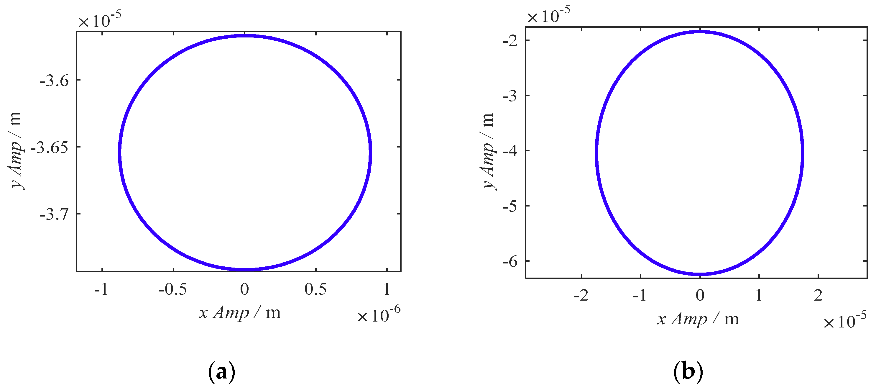
μ = 0.2. The axis orbits of normal and cracked rotors are compared in
Figure 2.
It can be seen that the normal rotor’s axis orbit is a standard circular trajectory, and the cracked rotor’s axis orbit is approximately a circular trajectory. It is shown that the axis orbit of the cracked rotor may be very similar to that of the normal rotor under the condition of certain system parameters. At this special time, if only the morphological characteristics of the axis orbit are used, it is easy to miss the diagnosis of cracks.
In order to increase the effect of axis orbit for distinguishing normal and cracked rotor, the new attribute (instantaneous whirling speed) are given to axis orbit, as shown in
Figure 3 and
Figure 4.
The plot diagram is shown in
Figure 5. First, the vibration signal should be obtained at equal intervals. Then, the sampling points during a whirling cycle in the X-direction and Y-direction can construct a discrete axis orbit, as shown in
Figure 3a and
Figure 4a. After that, the whirling center can be obtained, that is the square “□” in
Figure 3a and
Figure 4a. Next, the whirling center is set as the origin of the polar coordinates and the angle differences between the two adjacent sampling points are calculated. The angle difference is defined as the instantaneous whirling speed. Finally, the relative instantaneous whirling speed (RWS) is defined as the ratio of the instantaneous whirling speed to its maximum value and the RWS within a whirling cycle can be obtained, as shown in
Figure 3b and
Figure 4b.
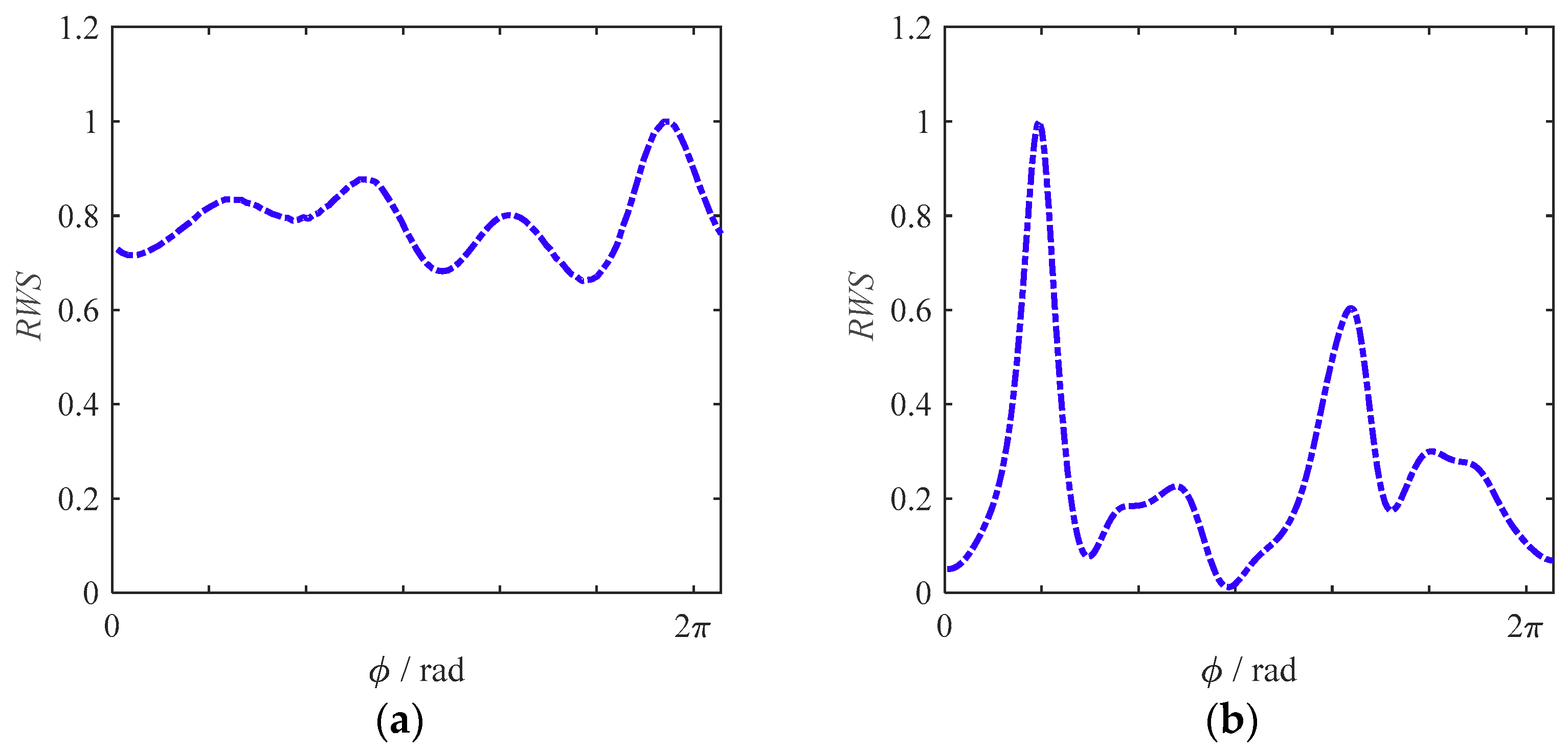
Figure 3a is a discrete axis orbit which is composed of equal time interval sampling points in a whirling cycle. As it can be seen from
Figure 3a that the sampling points are uniformly distributed, indicating that the whirling angles are equal in the same time interval when
μ = 0.
Figure 3b is the RWS within a whirling cycle (
). In
Figure 3b, it can be seen that the RWS of a normal rotor system is constant.
The discrete axis orbit and RWS when
μ = 0.2 are shown in
Figure 4. In
Figure 4a, it can be seen that the distribution of the sampling points in the discrete axis orbit of the cracked system is extremely uneven, and the sampling point is very dense near the position 4. In
Figure 4b, it has four fluctuations in the RWS in a whirling cycle. At position 1, RWS is at the local maximum value. Then RWS decreases from position 1 to position 2, reached the local minimum value at position 2. After that, RWS increases from position 2 to position 3, reached the local maximum value at position 3. From position 3 to position 4, RWS decreases again, and the minimum value occurs at position 4. The RWS varies transiently in a whirling cycle.
The above analysis shows that the addition of this new attribute significantly increases the effect of axis orbit for distinguishing normal and cracked states of rotor systems.
In order to study the application effects of RWS in experimental data, the vibration response test of a rotor system is carried out on the Bently KR4 Rotor Test Rig. The parameters of the experiment are the same as that of [
30]. As showed in
Figure 6, the rotor test rig mainly includes speed controller, motor, shaft, and base. The data acquisition equipment mainly includes eddy current displacement probe, signal regulator, and DAS (data acquisition system). The controller supplies power to the motor and controls the speed of the motor. The displacement probe collects the lateral vibration signal of the shaft, and is connected with DAS through the signal regulator.
The displacement signals in two directions (x and y) are acquired through the displacement probes, and the curves of RWS are plotted according the diagram in
Figure 5. As shown in
Figure 7, the RWS curve of the system with no rotor cracks (
Figure 7a) fluctuates in a small range but the RWS curve of the system with rotor cracks (
Figure 7b) fluctuates in a wide range. The RWS shows distinguished differences between normal and cracked rotors and that is qualitatively consistent with the simulation results as shown in
Figure 3b and
Figure 4b. On the other hand, the real rotor system is not an ideal normal system and has many differences with the system simulated by the dynamic model, suggesting that the RWS of experimental data is quantitative different with that of the simulated system. The RWS of a normal real system is not a constant like that shown in
Figure 3b but fluctuates in a small range.
The comparison results show that RWS can distinguish the normal and cracked states of real rotor systems. However, real rotor systems inevitably exhibit a certain extent of compound faults, such as misalignment, oil whirl, rubbing, and other faults, which may lead to the confusion of instantaneous whirl characteristics.
4. The Qualitative Mechanism Explanation
To further understand the cause of this transient characteristic, this section studies the relationship between the breathing effect of the crack and the transient variation characteristics of the RWS with regard to the work of the additional stiffness excitation.
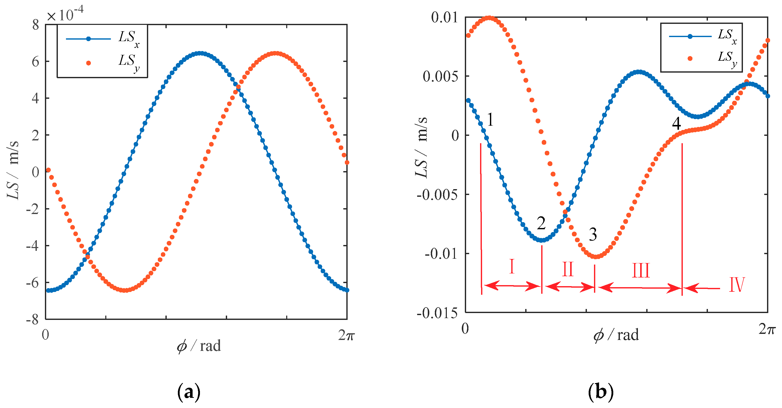
First, the line speed is introduced as the intermediate state variable. The whirling speed can be decomposed into the linear speed
LSx and
LSy along the X-direction and Y-direction respectively. The line speeds of the normal rotor system and the cracked rotor system are shown in
Figure 8. In
Figure 8a, it can be seen that the line speeds
LSx and
LSy of the normal rotor are standard sine curves, and there is a 90° phase difference between these two curves. Therefore, the whirling speed of the synthetic motion is a constant, as shown in
Figure 3b. However, in
Figure 8b, the line speeds of the cracked system are not the standard sine curve anymore. At position 4, the line speeds
LSx and
LSy are close to 0. So, at this time, the whirling speed of the synthetic motion reaches the minimum value, as shown in
Figure 4b.
In the steady state response of forced vibrations, the line speeds are mainly controlled by the mutual transformations of the kinetic energy and the potential energy. However, in the cracked rotor system, the non-uniform work of the additional stiffness excitation leads to the distortions of the line speed curves. In
Figure 4b, it can be seen that the RWS has two maxima and two minima. The change mechanism of these four special positions will be analyzed in the following part.
Equation (1) can be transformed into Equation (3):
Compared to the normal rotor system, additional stiffness excitation forces of cracked rotor system are shown in Equations (4) and (5):
Figure 9a shows the curves of the additional stiffness excitation forces
FX and
FY within a whirling cycle. In
Figure 9b,
Px and
Py are the instantaneous power of the additional stiffness excitation forces.
At position 1, from
Figure 8b we can see that the line speed
LSx close to 0, and the line speed
LSy reaches the maximum value at this time. Therefore, in
Figure 4b, the relative whirling speed of the synthetic motion closes to 1. In this paper, position 1 is used as the reference position of relative whirling speed.
From position 1 to position 2 (process I), as shown in
Figure 9a, the additional stiffness excitation forces are close to 0. Therefore, in
Figure 9b, the instantaneous powers of additional stiffness excitation forces are close to 0. Therefore, the linear speeds are determined by the conversions of the kinetic energy and potential energy. It can be known from
Figure 4a that the kinetic energy is turned into the potential energy in Y-direction during this process, and the line speed
LSy is close to 0 in the end. On the other hand, in X-direction, the potential energy is turned into the kinetic energy, and the line speed
LSx reaches the negative maximum value in the end which has been shown in
Figure 8b. However, the maximum value of the line speed in the X-direction is less than that in the Y-direction. Therefore, at position 2, the RWS of the synthetic motion is less than that at the reference position 1, thus the first minimum value appears in
Figure 4b.
From position 2 to position 3 (process II), it can be known from
Figure 4a, the potential energy is turned into the kinetic energy in Y-direction, and the line speed
LSy reaches the negative maximum value. In X-direction, the kinetic energy is turned into the potential energy, and the line speed
LSx is close to 0 in the end, which has been shown in
Figure 8b. However, the maximum value of the line speed in Y-direction is larger than that in the X-direction. Therefore, at position 3, the second maximum value of RWS of the synthetic motion appears in
Figure 4b.
From position 3 to position 4 (process III), the line speed in Y-direction tends to be 0 and the line speed in X-direction tends to be the positive maximum value. However, as it is shown in
Figure 9b, at this time the additional stiffness excitations do negative work in the X-direction, which prevents the line speed from following the normal change rule, and the line speed
LSx increases at the beginning and then decreases, as it is shown in
Figure 8b. On the other hand, the additional stiffness excitations do positive work in Y-direction, and the total power is less than that in X-direction. Therefore, the distortion of line speed
LSy is not significant. Eventually, this leads to the RWS of the synthesis motion to reach the minimum value in position 4, as shown in
Figure 4b.
From position 4 to position 1 (process IV), it should be that the line speed in Y-direction tends to be the positive maximum value and the line speed in X-direction tends to be 0. However, as shown in
Figure 9b, the additional stiffness excitation do positive work in X-direction at this time. This causes the line speed
LSx to increase at the beginning and then decrease, as shown in
Figure 8b. On the other hand, the additional stiffness excitations do negative work in Y-direction, and the total power is less than that in the X-direction. Therefore, the distortion of line speed
LSy is not particularly significant except the slow increasing speed of
LSy, as shown in
Figure 8b.
The above qualitative analysis shows that the work of the additional stiffness excitations affects the normal transformation rule between the kinetic energy and the potential energy of the rotor system, resulting in the distortion of the line speed and finally making the relative whirling speed which is synthetized by the line speed vary transiently. The explanation of transient characteristics can deepen the understanding of the dynamic characteristics of the cracked rotors.
6. Conclusions
In this paper, a new concept of instantaneous whirling speed of axis orbit is defined and studied by a Jeffcott rotor model. The instantaneous whirling speed is a new attribute of axis orbit and a new perspective for the vibration analysis of cracked rotors. The addition of this new attribute significantly increases the effect of axis orbit for distinguishing normal and cracked rotor systems.
The characteristic analysis shows that the relative whirling speed (RWS) of a cracked rotor system varies transiently and appears two maxima and two minima in a whirling cycle. The mechanism qualitative analysis shows that the transient variation of the RWS is caused by the influence of the work of the additional stiffness excitation on the normal conversion between kinetic energy and potential energy. In addition, the minimum value of the RWS decreases linearly with the increase of the crack depths, which can be a potential monitoring index for the severity of cracks.
The explanation of the transient characteristics of axis orbit can increase the understanding of the dynamic characteristics of cracked rotors. The new analysis perspective and the new diagnosis index are potential supplements to the crack diagnosis.
As we all know, most diagnostic methods and indicators have their applicable conditions or limitations, and so do the methods in this paper. First, the instantaneous whirling speed is a new additional attribute of axis orbit, thus this index is effective for steady-state rotor systems; hence, it is difficult to obtain the approximate circular axis orbit for unsteady rotor systems. Second, when compound faults exist, such as misalignment, oil whirl, rubbing, and other faults, these may lead to the confusion of instantaneous whirl characteristics, resulting in misdiagnosis of crack faults. In view of this, more types of diagnostic indicators should be studied to complement each other and improve the accuracy of the crack diagnosis.


