Article

Improving Accuracy and Reliability of Bluetooth Low-Energy-Based Localization Systems Using Proximity Sensors

by
Marcin Kolakowski
Institute of Radioelectronics and Multimedia Technology, Warsaw University of Technology , Nowowiejska 15/19, 00-665 Warsaw, Poland
Appl. Sci. 2019, 9(19), 4081; https://doi.org/10.3390/app9194081
Submission received: 29 August 2019 / Revised: 18 September 2019 / Accepted: 27 September 2019 / Published: 30 September 2019
(This article belongs to the Special Issue Recent Advances in Indoor Localization Systems and Technologies)

Abstract

:
One of the functionalities which are desired in Ambient and Assisted Living systems is accurate user localization at their living place. One of the best-suited solutions for this purpose from the cost and energy efficiency points of view are Bluetooth Low Energy (BLE)-based localization systems. Unfortunately, their localization accuracy is typically around several meters and might not be sufficient for detection of abnormal situations in elderly persons behavior. In this paper, a concept of a hybrid positioning system combining typical BLE-based infrastructure and proximity sensors is presented. The proximity sensors act a supporting role by additionally covering vital places, where higher localization accuracy is needed. The results from both parts are fused using two types of hybrid algorithms. The paper contains results of simulation and experimental studies. During the experiment, an exemplary proximity sensor VL53L1X has been tested and its basic properties modeled for use in the proposed algorithms. The results of the study have shown that employing proximity sensors can significantly improve localization accuracy in places of interest.

1. Introduction

One of the biggest challenges that modern societies might face in the coming years is the aging of their populations. According to the European Commission report [1], the projected percentage of people aged 65 or higher in 2070 will be 42.1%, while in 2016 it was 25%. Additionally, the number of working-age persons for every person aged over 65 will fall from 3.3 to 2. It means that the traditional care system consisting in young, healthy people caring for the older ones will become ineffective. Therefore, there is an urgent need for solutions, which will support the elderly persons care and significantly reduce caregivers workload.
The above problem can be partially solved by prolonging elderly people’s independent living by using modern Internet-of-Things technological solutions. Ambient and Assisted Living (AAL) programme supports their development by funding various projects aiming to improve older people’s health. Among many AAL projects, there are solutions intended to support elderly people living alone at their homes. Their main goal is to reduce the burden of the caregivers and allow many older people to independently live at their homes for as long as possible [2].
The designed and implemented AAL platforms are usually comprised of a set of sensors and devices, which are used to monitor an older person’s health state and behavior and help them in daily tasks. One of the functions allowing to monitor a user’s activity and behavior is user localization, which is usually delivered by a localization system being a part of the platform [3]. The localization systems used in the AAL platforms should meet several requirements. First of all, their accuracy should be high enough to provide the caregivers with reliable data to detect abnormal behaviors [4] or life threatening situations. For example, the localization data should allow to detect presence near vital spots such as near a gas stove or in a shower, to properly react in case of the prolonged, unusual and possibly dangerous activities. Secondly, it should be energy efficient to avoid frequent charging of system devices. Unfortunately, meeting both of these requirements using conventional solutions is often hard.

1.1. Indoor Localization Systems

Conventional radio indoor localization systems can be divided into two groups based on the type of used signals: narrowband systems and ultra-wideband (UWB) systems. Narrowband systems, which usually use widely spread standards (e.g., WiFi [5] and Bluetooth [6]) typically allow to localize the user with accuracy from one to several meters. UWB-based solutions [7] are much more accurate. Their localization accuracy can be as high as a dozen centimeters, but since the employed technology is not as known as than the aforementioned, they are less popular.
In the UWB positioning systems [7], the users are usually localized based on the time of arrival measurements of signals transmitted from the localized tags to the system infrastructure. Due to the short duration of the UWB signals (less than 1 ns), the time measurements can be performed with a resolution as high as 15.65 ps [8], which under the right conditions, can allow for precise and accurate localization. The two typically used localization methods in the UWB based systems are Time of Arrival (ToA) and Time Difference of Arrival (TDoA).
In Time of Arrival-based UWB systems [9] users location is derived based on the signal propagation times between the localized tag and the anchors comprising the system infrastructure. Range to the anchor is usually measured using the Two-Way Ranging procedure (TWR) which consists of exchanging packets between the tag and the anchor, noting their transmission and reception times [9]. The main advantage of this method is that, since the distance between the tag and each of the anchors is measured independently, anchor synchronization is not needed. On the other hand, ranging with each of the anchors on its own takes time and in case of extensive packet exchange, the infrastructure’s radio interface might become cluttered, which would limit the number of localized tags.
The Time Difference of Arrival method consists of localizing the user based on the difference of times, at which the anchors receive signals transmitted from the tag [10]. Typically, the only transmitting devices in this method are the tags, which helps to organize the transmission and allows to achieve higher system capacities when compared to ToA. The main problem with implementing TDoA is the requirement to achieve accurate and reliable anchor synchronization. In commercial systems, it is usually done by transmitting synchronization signals to the anchors with cables [11] but can also be achieved wirelessly by adding another reference anchor to the system infrastructure [10].
Both ToA and TDoA allow for precise localization in Line-of-Sight propagation conditions. The typically obtained accuraccies are at the level of a dozen centimeters [12]. When the propagation occurs in Non-Line-of-Sight Conditions (NLOS) the accuracy is usually lower.
Localization in narrowband systems is typically based on measurements of Received Signal Strength (RSS). In tracking and monitoring systems, where the transmitting tags are being localized, they are usually performed by the anchors. Those systems usually employ well known and widely spread standards such as WiFi or Bluetooth (more recently Bluetooth Low Energy BLE [13,14]). Most of the systems localize the users with one of two methods: fingerprinting or RSS ranging.
Fingerprinting is a method which consists of comparing the signal levels received by the anchors with a previously prepared radio map [14] containing information on signal levels received from particular places. Besides its easy implementation, the main advantage of the method is that it does not require any information on a system infrastructure placement or location. Unfortunately, achieving high accuracy localization demands preparing accurate high-density radio maps, which is usually done manually by placing the tag in points distributed in the area and storing received signal level values. Such a radio map is valid only for a specific configuration of a propagation environment and every change, such as moving a piece of furniture, may negatively impact a system’s accuracy. Radio map creation can be sped up using crowdsourcing [15] or interpolation [14], but since they still require performing some measurements, it would be hard to implement fingerprinting in a home environment.
Systems using RSS ranging are much easier to deploy. In that method, the user is localized by estimating their distance from the anchors based on a propagation model. The accuracy of the method depends on how accurately the assumed model reflects complex propagation conditions of the deployment area. Typically, the systems use simple models such as path loss exponentials [6] or multi-walls [16].
Narrowband systems average localization errors typically does not go below one meter. The accuracy highly depends on a place where the system is deployed and the number of anchors comprising the infrastructure. In apartments with extensive furniture, propagation models might not properly reflect the real conditions, and the accuraccy might suffer. Thus, the mean errors of the solutions found in the literature cover a broad range of 1–2 m [6] to 4–6 m [14].
A localization technique, which deserves attention is the Angle-of-Arrival (AoA). It can be used in both ultra wideband and narrowband systems and consists of estimating the directions from which the signals transmitted by localized object reach system anchor nodes. It can be done by rotating a directional antenna [17] or analyzing phase differences using antenna arrays [18]. The method does not require maintaing precise synchronization of the infrastructure [19] and allows to achieve results of accuracy comparable to RSS-based methods (average error of few meters) [20].
The localization accuracy that is possible to achieve with UWB-based systems is much higher than in case of narrowband WiFi or BLE solutions. Unfortunately, energy consumption of UWB devices is on a relatively high level. For the ToA-based system described in [9], it was estimated that the tag would work without recharging for 74 h if it were powered with 6000-mAh battery pack. In case of wearable devices, which usually use smaller batteries this time would be even shorter. BLE is more energy efficient. In case of BLE-based systems, in case of rare transmission tags, working times could reach 2 years powered by a coin battery. Moreover, due to the UWB technology being less popular and widespread, it is much more expensive and the overall cost of the localization system could be too high for the majority of older persons. That would make BLE a preferred choice for AAL solutions, but since its localization accuracy might not be enough for some services, it should be improved. It can be done by using hybrid localization methods combing measured BLE RSS with results obtained using different technologies.

1.2. Hybrid Localization Systems

In hybrid localization systems, user localization is computed based on different types of measurement data obtained using one or more various technologies.
The first group of hybrid localization systems are systems in which the user is localized using one technology based on various signal factors. Most notable examples combine typical measurements of RSS or TDOA with direction estimation AoA. In [21], a simple single device localization system is presented. The device uses RSS measurements to estimate a distance from the localized object and AoA to estimate direction, in which it is located. Such approach allows to minimize the number of reference anchor nodes to one. An interesting example of AoA usage in hybrid localization schemes is presented in [22], where a hybrid TDOA/AOA Extended Kalman Filter based algorithm for UWB localization system is described and tested. Another hybrid combination is RSS/TDOA, which can be used in WiFi-based systems [23].
In the second group of hybrid localization solutions, the users are localized using two or more different technologies. A very popular combination is fusing results obtained using the radio part with data from inertial measurement units. In [24], smartphone results from inertial sensors and magnetometer are used to support BLE-based fingerprinting. The presented solution allowed to localize the robot in places, where there was no coverage of BLE anchors, and quality of the radio map was poor. In [25], IMU senors were used for movement direction and gate analysis. The additional data allowed to significantly improve BLE positioning accuracy. A similar approach was taken in [26], where a single accelerometer was used for gait analysis, which allowed to improve localization accuracy in a UWB system.
Another large group is that of hybrid systems mixing two or more radio technologies. In [27], an asset tracking system using WiFi and Bluetooth is presented. It uses WiFi fingerprinting for early, rough asset localization and when the user gets closer, localizes it with greater accuracy using BLE trilateration. The same combination was used in a system deployed in a university library [28]. Here, the users were localized using BLE and WiFi fingerprinting. The system utilizes the fact that due to different anchor placement and propagation conditions, accuracy of the radio maps for BLE and WiFi varies in the same places. The localization errors for both maps are estimated during the map creation. During normal system operation the users are localized using both technologies concurrently and the more probable result is chosen. Another combination of technologies is BLE-UWB. In [29], UWB was used periodically to improve BLE-based localization. In [30], it was used in the process of radio map creation, which consisted in gathering points for the BLE radio map while localizing the user using UWB and then interpolating the missing parts based on the fitted exponential propagation model.
Solutions combining radio technologies with other types of sensors are much less common. In [31], a system concept, where the users are roughly localized using BLE and then tracked with vision systems is presented. Another example is [32], in which WiFi and ultrasound-based hybrid fingerprinting is presented.
An interesting type of sensors, which is not that popular and could be used in hybrid localization, are proximity and ranging sensors. They are usually used in robotics for SLAM (Simultaneous Localization and Mapping) but some examples of their use for localization can also be found. In [33], the sensors are used to form an array monitoring a small area of 600 × 300 mm dimensions. The sensors are used to track a round object moving around on a robot. The localization errors are very low and below 1 cm. Simulation of another example of a proximity sensor network is presented in [34].
The described proximity or ranging sensors network solutions would allow for easy device-free localization. Unfortunately, deploying such systems would require placing a large amount of sensors in fixed places, which makes them practically difficult to use in home environments. However covering with them selected spaces would not be problematic. Although, such sensors could be a good addition to radio-based systems, the author have not found any examples of employing them in hybrid localization schemes.
The paper presents a novel hybrid localization concept combining Bluetooth Low Energy with ranging sensors. The presented solution is the effect of the works started in [35], where a concept was briefly described and tested with very simple experiments. The proposed system concept is intended mainly for indoor user localization in AAL solutions. The user is localized using a BLE system, which is supported with a few singular proximity sensors placed in the areas, where BLE-based localization is less accurate or are important from older person’s safety point of view (e.g., a shower, near a stove). The results from both parts are fused using two types of hybrid localization algorithms. The presented concept was tested with simulations and experiments conducted in a typical fully furnished flat. The paper also includes the results of experimental assessment of VL53L1X [36] proximity sensor properties.

2. Hybrid Localization Concept

The typical received signal strength-based positioning systems, due to difficult and complex multipath propagation environments typically present indoors, do not allow for very accurate and reliable localization. Localization errors are particularly high at the edges of the area covered by the system or in closed spaces such as toilets or bathrooms. It comes from the fact that the propagation between the localized devices and most parts of the system infrastructure occurs under OLOS (Obstructed Line-of-Sight) or NLOS (Non Line-of-Sight) conditions, which introduce significant signal attenuation. The concept proposed in the paper consist in additional coverage of those and other vital places with proximity sensors.
Proximity sensors are small and cheap devices, which allow to detect presence and measure distance from objects located at moderate distances up to a few meters. Although it is possible to use them for distance measurement, they should not be mistaken with much more advanced laser distance meters. Proximity sensor field of view typically has a shape of a conical beam covering an angle up to a few dozen degrees, whereas laser distance meter is much more directional.
An exemplary scenario of the proposed hybrid concept use is presented in Figure 1.
In the proposed system concept, the localization system consists of three parts:
  • a tag, which is worn by the user
  • an infrastructure comprising a set of BLE anchors and proximity sensors
  • a system controller
The system operates in the following way. The tag, which is worn by the user, repeatedly sends BLE packets in the advertisement channels. The anchors receive them and measure the RSS (Received Signal Strength). Meanwhile, the proximity sensors perform independent, periodical distance measurements. Results from the infrastructure are sent to the system controller, which is an application running on a regular PC or a dedicated server and is responsible for position determination. The results can be exploited by an external system delivering services to monitored persons and their caregivers. For example, in the IONIS project [37] cloud-based solution performs these functions. The system controller manages the localization system infrastructure. In case of an anchors or tags failures (that are reported by anchors or detected if the communication with devices is lost), the alert message is sent to the cloud.
For most of the time, a user’s position is derived using BLE power measurement results only (Figure 1a). When the user steps into the area covered by one or more proximity sensors and their presence is detected, a hybrid algorithm combining BLE and ranging results is used. Unfortunately, since the proximity sensors have no way of discriminating between different users and the presented solution is intended for locating on individual only. That problem could be resolved by prior localization of the users based on BLE only and checking which user is closer to the sensor. However, because of low BLE accuracy, this approach would not be dependable when the users are close to each other. Since the system is intended for use by an older person living alone, it is not a major drawback.
In the presented system architecture, the BLE anchors and the proximity sensors are separate devices, but it is possible to integrate them. It would simplify communications with the system controller and greatly reduce number of power supplies needed by the infrastructure. However, such an approach is not the best for localization. A proximity sensor maximum range is usually limited to a few meters and it would be best to orient its beam parallel to the ground to maximize the covered area. It would also mean placing the sensors in lower positions, so the signal could easily reflect off the localized person. However, such placement might not be the best choice from a BLE signal propagation point of view, because of a large number of obstacles present at waist height.

3. Localization Algorithm

In the proposed concept, the user is localized based on two types of data coming from the system infrastructure: RSS measurements performed in BLE radio interface and ranging results from proximity sensors. The concept assumes use of different algorithms for the possible scenarios of user localization, which are:
  • the user is not in the area covered by any of the proximity sensors and is localized using only BLE RSS measurement results (Extended Kalman Filter based algorithm),
  • the user’s tag is off or disabled and he is localized based solely on ranging data,
  • the user wears the tag as normal and is present in at least one of the proximity sensors beams (hybrid algorithm in one of two versions: loosely or tightly coupled).

3.1. BLE Based Algorithm

The first localization method used in the proposed system is an Extended Kalman Filter (EKF)-based algorithm [38] utilizing solely BLE power measurement results. The main advantage of the EKF over traditional geometry-based methods such as trilateration is that the result of the EKF if a combination of the result calculated using performed measurements and the prognosed location based on the previous user position. It allows to mitigate abrupt changes of signal level, which often occur in the multipath environments. Additionally, the number of the results that can be used for localization is not limited. In EKF it is also possible to take into consideration higher variance of the results obtained by the anchors, which are far away from the tag. In the algorithm, the localized user is treated as a dynamic system and the state at the current moment k is described by a vector:
x k = x v x y v y
containing the user’s current coordinates: x, y and velocity components: v x , v y . The vector does not include information on the z coordinate (height, at which the localized tag is worn) and corresponding velocity. All of the algorithms presented in the paper are intended for 2D localization and z value is one of the algorithm parameters.
The EKF is an iterative algorithm consisting of two phases: time-update phase and measurement-update phase. In the time-update phase, the localization of the user at the current moment k is predicted based on the location calculated for the previous moment ( k 1 ) and the assumed movement model. The equations comprising this phase are:
x ^ k ( ) = F x ^ k 1 ( + )
P k ( ) = F P k 1 ( + ) F T + Q
where:
  • x ^ k ( ) is the predicted state vector value,
  • x ^ k 1 ( + ) is the state vector value obtained in the previous EKF iteration,
  • P k ( ) and P k 1 ( + ) are the state covariance matrices of the above vectors,
  • F is the state transition matrix containing the movement model,
  • Q is the process noise covariance matrix.
The movement model used in the algorithm is the Discrete White Noise Acceleration (DWNA) [39] model, in which the movement between the analyzed moments is uniform and linear and acceleration is treated as process noise. For the DWNA, matrices F and Q have the following form:
F = 1 Δ t 0 0 0 1 0 0 0 0 1 Δ t 0 0 0 1 Q = Δ t 2 1 2 Δ t 3 0 0 1 2 Δ t 3 1 4 Δ t 4 0 0 0 0 Δ t 2 1 2 Δ t 3 0 0 1 2 Δ t 3 1 4 Δ t 4 σ a 2
where Δ t is algorithm update rate and σ a 2 is acceleration variance, which is usually assumed to be in the range of 0.5–1 of a moving man’s maximum acceleration.
The obtained predicted localization x ^ k ( ) is updated with measurement results in the measurement-update phase. This phase consists of estimating measurement results, which would be obtained for the predicted localization based on assumed sensor model (BLE anchor model). The predicted measurement results are then compared with the actual values measured by the infrastructure. The set of equations making this phase is as follows:
K k = P k ( ) H k T H k P k ( ) H k T + R k 1
x ^ k ( + ) = x ^ k ( ) + K k z k h k ( x ^ k ( ) )
P k ( + ) = I K k H k T P k ( )
z k = R S S 1 R S S n
h k ( x k ) = R S S 1 ( x k ) R S S n ( x k )
where:
  • z k is the measurement vector containing RSS ( R S S n ) measurement results,
  • h k ( x k ) is the sensor model used to calculate measurement values which would be obtained for the predicted tag localization,
  • H k is a linearization of the sensor model,
  • K k is the Kalman gain ,
  • R k is the measurement covariance matrix.
In the proposed algorithm, the power levels received by the anchor (sensor model) were calculated using the exponential path loss model:
R S S n ( x k ) = R S S 0 10 γ log 10 d ( x k ) d 0
where:
  • R S S n is the signal power received by the anchor n,
  • d is the distance between the anchor and predicted tag localization,
  • R S S 0 is the received power at the reference distance from the tag d 0 ,
  • γ is the path-loss exponent.
The prediction updated with the measurement results is the final result of the algorithm iteration and is used as the input for the next EKF iteration.

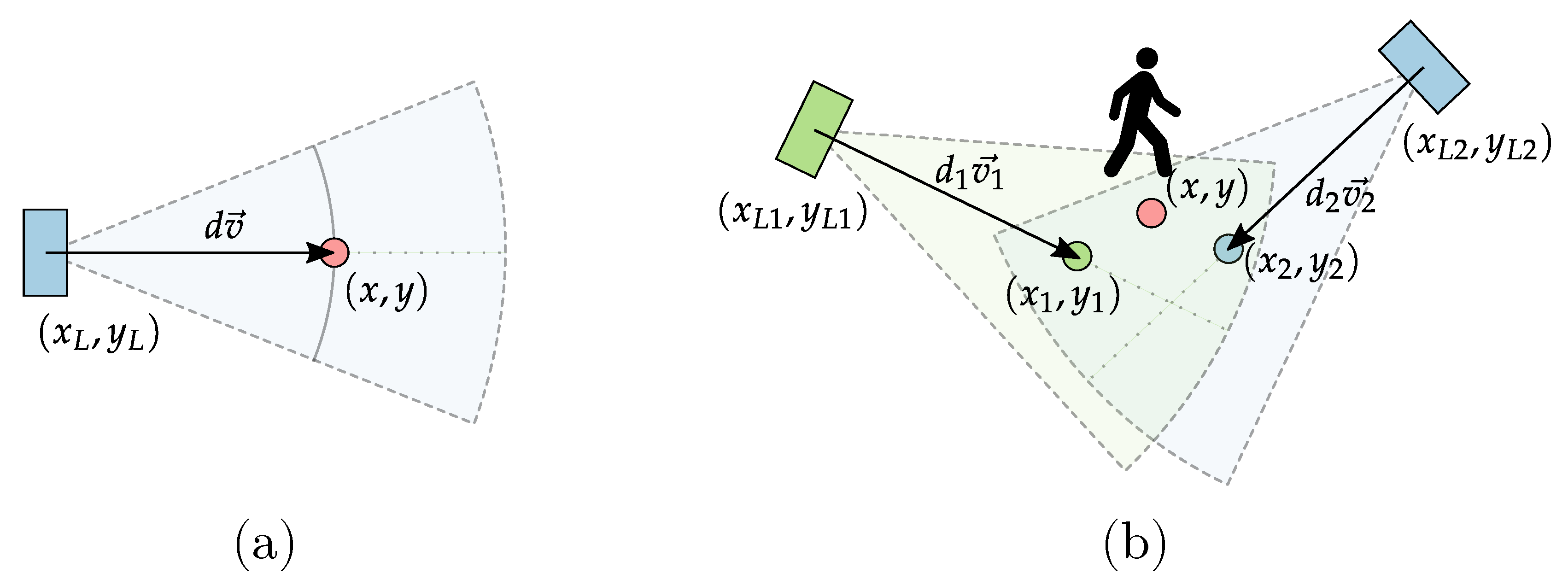
3.2. Proximity Sensors Based Localization

The second proposed localization method consists of locating the user based on ranging results only. The basic idea behind the algorithm is illustrated with Figure 2.
When the result from only one sensor is available (Figure 2a) it is difficult to precisely localize the user—his location can only be expressed as an arc located at the measured distance. Since the system requires results as exact x-y coordinates, the user is roughly localized in the center of the sensor beam at the measured distance.
In this situation, when the user is in the range of two or more proximity sensors, his/her location can be inferred more precisely. One of the most popular choices for localization in case of ranging measurements is the trilateration algorithm [14]. It consists of finding an intersection of two arcs corresponding to distances measured by the sensors. Here, since the user, from whom the signal is reflected is not very small, a situation in which those arcs intersect would be extremely rare and the trilateration algorithm would suffer. Here, an alternative, simplified method is used. In this method, the user is located by each of the sensors separately at the sensors’s main axes as presented in Figure 2b. Then, the obtained localizations are fused by calculating the weighted average:
x = i 1 σ i 2 x i i 1 σ i 2 y = i 1 σ i 2 y i i 1 σ i 2
where σ i 2 is the variance of the distance measurement performed by the sensor. Applying weights, which are inversely proportional to measurement variance allows to take into account the higher uncertainty of locations at bigger distances, which result from a lower level of the reflected signal received by the sensor and a longer arc due to a wide covered area. Assuming that all of the sensors are independent of each other, the variance corresponding to the computed localization can be approximated as:
σ 2 = 1 i 1 σ i 2
The obtained value would be the final result in case of localizing a user without the tag. In case of a presented hybrid solution, it will be an input to loosely coupled version of the hybrid algorithm.

3.3. Loosely Coupled Hybrid Algorithm

The first version of the hybrid algorithm used in the system is loosely coupled. It means that the user localization is calculated separately using both technologies and then fused. Localizations based on BLE power measurements and ranging are calculated using algorithms presented in Section 3.1 and Section 3.2 respectively. The obtained results are then fused using the following formula:
p = p B L E σ R A N 2 σ B L E 2 + σ R A N 2 + p R A N σ B L E 2 σ B L E 2 + σ R A N 2
where:
  • p B L E is the localization calculated based on BLE power measurements (6) and σ B L E 2 is the corresponding variance taken from covariance matrix P (7),
  • p R A N is the localization calculated based on ranging results (6) and σ R A N 2 is its variance (12).
When the localization calculated using BLE is very inaccurate, it is possible that the result obtained using the hybrid algorithm will be positioned outside the used proximity sensor beam. Since the sensor detected the user, it is almost certain that he/she is in its field of view. In such case, to improve algorithms accuracy, the obtained result is pulled to the closest point on the arc corresponding to the measured distance.

3.4. Tightly Coupled Hybrid Algorithm

In the tightly coupled version of the hybrid algorithm, raw measurement results from the BLE anchors and ranging sensors are fused. For this purpose, the EKF is used. The assumed models and implementation of the time-update and measurement phase are almost identical to the BLE-based EKF presented in Section 3.1 (1)–(7). The major differences are the forms of the measurement vector z and the sensor model h k ( x k ) .
z k = R S S 1 R S S n d 1 d n
h k ( x k ) = R S S 1 ( x k ) R S S n ( x k ) d 1 ( x k ) d n ( x k )
The measurement vector contains both RSS measurement results and measured distances. In the sensor model h k ( x k ) the RSS is estimated as in (10), whereas ranging results d n are estimated as the distance of the sensor from the predicted location.
The other difference is verification and correction of the predicted state vector value. As in the loosely coupled version, if any of the proximity sensors detect the user and the predicted location is outside the sensors beam, it is pulled to the closest point on the arc corresponding to the measured distance.

4. Simulations

4.1. Simulation Environment

The proposed hybrid localization concept and algorithms were tested with simulations. Simulations were performed using a simple simulator implemented in Python. The simulator allowed to specify test paths, which could be covered by a user during his daily activities and simulate measurements performed by BLE anchors and ranging sensors comprising the system infrastructure.
The Received Signal Strength (RSS) of the BLE signals measured by the anchors was modeled using the multi wall propagation model [16]. The model takes into account the topography of the area, where the system is located and introduces additional attenuation due to signal propagation through multiple walls. The model is described by the following dependence:
P R = P R 0 10 γ l o g 10 d d 0 + i = 1 I k = 1 K i L w i k + X σ 2
where:
  • P R is the power received by the anchor from the tag
  • P R 0 is the power received at the reference distance d 0 (1 m) (assumed −52 dB)
  • γ is the path loss exponent (assumed 2.4)
  • d is the distance between the tag and the anchor
  • I is the number of different wall types in the simulated area
  • K i is the number of walls of type i
  • L w i k is the attenuation due to k t h traversed wall of type i
  • X σ 2 is the log-normal random component present due to the shadowing effects and the receiver noise (3 dB standard deviation)
In the simulations, it was assumed that all of the walls are the same and introduce the same signal attenuation (2 dB).
The measured distance was simulated as:
d m = d + n ( d )
where:
  • d is the distance between the localized person and the sensor,
  • n ( d ) 
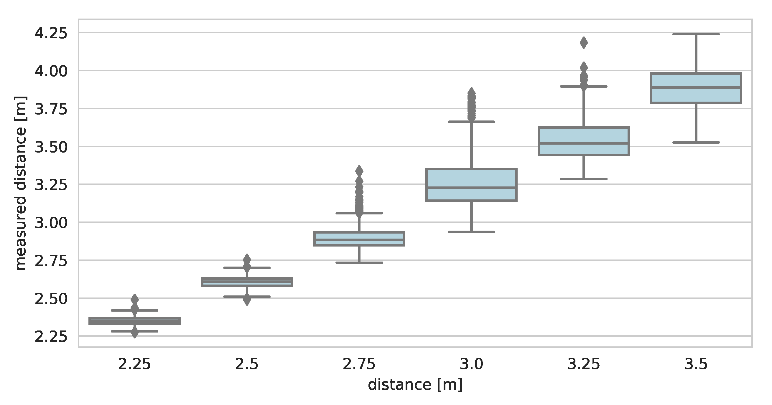
is the measurement white noise of standard deviation calculated based on standard deviation model. The assumed deviation model was: σ ( d ) = d 2 / 60 . According to the model, standard deviation rises with distance, which reflects less accurate measurements due to a lower level of reflected signals.
During the simulations, the sensors performed ranging only when the user was located in their beams. The areas covered by the sensors were modeled as conical beams of 30 width, and the maximum range of the sensor was set to 3.5 m.
The user was localized based on the generated results using three algorithms: EKF using RSS measurements and two hybrid algorithms proposed in Section 3.

4.2. Performed Simulations

The proposed system was simulated in an apartment consisting of few rooms. The simulations consisted in generating a set of simulated measurements for points distributed along two different test paths. It was assumed that the person was walking with a speed of 1.2 m/s, which is typical for the adults. The BLE RSS values and distances were measured five times per second. The layout of the apartment, the placement of the system infrastructure and both of the test paths are presented in Figure 3.
The BLE system infrastructure consisted of nine anchors distributed in the apartment. They were placed in such a manner that in each of the rooms, at least one anchor was present. The anchors were fixed to the outer walls, which allowed to evenly cover the whole apartment. The number of used proximity sensors was different in both scenarios.
In the first simulated scenario, the user walked from room 1 to room 3 and then visited the kitchen, where he stood in front of the gas stove for 10 s, then he came back to room 1. In the scenario, five ranging sensors were used, two were placed in room 1, two in the corridor and one in the kitchen covering the area in front of the stove.
The second path included other rooms. The user started from room 1, then visited rooms 2 and 4 and went to the bathroom, where he stood in the shower cabin for 10 s. After that, he returned to room 1. In this experiment, nine proximity sensors were used, the first four were located in room 1 and the corridor as in the previous scenario. Additionally, two were placed in both bathroom and room 2 and one in room 4.
The localization results obtained for the first and second scenarios are presented in Figure 4 and Figure 5, respectively.
The accuracy of localizations calculated based on BLE RSS results only varies in the apartment. It is highest in the middle parts of the flat, whereas in the border rooms, the errors are significantly higher. It results from the fact that the signals transmitted from the tag located in those rooms propagate through multiple walls, which introduce significant attenuation. The obtained results are accurate enough to determine a room where the person is located, but nothing more. Using ranging sensors allows to improve localization accuracy in the border rooms, as well as in the corridor. As it can be seen, in case of a loosely coupled algorithm (Figure 4b) the system detects the prolonged presence in front of the gas stove. Results obtained with the tightly coupled version are less accurate (especially in the situation, where the results from only one proximity sensor are available).
In the second scenario, similar results were obtained. BLE-based localization accuracy is low in places, from which the tag transmitted signal propagates through multiple walls. In case of localization in the bathroom, where the propagation to all of the anchors occurs under NLOS conditions, it is difficult to determine the room where the user is located. As in the previous example, using ranging sensors allows to significantly improve localization accuracy. The results from both algorithms allow us to say that the user spent some time in the shower cabin. For tightly coupled algorithms, it was also observed that fusing BLE RSS with only one distance measurement might not be enough. Localization accuracy in room 4 is much lower than in case of the bathroom or the corridor, which are covered by two sensors.
The localization methods can also be compared by analyzing localization errors defined as the Euclidean distance between the calculated localization and the point, where the simulated user was present. A convenient way to do that is to use the Empirical Cumulative Distribution Function (ECDF). The ECDF curves for both of the scenarios are presented in Figure 6.
In both cases, using hybrid positioning allowed to improve localization accuracy. Localizing using only BLE RSS resulted in median erros of about 1.1 m in both scenarios. The best accuracy was achieved using a loosely coupled version of the hybrid algorithm—median error was 0.4 m for both scenarios. In case of the tightly coupled algorithm, localization accuracy was lower and median error was about 0.8 m and 0.55 m for scenarios 1 and 2, respectively.

5. Experiments

The proposed concepts and algorithms were verified with experiments performed in one of the Warsaw University of Technology laboratories and a typical fully furnished flat. The experiment consisted of two phases. First, an exemplary ranging sensor available on the market—VL53L1X by ST Microelectronics was tested to verify whether its properties allow for use in the proposed hybrid localization scheme. This part was conducted in laboratory rooms. The second part of the experiment consisted of using the aforementioned sensors and a BLE-based localization system developed within the IONIS project [37] to verify the proposed concept in an apartment.

5.1. Properties of VL53L1X Proximity Sensor

An example of a proximity sensor, which could be easily adapted for use in a the presented hybrid localization system concept is the VL53L1X chip produced by ST Microelectronics [36]. It is a small device, which consists of a 940 nm invisible Class 1 laser emitter, SPAD (Single-photon avalanche diode) receiving array and additional optical filters. The main advantage of the sensor is the fact that unlike typical infrared sensors, it employs Time-of-Flight (ToF) method for ranging, which according to the producer is supposed to ensure accurate distance measurement regardless of target’s color and surface reflectance [40].
The sensor’s properties, which are most important from the localization point of view are listed in Table 1 (the values come from VL53L1X datasheet [36]).
The sensor has a range of 4 m, which would be sufficient for indoor localization in typical apartments. Its field of view (FoV) is a conical-shaped beam, the width of which can be programmed in the range of 15–27 . Such property allows to tune the sensor and increase its selectivity. The measurement rate can also be programmed up to 50 Hz, which makes it possible to precisely match the localization rate of a radio subsystem. Additionally, the sensor is small and can be easily incorporated into the radio system’s anchor nodes.
It is worth noting that the values stored in Table 1 were obtained in particular conditions and for a specific target. As stated in the application note, the measurements were taken for charts of different reflectance, which covered the full sensor FoV. In case of measuring distance from a person, those values might be different. The proposed hybrid algorithms utilize some of the above values (maximum range, field of view). Therefore, to avoid errors resulting from assuming sensor parameters from data sheets, it is necessary to estimate those parameters for reflection from a human body.
The performed sensor tests consisted of evaluating its basic properties such as ranging bias, ranging standard deviation and sensor FoV. In the experiment P-NUCLEO-53L1A1 [41] modules consisting of two evaluation boards: STM32F401RE (nucleo microcontroller board) [42] and X-NUCLEO-53L1A1 (nucleo board expansion with up to three VL53L1X sensors) [43] were used. The module was programmed with the exemplary SimpleRanging application [44]. The application measured distance and sent it to the attached PC over USB. The sensor working mode was set to `long’, ranging rate to 10 Hz and the FoV to the default 27 width.
The first part of the experiment consisted of ranging from a person located at different distances and dressed in different clothes. The sensor was placed at waist level. The measurements were conducted on a sunny day in an office space under two different lighting conditions (blinds opened and closed). The obtained results were compared to the distance measured with an accurate laser distance meter. The distance measurements were conducted for the following persons:
  • person in a black shirt (blinds closed)
  • bare-chested person (blinds closed)
  • person in a white shirt (blinds closed)
  • person in a black shirt (blinds opened)
For each of the measurements ranging bias and standard deviation were evaluated. The gathered results were used to model bias and standard deviation with polynomial functions, which would be used in the hybrid localization algorithm. The distances measured with VL53L1X and estimated ranging bias values are shown in Figure 7. Ranging standard deviation is presented in Figure 8.
During the tests, the maximum range, for which it was possible to properly measure distance from a person was about 3.5 m. At close ranges, up to 2 m, the measures are very accurate and the bias does not exceed 0.1 m. For larger distances, it rises and for 3.5 m is higher than 0.3 m. The measures show no clear dependence on the reflective surface (clothing color) or lightning conditions. Therefore, it makes sense to model the bias and introduce the correction in the localization algorithm. Ranging bias was modeled with a third degree polynomial and the resulting curve was plotted in Figure 7b. The polynomial coefficients are stored in Table 2.
Ranging standard deviation also depends on the measured distance. For ranging from close objects, it is relatively small (lower than 5 cm for distances up to 2.5 m). At the edge of the sensor range, measurement noise is significantly higher—for 3.5 m, in case of the black clad man in a bright room, standard deviation approaches 0.2 m. Based on the measurement results, standard deviation was modeled as a third degree polynomial. The coefficients are stored in Table 2. Large ranging errors caused by high measurement noise can be clearly seen on a ranging results boxplot presented in Figure 9.
Large standard deviations at long distances might pose a problem in terms of accurate localization. As it can be seen, for distances over 2.5 m, ranging errors sometimes have few dozen centimeter magnitudes. Such high errors can easily lead to very inaccurate localization. Therefore, the proposed localization algorithms (proximity sensors based localization and hybrid algorithms) will utilize both the above fitted models to mitigate ranging bias and lower the impact of low accuracy measurements on the final localization result.
The second phase of the VL53L1X properties testing was measurement of the sensor’s FoV. The experiment was conducted in a bright, large (6×8 m) laboratory room. The test consisted of placing an A3 paper sheet attached to the utility cart in front of the sensor and moving it sideways till the sensor lost visibility of the object. The border positions at both sides were noted and the sensor’s actual FoV was evaluated.
For the conditions in the laboratory room and the tested object, the measured FoV was smaller than claimed in the application note. For distances up to 50 cm, they were very similar, whereas at 3 m, the difference in the width of the covered area was almost 80 cm.
Based on the measurement results, a model of FoV was created. Sensor FoV was modeled as the conical beam of 20.3 width. The measured and modeled FoV is shown in Figure 10.
The above results show that the VL53L1X meets the requirements to be used in the proposed hybrid localization scheme. The ranging results are accurate for close objects, and since the bias for large distances does not depend on lightning conditions and reflecting surface, it is easy to correct. The sensor FoV is wide enough to cover a significant area of typical rooms.

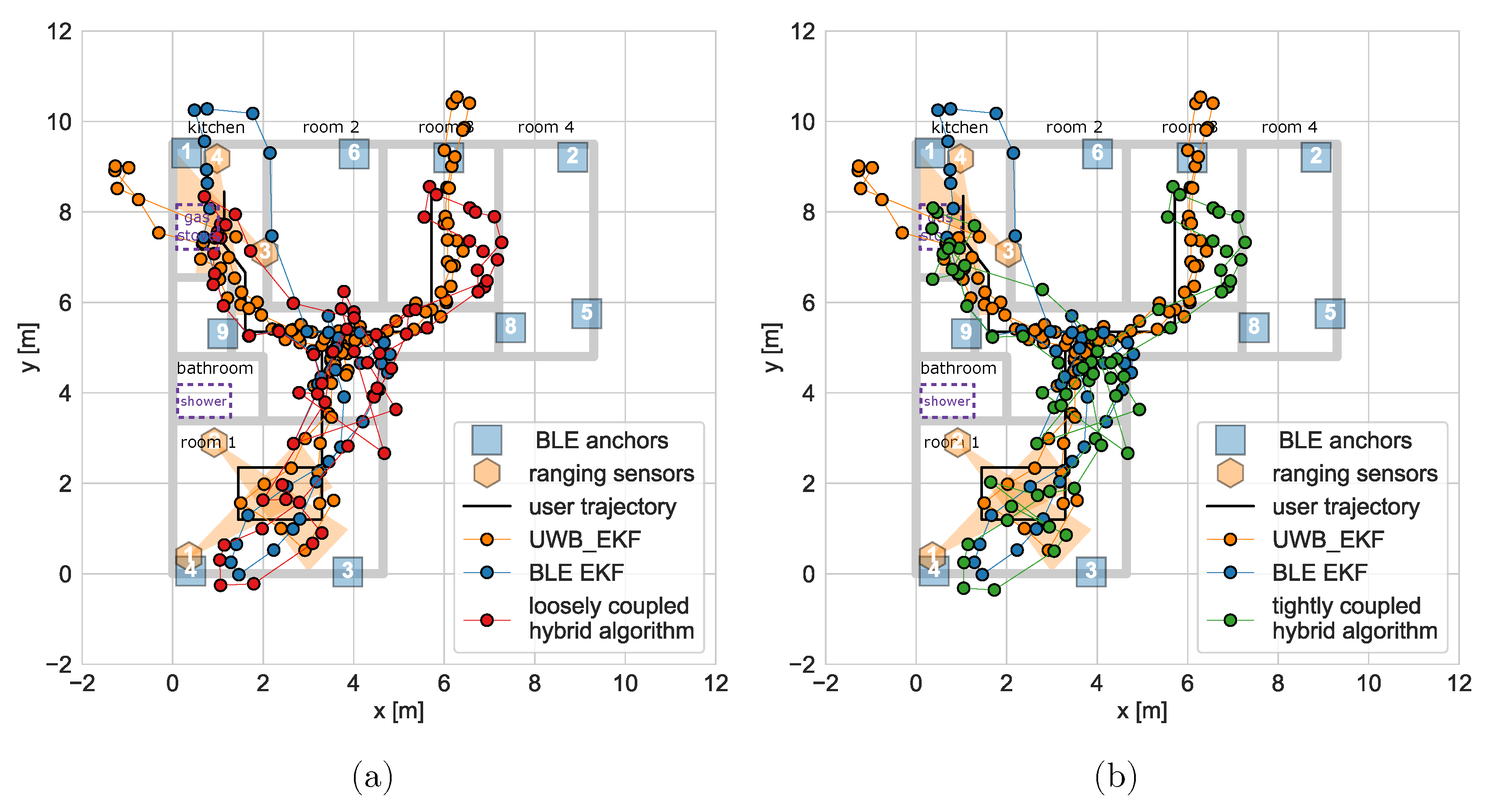
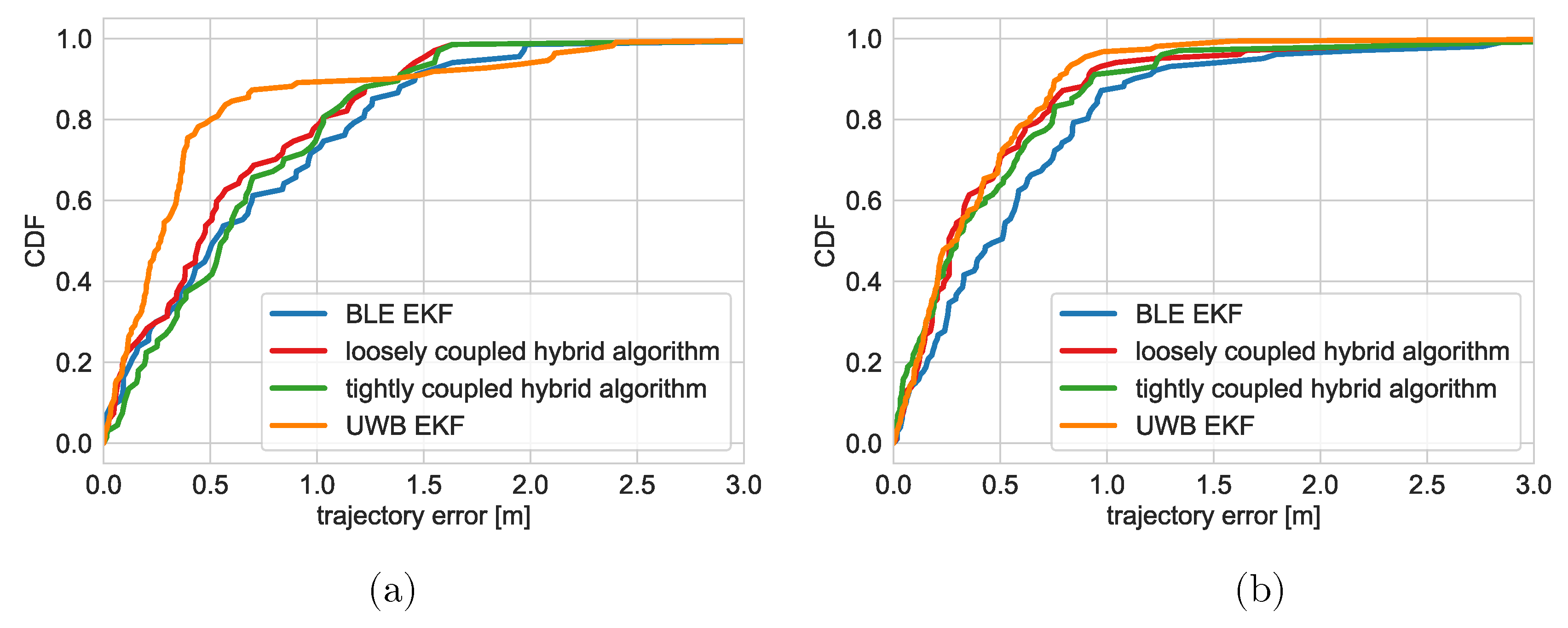
5.2. Hybrid Localization Concept Verification

The main part of the experiments was verification of the proposed concept using a BLE-based localization system and laser ranging sensors. The test was conducted in a typical, fully furnished flat, which was the flat modeled in the simulations. As in simulations, the experiment consisted of walking along two test paths and localizing the user using BLE-based and hybrid algorithms. Localization results were compared with the results obtained using a TDOA-based UWB positioning system developed at WUT during one of the earlier projects [10]. The layout of the apartment and places where the infrastructure elements were placed is presented in Figure 11.
The infrastructure used in the experiment comprised two parts: BLE positioning system and ranging sensors.
The positioning system consisted of nine BLE anchors fixed to the walls and one tag worn by the user. All of the devices were equipped with Laird BLE652 modules, which were programmed to broadcast five BLE packets per second. The received results were averaged per second to mitigate signal power fluctuations. The tag was worn on a lanyard.
As the proximity sensors P-NUCLEO-53L1A1 modules including VL53L1X sensors were used. The modules were placed at the height of 1.4 m, so that the beam was directed at person’s corpus. Ranging rate was set to 10 Hz, and the obtained distances were averaged per second to match BLE part localization rate.
The UWB-based localization system used as reference consisted of nine anchors, which were placed in the same places as the BLE-based infrastructure. In the system, the user was localized three times per second using an EKF-based algorithm utilizing TDOA measurement results [10].
The experiment consisted of walking along two test paths. In the first experiment, the user visited room 1, room 3 and the kitchen, where he stood in front of the stove for a few seconds. The second path included rooms 2 and 3 and the bathroom, where the user spent a few seconds in the shower cabin.
The collected measurement results were used to localize the user with the algorithms described in Section 3. The algorithms used were: EKF using only BLE RSS results, loosely coupled hybrid algorithm and tightly coupled hybrid algorithm. The results for both paths are presented in Figure 12 and Figure 13.
The obtained localization results are similar to those calculated during the simulations. In case of all tested solutions, the system’s accuracy is significantly lower in the border rooms, where most of the transmission occurs in NLOS conditions. It can especially be seen in the kitchen, where the user location estimated with both BLE and UWB based systems is outside the flat. Using ranging sensors in the kitchen allowed to localize the user in front of the stove. It did not have much effect in the living room, where the visualized path was still away from the reference. There were no significant differences in the results obtained using both algorithms.
For the second path, similar observations can be made. Using ranging sensors, visibly improved positioning accuracy in the bathroom and room number 2. The user is localized directly in the shower cabin, which was difficult using solely BLE (but was achieved using UWB). Additionally, the results are aligned close to the reference trajectory in room 2. Covering room 4 with one ranging sensor did not work very well. Since it was a single sensor and the covered area was small, there was no significant improvement in the accuracy.
The results obtained using both algorithms differ for localization under the shower. In case of the loosely coupled version, when the user entered the shower, his estimated locations are grouped in one point. For the tightly coupled version, due to high variance of RSS measurements, some of the results are located outside the bathroom.
The comparison of algorithm accuracy can also be performed based on Empirical Cumulative Distribution Function (ECDF) for localization errors. Since, during the performed experiment, the moving user was localized, it was difficult to precisely determine his true location for reference and calculate localization errors. Therefore, for accuracy comparison purposes, a trajectory error defined as the smallest distance between the localized point and the reference trajectory was used. The ECDF curves for calculated trajectory errors are presented in Figure 14.
For both of the paths, the most accurate results were obtained with the UWB-based localization system. In case of the first path, the difference was significant (median trajectory errors equaled 0.27 m for UWB equaled, 0.45 m for loosely coupled hybrid algorithm and 0.51 for BLE-based EKF). In some cases, UWB system did not allow for accurate localization. For about 10 percent of the results the trajectory error exceeded one meter. It might have resulted from multipath propagation (in the apartment there were three large wardrobes with mirror covered doors). For the second path, the difference between UWB and hybrid algorithms was negligible. In both cases, the obtained trajectory errors were smaller when using additional ranging sensors than in case of using BLE only. The CDF curves show that a loosely coupled version of the hybrid algorithm was more accurate than a tightly coupled one but the difference was not significant.
To conclude, the performed experiments have shown that using proximity sensors as an addition to BLE-based localization system allows to improve localization accuracy. The overall accuracy of the solution is lower than of the UWB based positioning systems, but given the higher cost and energy demands of the UWB based systems, the proposed concept might be a good alternative for use in some AAL solutions.

6. Conclusions

In this article, a concept of a novel hybrid localization system intended for AAL solutions is presented. The system combines Bluetooth Low Energy technology with ranging sensors. Ranging sensors have a supporting role and are used to additionally cover places, where the BLE-based localization is not accurate enough. In case when the system is used by the person living alone, it can be useful in some cases even if the person does not wear the tag. In such a case, the user would be localized only in places covered by the sensors, but even such information can be valuable from a caregiver’s point of view.
In the system, three types of localization algorithms can be used: an Extended Kalman Filter using only BLE results and two versions (loosely and tightly coupled) of the hybrid algorithm integrating results from both parts.
The proposed concept has been tested with simulations and experiments. Both have shown that the use of ranging sensors can improve localization accuracy in the covered areas. There were no problems with localizing the user directly in front of the stove or in the shower cabin, which was difficult using Bluetooth only. The results have shown that the best in terms of accuracy is the loosely coupled hybrid algorithm.
To conclude, the performed research has shown that the presented concept shows promise and could be efficiently implemented in the AAL platforms. The accuracy of the proposed solution could be improved by using ranging sensors, which would cover a larger area; for example, an array consisting of few VL53L1X sensors facing slightly different directions.

Funding

This work was financed by the National Centre for Research and Development, Poland under Grant AAL/Call2016/3/2017 (IONIS project).

Acknowledgments

I would like to thank the IONIS project team for making the localization system available for the performed test. I would like to also express my gratitude to Robert Kolakowski for his help in organizing and performing the measurement campaign.

Conflicts of Interest

The author declares no conflict of interest. The funders had no role in the design of the study; in the collection, analyses, or interpretation of data; in the writing of the manuscript, or in the decision to publish the results.

Abbreviations

The following abbreviations are used in this manuscript:
AALAmbient and Assisted Living
UWBultra-wideband
ToATime of Arrival
TDoATime Difference of Arrival
BLEBluetooth Low Energy
EKFExtended Kalman Filter
ToFTime of Flight
FoVfield of view
SPADSingle-photon avalanche diode
LOSLine of Sight
OLOSObstructed Line of Sight
NLOSNon Line of Sight
RSSReceived Signal Strength

References

  1. European Commission; Directorate-General for Economic and Financial Affairs; Economic Policy Committee of the European Communities. The 2018 Ageing Report: Underlying Assumptions and Projection Methodologies; OCLC: 1013458008; Publications Office of the European Union: Luxembourg, 2017. [Google Scholar]
  2. Dawson, A.; Bowes, A.; Kelly, F.; Velzke, K.; Ward, R. Evidence of What Works to Support and Sustain Care at Home for People with Dementia: A Literature Review with a Systematic Approach. BMC Geriatr. 2015, 15, 59. [Google Scholar] [CrossRef] [PubMed]
  3. Barsocchi, P.; Potortì, F.; Furfari, F.; Gil, A.M.M. Comparing AAL Indoor Localization Systems. In Evaluating AAL Systems Through Competitive Benchmarking. Indoor Localization and Tracking; Springer: Berlin/Heidelberg, Germany, 2011; pp. 1–13. [Google Scholar] [CrossRef]
  4. Lin, Q.; Zhang, D.; Chen, L.; Ni, H.; Zhou, X. Managing Elders’ Wandering Behavior Using Sensors-Based Solutions: A Survey. Int. J. Gerontol. 2014, 8, 49–55. [Google Scholar] [CrossRef]
  5. Yang, C.; Shao, H.R. WiFi-Based Indoor Positioning. IEEE Commun. Mag. 2015, 53, 150–157. [Google Scholar] [CrossRef]
  6. Cantón Paterna, V.; Calveras Augé, A.; Paradells Aspas, J.; Pérez Bullones, M.A. A Bluetooth Low Energy Indoor Positioning System with Channel Diversity, Weighted Trilateration and Kalman Filtering. Sensors 2017, 17, 2927. [Google Scholar] [CrossRef] [PubMed]
  7. Alarifi, A.; Al-Salman, A.; Alsaleh, M.; Alnafessah, A.; Al-Hadhrami, S.; Al-Ammar, M.A.; Al-Khalifa, H.S. Ultra Wideband Indoor Positioning Technologies: Analysis and Recent Advances. Sensors 2016, 16, 707. [Google Scholar] [CrossRef] [PubMed]
  8. DecaWave Ltd. DW1000 User Manual; Decawave Ltd.: Dublin, Ireland, 2015. [Google Scholar]
  9. Minne, K.; Macoir, N.; Rossey, J.; Van den Brande, Q.; Lemey, S.; Hoebeke, J.; De Poorter, E. Experimental Evaluation of UWB Indoor Positioning for Indoor Track Cycling. Sensors 2019, 19, 2041. [Google Scholar] [CrossRef] [PubMed]
  10. Kolakowski, J.; Djaja-Josko, V.; Kolakowski, M. UWB Monitoring System for AAL Applications. Sensors 2017, 17, 2092. [Google Scholar] [CrossRef] [PubMed]
  11. Dimension4 | Ubisense. Available online: https://www.ubisense.net/product/dimension4 (accessed on 30 September 2019).
  12. Yassin, A.; Nasser, Y.; Awad, M.; Al-Dubai, A.; Liu, R.; Yuen, C.; Raulefs, R.; Aboutanios, E. Recent Advances in Indoor Localization: A Survey on Theoretical Approaches and Applications. IEEE Commun. Surv. Tutorials 2016, 19, 1327–1346. [Google Scholar] [CrossRef] [Green Version]
  13. Mussina, A.; Aubakirov, S. RSSI Based Bluetooth Low Energy Indoor Positioning. In Proceedings of the 2018 IEEE 12th International Conference on Application of Information and Communication Technologies (AICT), Almaty, Kazakhstan, 17–19 October 2018; pp. 1–4. [Google Scholar] [CrossRef]
  14. Yiu, S.; Dashti, M.; Claussen, H.; Perez-Cruz, F. Wireless RSSI Fingerprinting Localization. Signal Process. 2017, 131, 235–244. [Google Scholar] [CrossRef]
  15. Wang, B.; Chen, Q.; Yang, L.T.; Chao, H.C. Indoor Smartphone Localization via Fingerprint Crowdsourcing: Challenges and Approaches. IEEE Wirel. Commun. 2016, 23, 82–89. [Google Scholar] [CrossRef]
  16. Lott, M.; Forkel, I. A Multi-Wall-and-Floor Model for Indoor Radio Propagation. In Proceedings of the IEEE VTS 53rd Vehicular Technology Conference, Spring 2001. Proceedings (Cat. No.01CH37202), Rhodes, Greece, 6–9 May 2001; Volume 1, pp. 464–468. [Google Scholar] [CrossRef]
  17. Kim, M.; Chong, N.Y. Direction Sensing RFID Reader for Mobile Robot Navigation. IEEE Trans. Autom. Sci. Eng. 2009, 6, 44–54. [Google Scholar] [CrossRef]
  18. Chen, H.X.; Hu, B.J.; Zheng, L.L.; Wei, Z.H. An Accurate AoA Estimation Approach for Indoor Localization Using Commodity Wi-Fi Devices. In Proceedings of the 2018 IEEE International Conference on Signal Processing, Communications and Computing (ICSPCC), Qingdao, China, 14–16 September 2018; IEEE: Qingdao, China, 2018; pp. 1–5. [Google Scholar] [CrossRef]
  19. Zhang, R.; Liu, J.; Du, X.; Li, B.; Guizani, M. AOA-Based Three-Dimensional Multi-Target Localization in Industrial WSNs for LOS Conditions. Sensors 2018, 18, 2727. [Google Scholar] [CrossRef] [PubMed]
  20. Hou, Y.; Yang, X.; Abbasi, Q.H. Efficient AoA-Based Wireless Indoor Localization for Hospital Outpatients Using Mobile Devices. Sensors 2018, 18, 3698. [Google Scholar] [CrossRef] [PubMed]
  21. Baik, K.J.; Lee, S.; Jang, B.J. Hybrid RSSI-AoA Positioning System with Single Time-Modulated Array Receiver for LoRa IoT. In Proceedings of the 2018 48th European Microwave Conference (EuMC), Madrid, Spain, 23–27 September 2018; IEEE: Madrid, Spain, 2018; pp. 1133–1136. [Google Scholar] [CrossRef]
  22. Wann, C.-D.; Yeh, Y.-J.; Hsueh, C.-S. Hybrid TDOA/AOA Indoor Positioning and Tracking Using Extended Kalman Filters. In Proceedings of the 2006 IEEE 63rd Vehicular Technology Conference, Melbourne, VIC, Australia, 7–10 May 2006; IEEE: Melbourne, Australia, 2006; Volume 3, pp. 1058–1062. [Google Scholar] [CrossRef]
  23. Kumarasiri, R.; Alshamaileh, K.; Tran, N.H.; Devabhaktuni, V. An Improved Hybrid RSS/TDOA Wireless Sensors Localization Technique Utilizing Wi-Fi Networks. Mob. Netw. Appl. 2016, 21, 286–295. [Google Scholar] [CrossRef]
  24. Jadidi, M.G.; Patel, M.; Miro, J.V.; Dissanayake, G.; Biehl, J.; Girgensohn, A. A Radio-Inertial Localization and Tracking System with BLE Beacons Prior Maps. In Proceedings of the 2018 International Conference on Indoor Positioning and Indoor Navigation (IPIN), Nantes, France, 24–27 September 2018; IEEE: Nantes, France, 2018; pp. 206–212. [Google Scholar] [CrossRef] [Green Version]
  25. Huang, K.; He, K.; Du, X. A Hybrid Method to Improve the BLE-Based Indoor Positioning in a Dense Bluetooth Environment. Sensors 2019, 19, 424. [Google Scholar] [CrossRef] [PubMed]
  26. Kolakowski, M. Utilizing Acceleration Measurements to Improve TDOA Based Localization. In Proceedings of the 2017 Signal Processing Symposium (SPSympo), Jachranka, Poland, 12–14 September 2017; IEEE: Jachranka Village, Poland, 2017; pp. 1–4. [Google Scholar] [CrossRef]
  27. Kao, C.H.; Hsiao, R.S.; Chen, T.X.; Chen, P.S.; Pan, M.J. A Hybrid Indoor Positioning for Asset Tracking Using Bluetooth Low Energy and Wi-Fi. In Proceedings of the 2017 IEEE International Conference on Consumer Electronics— Taiwan (ICCE-TW), Taipei, Taiwan, 12–14 June 2017; IEEE: Taipei, Taiwan, 2017; pp. 63–64. [Google Scholar] [CrossRef]
  28. Antevski, K.; Redondi, A.E.C.; Pitic, R. A Hybrid BLE and Wi-Fi Localization System for the Creation of Study Groups in Smart Libraries. In Proceedings of the 2016 9th IFIP Wireless and Mobile Networking Conference (WMNC), Colmar, France, 11–13 July 2016; IEEE: Colmar, France, 2016; pp. 41–48. [Google Scholar] [CrossRef]
  29. Kolakowski, M. Kalman Filter Based Localization in Hybrid BLE-UWB Positioning System. In Proceedings of the 2017 IEEE International Conference on RFID Technology & Application (RFID-TA), Warsaw, Poland, 20–22 September 2017; IEEE: Warsaw, Poland, 2017; pp. 290–293. [Google Scholar] [CrossRef]
  30. Kolakowski, M. A Hybrid BLE/UWB Localization Technique with Automatic Radio Map Creation. In Proceedings of the 2019 13th European Conference on Antennas and Propagation (EuCAP), Krakow, Poland, 31 March–5 April 2019; pp. 1–4. [Google Scholar]
  31. Kherani, A.A.; Bhogi, S.K.; Shin, B. Hybrid Location Tracking in BLE Beacon Systems with In-Network Coordination. In Proceedings of the 2016 13th IEEE Annual Consumer Communications & Networking Conference (CCNC), Las Vegas, NV, USA, 9–12 January 2016; IEEE: Las Vegas, NV, USA, 2016; pp. 814–815. [Google Scholar] [CrossRef]
  32. Sosa-Sesma, S.; Perez-Navarro, A. Fusion System Based on WiFi and Ultrasounds for In-Home Positioning Systems: The UTOPIA Experiment. In Proceedings of the 2016 International Conference on Indoor Positioning and Indoor Navigation (IPIN), Alcala de Henares, Spain, 4–7 October 2016; IEEE: Alcala de Henares, Spain, 2016; pp. 1–8. [Google Scholar] [CrossRef]
  33. Petryk, G.; Buehler, M. Dynamic Object Localization via a Proximity Sensor Network. In Proceedings of the 1996 IEEE/SICE/RSJ International Conference on Multisensor Fusion and Integration for Intelligent Systems (Cat. No.96TH8242), Washington, DC, USA, 8–11 December 1996; pp. 337–341. [Google Scholar] [CrossRef]
  34. Qiang, L.; Kaplan, L.M. Target Localization Using Proximity Binary Sensors. In Proceedings of the 2010 IEEE Aerospace Conference, Big Sky, MT, USA, 6–13 March 2010; IEEE: Big Sky, MT, USA, 2010; pp. 1–8. [Google Scholar] [CrossRef]
  35. Kolakowski, M. Improving BLE Based Localization Accuracy Using Proximity Sensors. In Proceedings of the 2018 26th Telecommunications Forum (TELFOR), Belgrade, Serbia, 20–21 November 2018; pp. 1–4. [Google Scholar] [CrossRef]
  36. STMicroelectronics. VL53L1X Datasheet; Decawave Ltd.: Dublin, Ireland, 2018. [Google Scholar]
  37. IONIS | European Commission Programme. Available online: https://ionis.eclexys.com/ (accessed on 30 September 2019).
  38. Grewal, M.S. Kalman Filtering: Theory and Practice Using MATLAB, 4th ed.; John Wiley & Sons: Hoboken, NJ, USA, 2015. [Google Scholar]
  39. Bar-Shalom, Y. Estimation with Applications to Tracking and Navigation; John Wiley & Sons: New York, NY, USA, 2001. [Google Scholar]
  40. VL53L1X—Long Distance Ranging Time-of-Flight Sensor Based on ST FlightSense Technology—STMicroelectronics. Available online: https://www.st.com/en/imaging-and-photonics-solutions/vl53l1x.html (accessed on 30 September 2019).
  41. P-NUCLEO-53L1A1. Available online: https://www.st.com/en/ecosystems/p-nucleo-53l1a1.html (accessed on 30 September 2019).
  42. STM32F401RE—STM32 Dynamic Efficiency MCU, ARM Cortex-M4 Core with DSP and FPU, up to 512 Kbytes Flash, 84 MHz CPU, Art Accelerator—STMicroelectronics. Available online: https://www.st.com/en/microcontrollers-microprocessors/stm32f401re.html (accessed on 30 September 2019).
  43. X-NUCLEO-53L1A1—Long-Distance Ranging Sensor Expansion Board Based on VL53L1X for STM32 Nucleo—STMicroelectronics. Available online: https://www.st.com/en/ecosystems/x-nucleo-53l1a1.html (accessed on 30 September 2019).
  44. X-CUBE-53L1A1—Long Distance Ranging Sensor Software Expansion for STM32Cube—STMicroelectronics. Available online: https://www.st.com/en/ecosystems/x-cube-53l1a1.html (accessed on 30 September 2019).
Figure 1. Hybrid localization use scenario. (a) User is localized using BLE only. (b) User is localized using BLE and proximity sensors.
Applsci 09 04081 g001
Figure 2. Localization using: (a) a single laser sensor, (b) multiple laser sensors.
Applsci 09 04081 g002
Figure 3. System layout and test paths used during the performed simulations. (a) scenario 1 (b) scenario 2.
Applsci 09 04081 g003
Figure 4. Scenario 1 results obtained with: (a) loosely coupled hybrid algorithm, (b) tightly coupled hybrid algorithm with BLE-based localization results as reference.
Applsci 09 04081 g004
Figure 5. Scenario 2 results obtained with: (a) loosely coupled hybrid algorithm, (b) tightly coupled hybrid algorithm with BLE-based localization results as reference.
Applsci 09 04081 g005
Figure 6. Empirical Cumulative Distribution Functions of localization error for: (a) scenario 1, (b) scenario 2.
Applsci 09 04081 g006
Figure 7. Ranging accuracy test results. (a) Distance measured from a person clad in different clothes. The grey dashed line is the actual distance drawn for reference. (b) Ranging bias. The coefficients of the fitted model are stored in Table 2.
Applsci 09 04081 g007
Figure 8. Ranging standard deviation for reflections from a person clad in different clothes. The coefficients of the fitted model are stored in Table 2.
Applsci 09 04081 g008
Figure 9. Boxplot of ranging results for the person dressed in a black shirt and located at larger distances.
Applsci 09 04081 g009
Figure 10. Measured FoV of VL53L1X.
Applsci 09 04081 g010
Figure 11. Layout of BLE system infrastructure and laser sensors used in the experiment for: (a) test path 1, (b) test path 2.
Applsci 09 04081 g011
Figure 12. Experiment results obtained for test path 1 using: (a) loosely coupled hybrid algorithm, (b) tightly coupled hybrid algorithm with BLE-based localization results as reference.
Applsci 09 04081 g012
Figure 13. Experiment results obtained for test path 2 using: (a) loosely coupled hybrid algorithm, (b) tightly coupled hybrid algorithm with BLE-based localization results as reference.
Applsci 09 04081 g013
Figure 14. Empirical Cumulative Distribution Function of localization trajectory error (smallest distance from reference trajectory) for: (a) path 1, (b) path 2.
Applsci 09 04081 g014
Table 1. Selected VL53L1X parameters.
ParameterValue
maximum range400 cm
ranging resolution1 mm
field of view15–27
maximum measurement rate50 Hz
package size4.9 × 2.5 × 1.56 mm
Table 2. The bias and standard deviation models coefficients.
Model a 0 a 1 a 2 a 3
bias−0.03030.0385−0.02930.0151
standard deviation0.0151−0.02290.00680.0031

