Article

PTG-HEFA Hybrid Refinery as Example of a SynBioPTx Concept—Results of a Feasibility Analysis

by
Franziska Müller-Langer
1,*,
Katja Oehmichen
1,
Sebastian Dietrich
1,
Konstantin M. Zech
2,
Matthias Reichmuth
3 and
Werner Weindorf
4
1
DBFZ Deutsches Biomasseforschungszentrum gemeinnützige GmbH, Torgauer Straße 116, 04347 Leipzig, Germany
2
Deloitte GmbH, Rosenheimer Platz 4, 81669 München, Germany
3
IE Leipziger Institut für Energie GmbH, Lessingstraße 2, 04109 Leipzig, Germany
4
Ludwig-Bölkow-Systemtechnik GmbH, Daimlerstraße 15, 85521 München-Ottobrunn, Germany
*
Author to whom correspondence should be addressed.
Appl. Sci. 2019, 9(19), 4047; https://doi.org/10.3390/app9194047
Submission received: 15 August 2019 / Revised: 18 September 2019 / Accepted: 19 September 2019 / Published: 27 September 2019
(This article belongs to the Special Issue Cutting-Edge Technologies for Renewable Energy Production and Storage)

Abstract

:

Featured Application

This work features a feasibility study of different operating scenarios for a hybrid refinery producing synthetic paraffinic kerosene from vegetable oil and electrolytic hydrogen.

Abstract

Limited alternative fuels for a CO2-neutral aviation sector have already been ASTM certified; synthetic paraffinic kerosene from hydrotreated esters and fatty acids (HEFA-SPK) is one of these—a sustainable aviation fuel. With the hypothesis to improve the greenhouse gas (GHG) balance of a HEFA plant by realizing the required hydrogen supply via electrolysis—power to gas (PTG)—an exemplary SynBioPTx approach is investigated in a comprehensive feasibility study, which is, regarding this comparatively new approach, a novelty in its extent. About 10 scenarios are analysed by technical, environmental, and economic aspects. Within the alternative scenarios on feedstocks, electricity supply, necessary hydrogen supply, and different main products are analysed. For different plant designs of the hybrid refinery, mass and energy balances are elaborated, along with the results of the technical assessment. As a result of this environmental assessment, the attainment of at least 50% GHG mitigation might be possible. GHG highly depends on the renewability grade of the hydrogen provision as well as on the used feedstock. One important conclusion of this economic assessment is that total fuel production costs of 1295 to 1800 EUR t−1 are much higher than current market prices for jet fuel. The scenario in which hydrogen is produced by steam reforming of internally produced naphtha proves to be the best combination of highly reduced GHG emissions and low HEFA-SPK production costs.

1. Introduction

The aviation sector is faced with particular challenges in regard to climate protection targets in light of the Paris Agreement, and at the same time it is faced with the rapid growth of the industry. Due to comparably long development and implementation phases in this sector as well as the long lifetime of aircrafts, the implementation of new powertrains (e.g., including batteries or fuels like hydrogen combined with fuel cells) usually requires several decades. Accordingly, sustainable aviation fuels (SAF) play a key role in the aviation sector. This is especially true for the so-called renewable drop in fuels that can be used similarly to conventional fossil jet fuel. Related to climate protection strategies, the demand on such renewable SAF is increasing in the medium-term [1,2]. Figure 1 shows the jet fuel demand of all flights departing in Germany, the CO2 emissions to be reduced, and the share of required renewable jet fuels to fulfill targets of the Aviation Initiative for Renewable Energy in Germany e.V. (aireg), International Air Transport Association (IATA), and Climate Action Plan 2050 for Germany (CAP), as well as the required energy-related amounts of renewable SAF with specific greenhouse gas (GHG) mitigation potentials. According to this, a massive demand on SAF with high specific GHG mitigation compared to fossil jet fuel is required.
Referring to the ASTM standards, which are binding in the aviation sector, only HEFA-SPK will short- to medium-term be available on the market in significant amounts [1]. Worldwide production capacities of HVO/HEFA (hydrotreated vegetable oils/esters and fatty acids) were about 224 Petajoule (PJ) in 2018 [4], of which about 5PJ was HEFA-SPK. According to ASTM D7566 Annex 2, HEFA-SPK can be blended to a maximum of 50% (v/v) to conventional jetfuel, which has been demonstrated several times but is not part of regular operation yet.
To produce HEFA, hydrogen is required. It was a hypothesis that renewable-based hydrogen might have a favorable GHG performance and—based on electrolysis (so called power-to-gas (PTG))—allow one to integrate renewable electricity. Therefore, it was the target when investigating a PTG-HEFA hybrid refinery as an example of SynBioPTx concepts in a comprehensive feasibility study. SynBioPTx stands for using synergies (syn) of biomass-based (bio) and electricity-based (PTx) fuels and product processes. This novel approach has got increasing interest in recent years, especially from the viewpoint of Germany where PTx fuels are seen as an important solution for climate-friendly transport and especially aviation (e.g., [5,6,7,8,9]).
Part of this first-of-its-kind feasibility study was technical, economic, and environmental assessments within a set frame given by the initiator of this study, like the size of the PTG-HEFA production facility to be realized in the time horizon 2024/25 and basic feedstock (here about 500,000 tonnes of jatropha oil). Considering Germany as a focus region for such a PTG-HEFA hybrid refinery (e.g., like using former mineral oil refinery sites), other sites in potentially favorable regions for PTG have also been investigated. Comparable studies that consider the combination of HEFA and PTG to this extent and in such detail are not known by the authors. Nevertheless, there are investigations on integrating renewable hydrogen into BTL routes (synthetic biomass-to-liquid) like [10,11].
The materials and methods are described, and results are shown and discussed as follows. Finally, conclusions are drawn.

2. Materials and Methods

The PTG-HEFA hybrid refinery has been assessed for different scenarios with regard to the plant setup. Technical assessment was done based on dedicated mass and energy balances, but also including issues on required infrastructure and different frame conditions. These were the base for the economic assessment with regard to costs and the environmental assessment with regard to GHG emissions.

2.1. Scenarios for PTG-HEFA Plant Setup

The technical feasibility of a PTG-HEFA hybrid refinery with a feedstock input of 500,000 tonnes per year of jatropha oil to HEFA-SPK was set as reference case to be realized in 2024/25. In addition to that, nine alternative scenarios have been investigated with regard to different approaches for electricity supply, hydrogen production, feedstocks, and refinery products. A simplified scheme of the PTG-HEFA hybrid refinery and the different frame options shows the scope (Figure 2).
The specific assumptions for the different scenarios are summarized in Table 1. The different scenarios are grouped with special regard to the following:
(a)
Electricity supply: constantly from the electricity grid with the specific electricity mix based on different primary energy sources, in a dynamic mode with based best cost-effectivity (in case of cheap spot market prices) whilst using electricity from the grid or as stand-alone power system based on fluctuating renewable energies (here, onshore wind park and solar photovoltaic park);
(b)
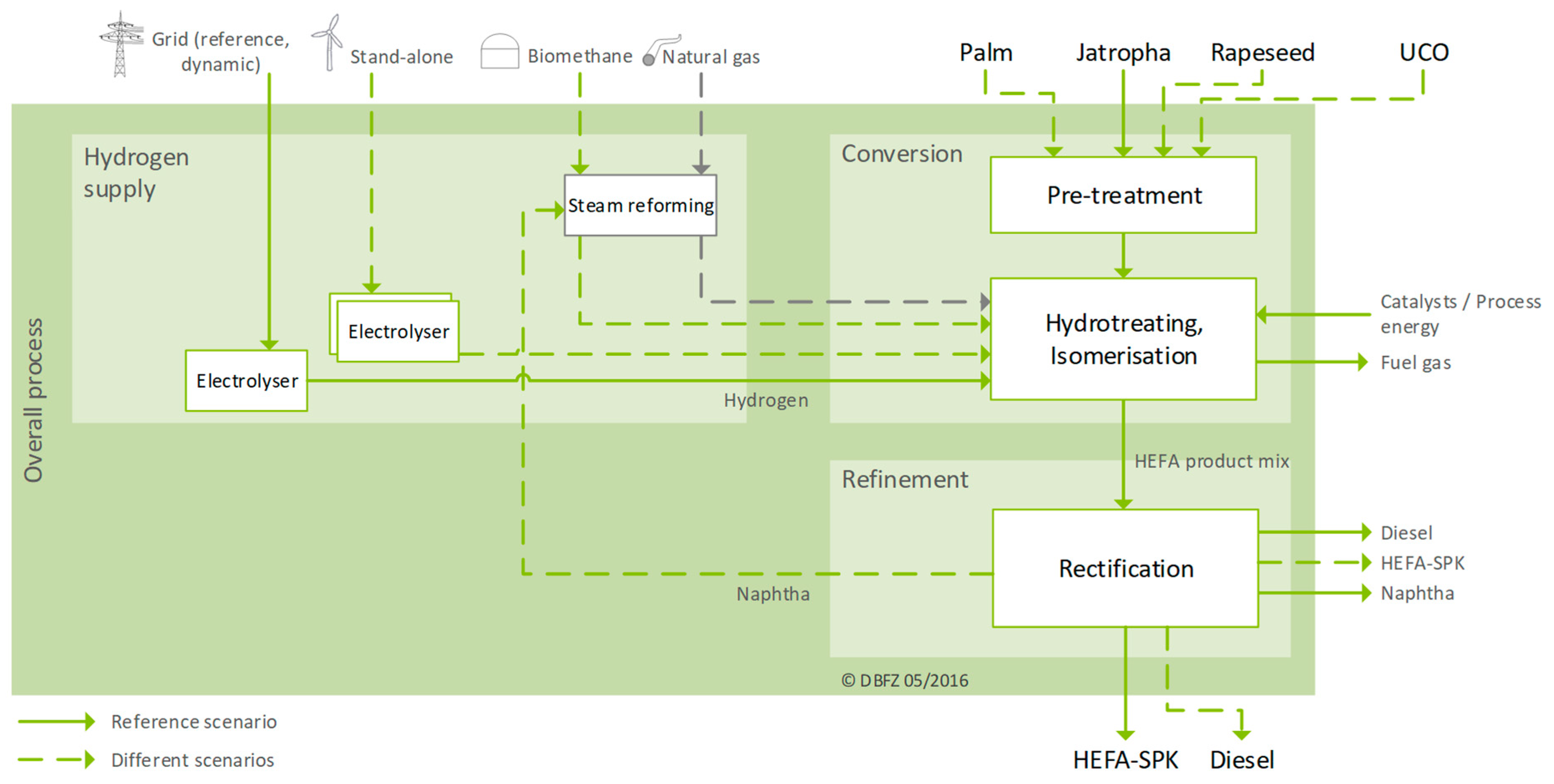
Hydrogen supply: based on alkaline electrolysers with different storage systems depending on the electricity supply and—more conventionally—based on steam reforming from either natural gas, biomethane, or internal use of by-products of the HEFA plant such as naphtha and fuel gases (as is done today in most of the HVO/HEFA plants).
(c)
Feedstocks: as alternatives to jatropha oil; rapeseed oil with regard to the domestic option of, palm oil with regard to cost and specific hydrogen demand, and used cooking oils (UCO) with regard to lower GHG emissions (according the current regulations in the EU) .
(d)
Main product: referring to the different operational modes of a HEFA plant with regard to products, compared to the HEFA-SPK case, the alternative operation mode is focused on producing diesel.

2.2. Technical Assessment

As part of the technical feasibility, the plant conception of the PTG-HEFA hybrid refinery has been elaborated with regard to the different scenarios (Table 1) and—with regard to the assumed startup of such a plant in 2024/25—based on technologies that are and might be available on commercial scale. For all the scenarios, relevant mass and energy flows into and out of the plant have been calculated. Moreover, infrastructural issues with regard to possible locations for such a refinery have been investigated.
As a detailed description of the methods applied for the technical assessment of the PTG part and the HEFA part of the hybrid refinery is presented in [12]. Both parts are described briefly below.

2.2.1. PTG part

The power-to-gas part for the hydrogen supply is realized as alkaline electrolysis of water. The decision to include alkaline electrolysers into the hybrid concept was based on the results of a comprehensive market assessment (including concrete requests for proposal from international electrolyser manufacturers) that shows that only this technology can be provided by 2024/25 in the required capacity (Table 1). The different sizes are based on the calculations made for the different electricity supply scenarios that influence the annual operating hours of the electrolysers. The shorter the equivalent full load period of the electrolyser, the larger the capacity of the electrolyser to cover the hydrogen demand of the HEFA part (121 to 373 MW hydrogen including electricity for hydrogen compression). The hydrogen demand of the HEFA plant amounts to about 17,500 t a−1. At an equivalent full load period of 8000 h a−1, the electrolysis plant has to generate about 2.19 t h−1, leading to an electricity input of 121 MW. At an equivalent full load period of 2600 h a−1, the electrolysis plant has to generate about 6.66 t of hydrogen per hour, leading to an electricity input of 373 MW.
The same is true for the required type and size of the hydrogen storage (short-term underground tube buffer with a volume of 6860 m³ with a net hydrogen storage capacity of 26 t for scenario 1 or salt caverns with a volume of 104,000/213,000 m³ with a net hydrogen storage capacity of 775/1585 t for scenario 2 and 3), and thus the additional electricity demand for storage loading and unloading. The underground tube buffer is based on data from [13]. It has been assumed that for an equivalent full load period of 8000 h a−1 of the electrolysis plant, the required storage capacity amounts to about 0.5 days of full load operation leading to a net hydrogen storage requirement of about 26 t, which is approximately the net storage capacity of the underground tube gas storage described in [13]. Salt caverns only have been applied for scenario 2 and 3, where long-term hydrogen storage is required. Based on data in [14] and the equivalent full load period of the electrolysis plant, the required storage loading compressor capacity (about 2.19 tH2 h−1 for an equivalent full load period of 4000 h yr−1 and about 4.47 tH2 h−1 for an equivalent full load period of 2600 h yr−1) and the required storage volume have been calculated. The hydrogen storage capacity amounts to about 15 days of full load storage loading compressor capacity.

2.2.2. HEFA part

The HEFA as multi-process plant (Figure 2) is derived from [15] and includes a pre-treatment of the feedstock (degumming, bleaching, and neutralisation), two main processing steps (hydrotreating, subsequent hydrocracking, and isomerisation stages), and a product separation (distillation).
All chemical reactions in the HEFA part (especially conversion of triglycerides of the feedstocks into linear, oxygen-free paraffins; saturation of double bonds; and hydrogenation on different paths and cracking) have been analysed on a molecular level according to the exact composition of each feedstock (data from [16,17,18]). This has been done in order to calculate the stoichiometric hydrogen demand per ton of feedstock according to [19,20], and the exact composition of the different fuel products.
The ratio of hydrodeoxygenation and decarboxylation in the conversion of the triglycerides is set to 73%:27% [21,22]. A calculated 30.2% of the CO2 from decarboxylation is subsequently converted into methane by either direct conversion [23] or water–gas–shift reaction and CO methanation [24]. For each feedstock, the cracking rate is set individually depending on the requested product (HEFA-SPK or diesel).
The distribution of fuel products after the cracking stage is based on a normal distribution with a mean of half the initial chain length. The standard deviation is set according to the product distribution described in [25]. The process parameters for both process stages are set in reference to [26], and multiple cracking of one fatty acid is not taken into account.
As a state-of-the-art technology within HEFA facilities, in scenarios 4-6 the hydrogen production via steam reforming is considered instead of the PTG part. In the case of steam reforming, the total electricity demand of the plant is considerably reduced.

2.3. Environmental Assessment

The calculation of the lifecycle GHG emissions for the different scenarios has been conducted by means of a life cycle assessment (LCA), which is standardized and generally defined within DIN ISO 14040 and 14044 standards [27,28]. This general LCA approach described within these standards contains various levels of freedom regarding aspects such as system boundaries, life cycle impact categories, characterization factors, etc., which allow for a dedicated assessment. From a scientific point of view, these degrees of freedom are one of the strengths of LCA, but the results are difficult to compare. Proof of sustainability or, more specifically, evidence of a defined GHG reduction in a certification system requires a simplified method that allows for robust and consistent GHG accounting. For this purpose Annex V of the European Renewable Energy Directive (RED) contains an easy method for the calculation of lifecycle GHG emissions [29]. This method is based on the DIN EN ISO standards but limits the mentioned degrees of freedom by a clear definition of the system boundaries, the consideration of by-products and other aspects, which are described in Table 2.

2.4. Economic Assessment

As part of economic feasibility, specific fuel production costs have been calculated referring to the guideline 6025 of the Association of German Engineers’ (VDI) [33] and by using the dynamic annuity model that takes all relevant cost items into account:
(a)
Capital-linked costs: single and total investments for the different plant designs for the PTG-HEFA hybrid refinery;
(b)
Consumption-linked costs: feedstocks, electricity, and auxiliaries (e.g., water, catalysts, natural gas and biomethane for steam reforming);
(c)
Operation-linked costs: (plant staff, maintenance);
(d)
Other costs: administration, insurance.
Revenues from by-products (here naphtha, fuel gas and diesel) are subtracted from the total costs. These total net-costs divided by the total amount of HEFA-SPK produced (or for scenario 10 for diesel) yield the specific fuel production costs.
A detailed method description for the economic assessment is presented in [12]. The main assumptions can be obtained from Table 3.

2.5. Excursion on Favorable Regions

In addition to the framework analysed for a PTG-HEFA hybrid refinery in Germany, some other favorable regions with regard to high potentials for renewable electricity production have been investigated. Examples for that are Sweden, Spain and Namibia. For these regions, the scenarios 1 and 3 have been analysed with regard to GHG emissions and costs with a special focus on the PTG part of the hybrid refinery. For the stand-alone case with electricity supply from renewables wind power, photovoltaics (pv) and concentrated solar power (csp) have been considered. Details about the specific frame conditions there and the assumptions used for this feasibility analysis can be obtained from [3].

3. Results and Discussion

3.1. Technical Assessment

The results of the mass and energy balances are summarized in Table 4 for the different scenarios. Detailed discussion of these balances can be obtained from [12]. When jatropha is used as feedstock, the specific hydrogen consumption is about 35.7 kg per ton feedstock. For alternative feedstocks, this value is 39.9 kg t−1 for rapeseed; 31.6 kg t−1 for palm; 39.6 kg t−1 for UCO; and, in case of diesel as the main product, about 29.8 kg t−1, with direct impact on the electricity demand for the PTG part (Table 4). The annual demand of potassium hydroxide for the electrolyser is about 940 kg. In case of steam reforming with external supplied natural gas or biomethane, about 67,200 tons per year are required; naphtha and fuel gas for steam reforming are provided plant-internally.
The reference scenario requires an input of 500 kt a−1 jatropha oil. Assuming a yield of established jatropha plantations of 0.5 to 2.2 t ha−1 a−1 [45,46,47], a cultivation area of between 0.227 and 0.833 million ha is necessary, which would constitute a substantial portion of the currently cultivated area of roughly 1 million ha. In order to produce the required 999 GWh a−1 of electricity in the stand-alone scenario using 100% wind and solar power (scenario 3), an appropriate combination would be a wind farm with 360 MW installed power and a solar power park with an area of 625 hectares. In comparison, this is 0.7% of the currently installed wind power in Germany and is substantially larger than the currently largest German solar park of 363 hectares.
In the scenarios with dynamic power procurement and with a stand-alone power production (scenarios 2 and 3), large storage capacities are required (775 t and 1585 t of hydrogen). The most suitable solution is a cavern storage facility in underground salt layers, which can be found in north and central Germany. Since the feedstock will be transported over high seas (except rapeseed and UCO), and with offshore wind farms being more productive, a coastal region close to a large international airport is most suitable for a PTG-HEFA plant of the described dimensions.
Due to its favorable composition, palm oil requires the least hydrogen when being processed into HEFA-SPK. From a purely technical point of view, palm oil would therefore be favorable when hydrogen is being produced by electrolysis. In the scenarios 4–6, where hydrogen production via steam reforming is analysed, the electricity demand is much lower than all other scenarios where the electricity demand derives almost entirely from the energy demand of the electrolysis. Especially in scenario 6, where internally produced naphtha and fuel gas are sufficient for the steam reforming of the required hydrogen, this is a preferable alternative to the reference scenario. Considering the requirements for hydrogen storage and electricity production in the stand-alone scenario, this is especially apparent.

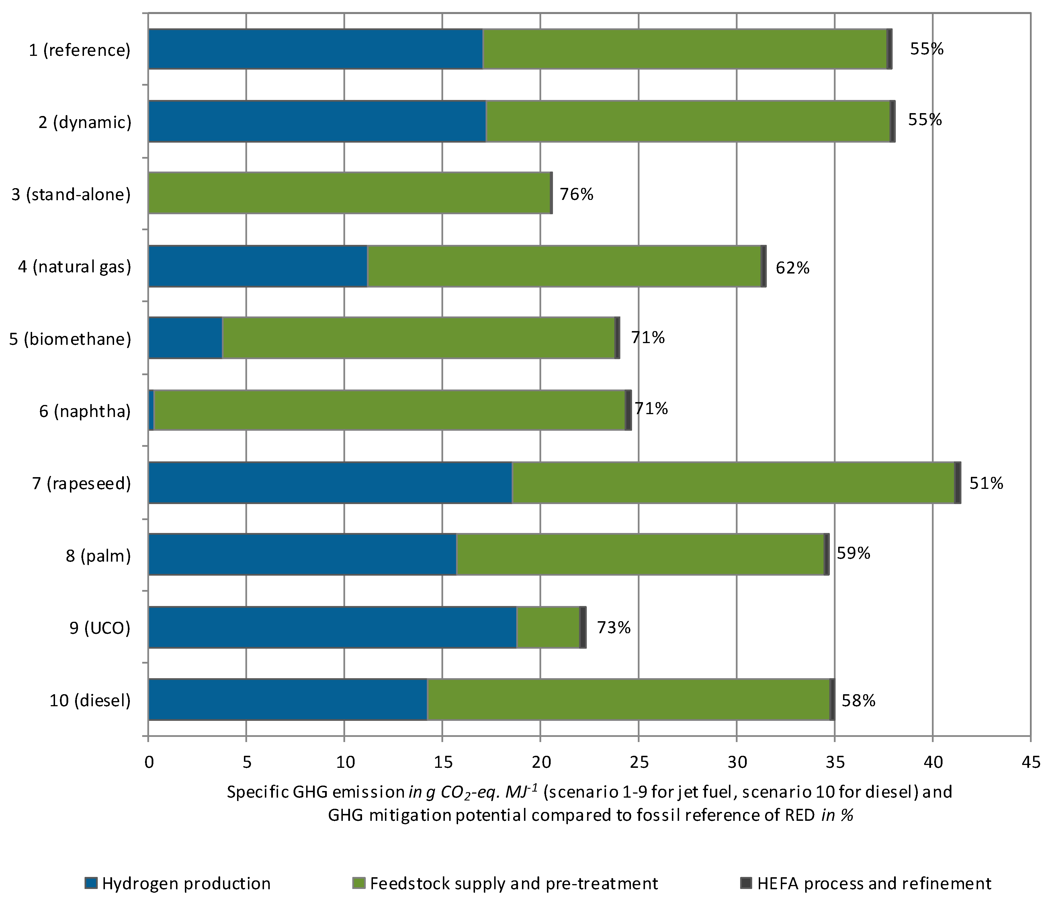
3.2. Environmental Assessment

The GHG balances for the scenarios have been conducted according to the described methodology. Referring to Figure 3, the provision of jatropha-based HEFA-SPK can achieve a GHG reduction of 76% compared to the fossil reference defined in RED. Prerequisite is the exclusive use of electricity from wind and solar systems to cover the process energy demand. The provision of hydrogen via electrolysis is electricity-intensive and the use of grid electricity under the forecasted conditions leads to significantly higher emissions. In particular, the relatively high share of fossil fuels in the German electricity mix prevents higher GHG reductions. Other ways to reduce emissions from the supply of HEFA-SPK, in addition to the use of renewable electricity or a significantly higher share of the same in the electricity mix, is the use of in-process provided naphtha for hydrogen production via steam reforming. Reductions of more than 70% can be achieved here. On the other hand, the use of sustainably grown jatropha, which means jatropha grown mainly from extensive cultivation, can reduce overall GHG emissions.

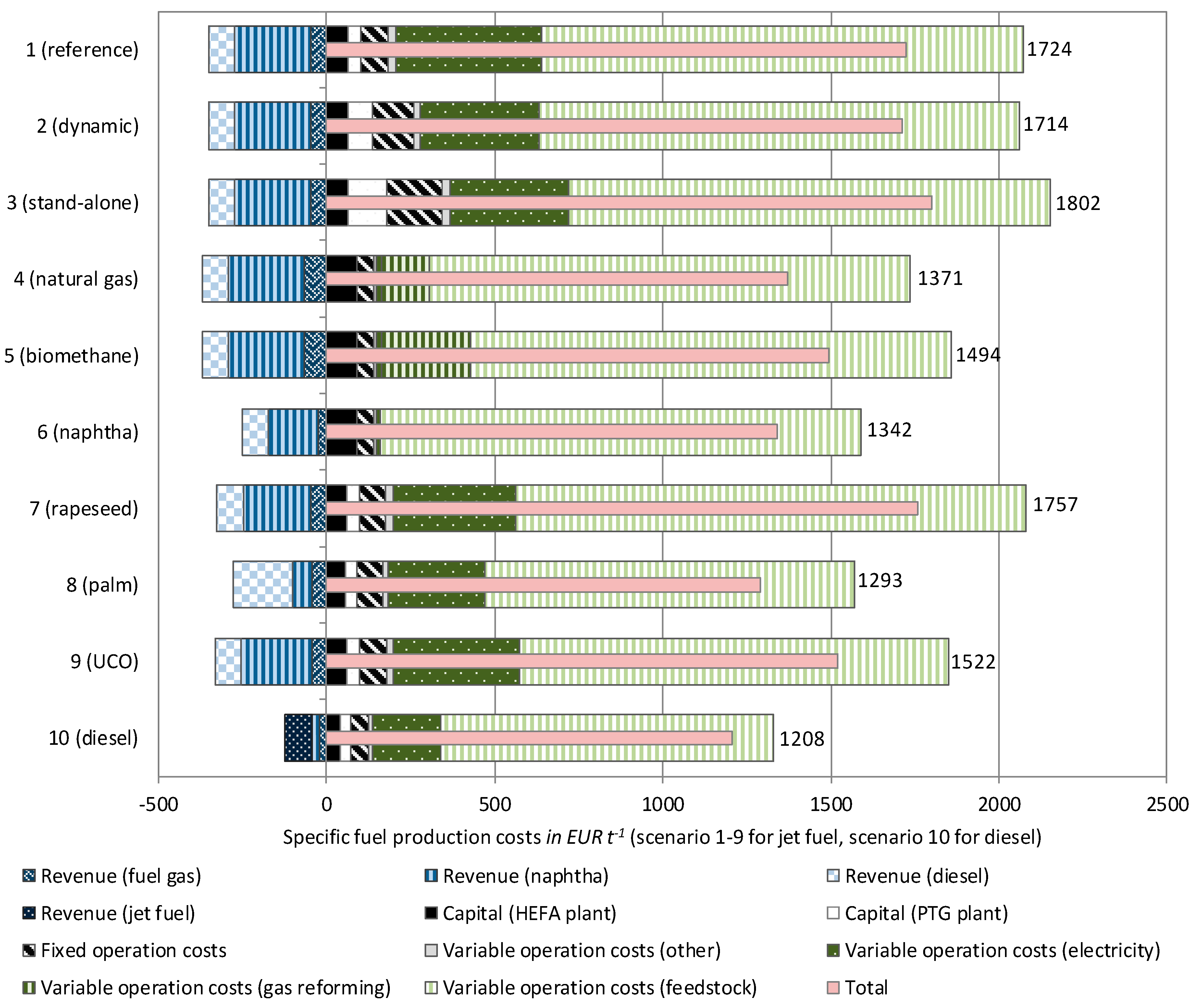
3.3. Economic Assessment

Based on the results of the technical assessment, specific production costs were calculated. Referring to Figure 4, the bandwidth of total production costs is from 1295 to 1800 EUR t−1 for HEFA-SPK, which is well above the current market price of fossil jet fuel of around 425 EUR t−1. Costs can be lowered to 1210 EUR t−1 for shifting the product values to diesel; this is due to the smaller production of short-chained, low-value naphtha and fuel gases.
When analysing the impact of the specific cost components to the total costs, feedstock costs dominate and the contribution from the PTG part is significant. Costs of capital and operation seem negligible in that context. The scenario of steam reforming with naphtha and fuel seems to be more favorable than PTG in terms of costs. This is due to the fact that only small amounts of revenue are lost but large investments in electrolysers and hydrogen storage and therefore also electricity costs are saved.
A more detailed discussion of the results, an exemplarily sensitivity analysis and comparisons with results of similar investigations for HEFA fuels are presented in [12].

3.4. Excursion on Favorable Regions

The results of the GHG and cost calculations are shown in Figure 5, with indication of the minimum GHG mitigation potential according to RED compared to the fossil reference (60% correspond to 33.8 g CO2 eq MJ−1) and the price for fossil jet fuel (about 425 EUR t−1). The most favorable scenarios are the ones with the lowest production costs and at the same time lowest GHG emissions, i.e. with the lowest GHG mitigation costs. According to this, scenario 6 with internal use of naphtha for hydrogen supply might be the most favorable option, followed by scenario 10 if diesel is the main product and scenario 8 if palm oil is used as feedstock. Additionally, the exemplary cases for favorable regions do not show many benefits compared to the German scenarios. Out of them, the reference case in Sweden and the use of wind power for hydrogen production in Spain are the most favorable options.

4. Conclusions

Against the background of a growing aviation sector and the urgent demand on very large amounts of sustainable aviation fuels (SAF), an approach combining existing HEFA technology together with alternative hydrogen supply for processing realized via renewable PTG has been analysed in a comprehensive feasibility study. Ten different scenarios with regard to electricity supply for the PTG part, the hydrogen supply via electrolysis or steam reforming, different feedstocks for the HEFA part, as well as different product mixes were investigated from technical, economic, and environmental points of view.
The technical assessment shows the specific mass and energy balances for the scenario-specific designs of such PTG-HEFA hybrid refineries. They differ, for instance, with regard to hydrogen demand, process energy and related product streams. The least hydrogen is required when processing palm oil to HEFA-SPK (scenario 8) and from a technical point of view it is favorable to generate hydrogen by steam-reforming, as the electrolysis causes the predominant part of the electricity demand of the plant and, in the dynamic and stand-alone scenario (2 and 3), creates technical challenges for storing the hydrogen that can be avoided with constant hydrogen production.
The environmental assessment results allow one to conclude that for all scenarios at least 50% GHG mitigation can be achieved; but following the EU RED with 60% for new plants, just five of 10 concepts achieve that requirement. The use of as much renewable electricity as possible for the PTG part, integrated or other biogenic process energy, and the choice of feedstocks are the most relevant options for high GHG mitigation potentials. Accordingly, all stand-alone scenarios, steam reforming with naphtha from the HEFA plant, or steam reforming with biomethane and the usage of UCO as feedstock are environmentally more favorable.
The economic assessment reveals that the specific fuel production costs highly depend on feedstocks and PTG-related costs. Total production costs are several times higher compared to the current market price of jet fuel. Disregarding scenario 10 where diesel is the main product, the lowest HEFA-SPK production costs are offered, in order, by the scenarios where palm oil is used as feedstock or hydrogen is produced by steam reforming of internal naphtha or natural gas.
Furthermore, the analysis done regarding favorable regions for the PTG part does not show significant benefits of one scenario over the others, as all have very low GHG emissions but are in the upper range of the price spectrum of all examined scenarios. Although producing slightly higher GHG emissions than the stand-alone options, placing the reference scenario in Sweden would result in the most favorable option as the production costs are the lowest when considering different regions.
Taking all investigated scenarios and assessments into account, the lowest GHG mitigation costs arise when internally produced naphtha is used for the hydrogen production by steam reforming (scenario 6). Focussing on diesel as the main product (10) causes just slightly higher GHG mitigation costs but does not offer the required GHG mitigation potential of 60% or more. The next best option in terms of mitigation costs, placing the reference scenario in Sweden, has, compared with the previous two options, the highest GHG mitigation potential at 73%.
The limited HEFA capacities can cover only a small part of the energy demand of the world aviation sector, and all scenarios show higher costs than current kerosene supply does. Although other technologies for renewable sustainable aviation fuels are under R&D&D and new aviation technologies might become relevant in the long-term, the same applies to aviation and all other transport sectors as well: total energy demand needs to be drastically reduced and SAF have to be applied in parallel.

Author Contributions

F.M.-L.: structured and drafted most parts of this article (writing—original draft preparation) based on the results of the above mentioned project which she were the project coordinator and did funding acquisition. K.O.: methodology (environmental assessment), resources, data curation and formal analysis (environmental assessment), writing—review and editing the paper. S.D.: methodology (technical assessment of HEFA part), resources, data curation and formal analysis (technical assessment: calculation of mass and energy balances and definition of infrastructural requirements), writing—review and editing of the paper. K.M.Z.: methodology (economic assessment), resources, data curation and formal analysis (economic assessment), writing, internal review of the paper. M.R.: resources, data curation and formal analysis of electricity supply scenarios in Germany and other countries (esp. demand, capacities, costs), internal review of the paper. W.W.: resources, data curation and formal analysis of technical issues and costs of the PTG plant, internal review of the paper.

Funding

This research was funded by the German Federal Ministry of Transport and Digital Infrastructure (BMVI) and was part of the collaborative project “Feasibility study on a PTG-HEFA hybrid refinery”, investigated from 2015-2017 [3]. The APC was funded by BMVI as well.

Conflicts of Interest

The authors declare no conflict of interest.

Abbreviations

aannum/year
airegAviation Initiative for Renewable Energy in Germany e.V.
app.approximately
ASTMAmerican Society for Testing and Materials
CAPClimate action plan 2050 for Germany
cspconcentrated solar power
EUEuropean Union
GHGgreenhouse gas emissions
GWPglobal warming potential
HEFAhydrotreated esters and fatty acids
IATAInternational Air Transport Association
ktkilo tons (1000 t)
LCALife Cycle Assessment
PJPetajoule
PTGpower-to-gas (here: based on electrolysis to hydrogen)
PTLpower-to-liquid
pvphotovoltaics
REDRenewable Energy Directive
SAFsustainable aviation fuels
SPKsynthetic paraffinic kerosine
SynBioPTxsynergies (syn) of biomass-based (bio) and electricity-based (PTx) fuels and product processes
UCOused cooking oil
VDIVerein Deutscher Ingenieure (Association of German Engineers’)

References

  1. EASA. European Aviation Environmental Report 2019; EASA, EEA, Eurocontrol: Brussels, Belgium, 2019. [Google Scholar] [CrossRef]
  2. Le Feuvre, P. Commentary: Are Aviation Biofuels Ready for Take Off? Available online: https://www.iea.org/newsroom/news/2019/march/are-aviation-biofuels-ready-for-take-off.html (accessed on 22 March 2019).
  3. Dietrich, S.; Oehmichen, K.; Zech, K.; Müller-Langer, F.; Majer, S.; Kalcher, J.; Naumann, K.; Wirkner, R.; Pujan, R.; Braune, M.; et al. Studie im Rahmen der Mobilitäts-und Kraftstoffstrategie der Bundesregierung (MKS) im Auftrag für das Bundesministerium für Verkehr und digitale Infrastruktur (BMVI). In Machbarkeitsanalyse für eine PTG-HEFA Hybridraffinerie in Deutschland; Deutsches Biomasseforschungszentrum gemeinnützige GmbH (DBFZ): Leipzig, Germany, 2017. [Google Scholar]
  4. Naumann, K.; Schröder, J.; Oehmichen, K.; Etzold, H.; Müller-Langer, F.; Remmele, E.; Thuneke, K.; Raksha, T.; Schmidt, P. Monitoring Biokraftstoffsektor, 4th ed.; Deutsches Biomasseforschungszentrum Gemeinnützige GmbH (DBFZ): Leipzig, Germany, 2019; ISBN 978-3-946629-36-8. [Google Scholar]
  5. Müller-Langer, F.; Dietrich, R.U.; Krol, R.V.D.; Arnold, K.; Harnisch, F.; Erneuerbare Kraftstoffe für Mobilität und Industrie. FVEE Themen 2016—Netze und Speicher für die Energiewende—Erneuerbare Kraftstoffe. 2016. Available online: http://www.fvee.de/fileadmin/publikationen/Themenhefte/th2016/th2016_07_05.pdf (accessed on 13 September 2019).
  6. Müller-Langer, F.; Etzold, H.; Naumann, K. BTx and PTx as competitors or companions: A systemic assessment. In Proceedings of the 8th ETIP Stakeholder Plenary Meeting, Brussels, Belgium, 11–12 April 2018; Available online: http://www.etipbioenergy.eu/images/SPM8_Presentations/ETIP_Mueller-Langer_2018-04_new.pdf (accessed on 13 September 2019).
  7. Schmidt, P.; Weindorf, W.; Roth, A.; Batteiger, V.; Riegel, F. Power-to-Liquids—Potentials and Perspectives for the Future Supply of Renewable Aviation Fuel; German Environment Agency: Dessau-Roßlau, Germany, 2016; Available online: https://www.umweltbundesamt.de/sites/default/files/medien/377/publikationen/161005_uba_hintergrund_ptl_barrierrefrei.pdf (accessed on 13 September 2019).
  8. Schmidt, P.; Weindorf, W.; Zittel, W. Renewables in Transport 2050—Empowering a Sustainable Mobility Future with Zero Emission Fuels from Renewable Electricity—Europe and Germany. In Report 1086–2016; Forschungsvereinigung Verbrennungskraftmaschinen e.V.: Frankfurt am Main, Germany, 2015; Available online: http://www.lbst.de/news/2016_docs/FVV_H1086_Renewables-in-Transport-2050-Kraftstoffstudie_II.pdf (accessed on 13 September 2019).
  9. Schmied, M.; Wüthrich, P.; Zah, R.; Althaus, H.J.; Friedl, C. Postfossile Energieversorgungsoptionen für einen treibhausgasneutralen Verkehr im Jahr 2050: Eine verkehrsträgerübergreifende Bewertung. In TEXTE 30/2015—Umweltforschungsplan des Bundesministeriums für Umwelt, Naturschutz, Bau und Reaktorsicherheit; German Environment Agency: Dessau-Roßlau, Germany, 2015; Available online: https://www.umweltbundesamt.de/sites/default/files/medien/378/publikationen/texte_30_2015_postfossile_energieversorgungsoptionen.pdf (accessed on 13 September 2019).
  10. Albrecht, F.G.; Dietrich, R.-U. Alternative fuels from Biomass and Power (PBtL) A case study on process options, technical potentials, fuel costs and ecological performance. In Proceedings of the European Biomass Conference, Stockholm, Sweden, 12–15 July 2017; Available online: https://elib.dlr.de/115071/ (accessed on 13 September 2019).
  11. Müller-Langer, F.; Vogel, A.; Brauner, S. Renwew—Renewable fuels for advanced powertrains—Deliverable 5.3.8. Overall Costs; Institute for Energy and Environment: Leipzig, Germany, 2008; Available online: http://www.renew-fuel.com/download.php?dl=del_sp5_wp3_5-3-8_08-02-27_iee-draft.pdf&kat=18 (accessed on 13 September 2019).
  12. Zech, K.M.; Dietrich, S.; Reichmuth, M.; Weindorf, W.; Müller-Langer, F. Techno-economic assessment of a renewable bio-jet-fuel production using power-to-gas. Appl. Energy 2018, 231, 997–1006. [Google Scholar] [CrossRef]
  13. Jauslin Stebler, A.G. Erdgas-Röhrenspeicher Urdorf. Available online: https://www.jauslinstebler.ch/VGA/VEM/projekte/erdgas-roehrenspeicher-urdorf.html (accessed on 23 July 2018).
  14. Doradei, S.; Crotogino, F.; Acht, A.; Horvarth, P.-L. Speicherung von Wasserstoff in Salzkavernen. In Integration von Wind-Wasserstoff-Systemen in das Energiesystem; Nationales Innovationsprogramm Wasserstoff-und Brennstoffzellentechnologie (NIP): Berlin, Germany, 2013. [Google Scholar]
  15. Gröngröft, A.; Meisel, K.; Hauschild, S.; Grasemann, E.; Peetz, D.; Mayer, K.; Teil, I.I. Wissenschaftliche Untersuchung von Wegen der Biokerosinproduktion aus verschiedenen Biomassetypen. In Abschlussbericht zu dem Vorhaben Projekt BurnFAIR; Zschocke, A., Ed.; Deutsche Lufthansa: Frankfurt am Main, Germany, 2014. [Google Scholar]
  16. Liu, Y.; Sotelo-Boyás, R.; Murata, K.; Minowa, T.; Sakanishi, K. Hydrotreatment of vegetable oils to produce bio-hydrogenated diesel and liquefied petroleum gas fuel over catalysts containing sulfided Ni–Mo and solid acids. Energy Fuels 2011, 25, 4675–4685. [Google Scholar] [CrossRef]
  17. Dubois, V.; Breton, S.; Linder, M.; Fanni, J.; Parmentier, M. Fatty acid profiles of 80 vegetable oils with regard to their nutritional potential. Eur. J. Lipid Sci. Technol. 2007, 109, 710–732. [Google Scholar] [CrossRef]
  18. Abidin, S.Z.; Patel, D.; Saha, B. Quantitative analysis of fatty acids composition in the used cooking oil (UCO) by gas chromatography−mass spectrometry (GC-MS). Can. J. Chem. Eng. 2013, 91, 1896–1903. [Google Scholar] [CrossRef]
  19. Majer, S.; Hauschild, S.; Müller-Langer, F. Kurzstudie im Auftrag des Verbandes der Deutschen Biokraftstoffindustrie e.V., der Union zur Förderung von Öl-und Proteinpflanzen e.V. und des OVID Verband der ölsaatenverarbeitenden Industrie in Deutschland e.V. In Energie-und Treibhausgasbilanz von HVO-Kraftstoff. Eine vergleichende Analyse; Deutsches Biomasseforschungszentrum gemeinnützige GmbH (DBFZ): Leipzig, Germany, 2014. [Google Scholar]
  20. Endisch, M.; Balfanz, U.; Olschar, M.; Kuchling, T. Vegetable Oil Hydrotreating for Production of High Quality Diesel Components. In Proceedings of the DGMK Future Feedstocks for Fuels and Chemicals Conference, Berlin, Germany, 29 September–1 October 2008. [Google Scholar]
  21. Nikander, S. Greenhouse Gas and Energy Intensity of Product Chain: Case Transport Bio-fuel. Master’s Thesis, Helsinki University of Technology, Helsinki, Finland, 9 May 2008. [Google Scholar]
  22. Smejkal, Q.; Smejkalová, L.; Kubička, D. Thermodynamic balance in reaction system of total vegetable oil hydrogenation. Chem. Eng. J. 2008. [Google Scholar] [CrossRef]
  23. Jęczmionek, Ł.; Porzycka-Semczuk, K. Hydrodeoxygenation, decarboxylation and decarbonylation reactions while co-processing vegetable oils over NiMo hydrotreatment catalyst. Part II. Thermal effects—Experimental results. Fuel 2014, 128, 296–301. [Google Scholar] [CrossRef]
  24. Hiller, H.; Reimert, R.; Stönner, H.-M. Gas Production. 1. Introduction. In Ullmann’s Encyclopedia of Industrial Chemistry; Wiley-VCH: Weinheim, Germany, 2014. [Google Scholar] [CrossRef]
  25. Kinder, J.D.; Rahmes, T. Evaluation of Bio-Derived Synthetic Paraffinic Kerosene (Bio-SPK). 2009. Available online: http://www.safug.org/assets/docs/biofuel-testing-summary.pdf (accessed on 15 August 2019).
  26. Myllyoja, J.; Aalto, P.; Savolainen, P.; Purola, V.-M.; Alopaeus, V.; Grönqvist, J. Process for the Manufacture of Diesel Range Hydrocarbons. U.S. Patent US8022258 B2, 20 September 2011. [Google Scholar]
  27. German Institute for Standardisation. Environmental Management—Life Cycle Assessment—Principles and Framework; DIN ISO 14040: Geneva, Switzerland, 2006. [Google Scholar]
  28. German Institute for Standardisation. Environmental Management—Life Cycle Assessment—Requirements and Guidelines; DIN ISO 14044: Geneva, Switzerland, 2006. [Google Scholar]
  29. European Commission. Directive 2009/28/EC of the European Parliament and of the Council of 23 April 2009 on the promotion of the use of energy from renewable sources and amending and subsequently repealing Directives 2001/77/EC and 2003/30/EC. Off. J. Eur. Union 2009. Available online: http://www.nezeh.eu/assets/media/fckuploads/file/Legislation/RED_23April2009.pdf (accessed on 27 September 2019).
  30. Ecoinvent Center. Ecoinvent Version 3 Life Cycle Inventory Database; Swiss Center for Life Cycle Inventories: St. Gallen, Switzerland, 2016; database. [Google Scholar]
  31. IINAS GmbH. GEMIS—Global Emissions Model for integrated Systems V4.94. Version: International Institute for Sustainability Analysis and Strategy GmbH. Database. Available online: http://www.gemis.de (accessed on 26 September 2019).
  32. Solomon, S.; Quin, D.; Manning, M.; Chen, Z.; Marquis, M.; Averyt, K.B. Climate Change 2007: The Physical Science Basis. Contribution of Working Group I to the Fourth Assessment Report of the Intergovernmental Panel on Climate Change; Cambridge University Press, IPCC: Cambridge, UK; New York, NY, USA, 2007. [Google Scholar]
  33. The Association of German Engineers (VDI). Guideline 6025—Economy Calculation Systems for Capital Goods and Plants; Beuth-Verlag GmbH: Berlin, Germany, 2012. [Google Scholar]
  34. National Renewable Energy Laboratories (NREL). Task 1: Cost estimates of small modular systems. In Equipment Design and Cost Estimation for Small Modular Biomass Systems, Synthesis Gas Cleanup, and Oxygen Separation Equipment; NREL/SR-510-39943; National Renewable Energy Laboratories (NREL): Golden, CO, USA, 2006. [Google Scholar]
  35. Davis, R.; Kinchin, C.; Markham, J.; Tan, E.; Laurens, L.; Sexton, D.; Knorr, D.; Schoen, P.; Lukas, J. Process Design and Economics for the Conversion of Algal Biomass to Biofuels: Algal Biomass Fractionation to Lipid and Carbohydrate-Derived Fuel Products; NREL/TP-5100-62368; National Renewable Energy Laboratories (NREL): Golden, CO, USA, 2014. Available online: https://www.nrel.gov/docs/fy14osti/62368.pdf (accessed on 3 September 2019).
  36. Eurostat. Harmonized index for consumer prices; industrial goods; Table: [prc_hicp_aind]; 2016. Available online: http://appsso.eurostat.ec.europa.eu/nui/show.do?dataset=prc_hicp_aind&lang=de (accessed on 25 September 2019).
  37. Eurostat. Euro/Ecu exchange rates; Table: [ert_bil_eur_a]; 2018. Available online: http://appsso.eurostat.ec.europa.eu/nui/show.do?dataset=ert_bil_eur_a&lang=en (accessed on 25 September 2019).
  38. Deutsches Zentrum für Luft-und Raumfahrt (DLR); Ludwig-Bölkow-Systemtechnik (LBST); Fraunhofer ISE; KBB Underground Technologies. Studie über die Planung einer Demonstrationsanlage zur Wasserstoff-Kraftstoffgewinnung durch Elektrolyse mit Zwischenspeicherung in Salzkavernen unter Druck. Stuttgart, Germany, 2015. Available online: http://www.lbst.de/ressources/docs2015/BMBF_0325501_PlanDelyKaD-Studie.pdf (accessed on 23 July 2018).
  39. Nationales Innovationsprogramm Wasserstoff-und Brennstoffzellentechnologie (NIP). Integration von Wind-Wasserstoff-Systemen in das Energiesystem, Berlin, 2013. Available online: https://www.now-gmbh.de/content/1-aktuelles/1-presse/20140402-abschlussbericht-zur-integration-von-wind-wasserstoff-systemen-in-das-energiesystem-ist-veroeffentlicht/abschlussbericht_integration_von_wind-wasserstoff-systemen_in_das_energiesystem.pdf (accessed on 18 July 2018).
  40. Braune, M.; Grasemann, E.; Gröngröft, A.; Klemm, M.; Oehmichen, K.; Zech, K. Die Biokraftstoffproduktion in Deutschland—Stand der Technik und Optimierungsansätze, 1st ed.; DBFZ report no. 22; Deutsches Biomasseforschungszentrum gemeinnützige GmbH (DBFZ): Leipzig, Germany, 2016; ISBN 978-3-9817707-8-0. [Google Scholar]
  41. Turton, R.; Shaeiwitz, J.A.; Bhattacharyya, D.; Whiting, W.B. Analysis, Synthesis and Design of Chemical Processes, 5th ed.; Pearson Education; Prentice Hall International Series in the Physical and Chemical Engineering Sciences: Boston, MA, USA, 2018. [Google Scholar]
  42. Aviation Initiative for Renewable Energy in Germany e. V. (aireg). Database on Jatropha. 2015; unpublished. [Google Scholar]
  43. Adler, P.; Billig, E.; Brosowski, A.; Daniel-Gromke, J.; Falke, I.; Fischer, E.; Grope, J.; Holzhammer, U.; Postel, J.; Schnutenhaus, J.; et al. (Eds.) Leitfaden Biogasaufbereitung und-einspeisung; Fachagentur Nachwachsende Rohstoffe e.V.: Gülzow, Germany, 2014; ISBN 3-00-018346-9. [Google Scholar]
  44. Oil Price Information Service (OPIS). Europe Jet, Diesel and Gasoil Report; Oil Price Information Service (OPIS): Rockville, MD, USA, 2016. [Google Scholar]
  45. Kumar, S.; Singh, J.; Nanoti, S.M.; Garg, M.O. A comprehensive life cycle assessment (LCA) of Jatropha biodiesel production in India. Bioresour. Technol. 2012, 110, 723–729. [Google Scholar] [CrossRef] [PubMed]
  46. Eshton, B.; Katima, J.H.Y.; Kituyi, E. Greenhouse gas emissions and energy balances of jatropha biodiesel as an alternative fuel in Tanzania. Biomass Bioenergy. 2013, 58, 95–103. [Google Scholar] [CrossRef]
  47. Dehue, B.; Hettinga, W. GHG Performance Jatropha Biodiesel. Commissioned by D1 oils, Ref no. PBIONL073010. Ecofys Reference 2. 2008. Available online: https://pdfs.semanticscholar.org/2f0b/c772fedd5e7988593084bd4113c1a5c78472.pdf (accessed on 26 September 2019).
Figure 1. Jet fuel demand of all flights departing in Germany, emissions to be reduced, and the share of required renewable jet fuels to fulfill targets like of aireg, IATA, and climate protection plan (adapted from [3]).
Applsci 09 04047 g001
Figure 2. Simplified scheme of PTG-HEFA hybrid refinery and scope.
Applsci 09 04047 g002
Figure 3. Specific GHG emission per scenario for HEFA-SPK and HEFA-diesel, and GHG mitigation potential compared to fossil reference of the European Renewable Energy Directive (RED).
Applsci 09 04047 g003
Figure 4. Specific fuel production costs per scenario.
Applsci 09 04047 g004
Figure 5. Comparison of production costs and GHG emissions for different scenarios and exemplary favorable regions.
Applsci 09 04047 g005
Table 1. Scenarios and their specific assumptions.
ScenarioFeedstockElectricity SupplyNecessary Hydrogen Supply (Electricity Demand in MW) 1Main Product
1 (reference)jatropha oilConstant from grid (with electricity mix): 8000 h a−1121 MW alkaline electrolyser incl. tube buffer storageHEFA-SPK
2 (dynamic)Dynamic from grid (spot market prices): 4000 h a−1244 MW alkaline electrolyser incl. salt cavern storage
3 (stand-alone)Stand-alone system (wind 360 MW and solar 250 MW): 2600 h a−1373 MW alkaline electrolyser with operated in varying part loads incl. salt cavern storage
4 (natural gas)Constant from grid (with electricity mix): 8000 h a−1via steam reforming from natural gas
5 (biomethane)via steam reforming from biomethane
6 (naphtha)via steam reforming from naphtha and fuel gas
7 (rapeseed)rapeseed oil 121 MW alkaline electrolyser incl. tube buffer storage
8 (palm)palm oil
9 (UCO)used cooking oil
10 (diesel)jatropha oildiesel
1 cf. calculations in Section 2.2.1
Table 2. Methodology and assumptions for life cycle assessment (LCA).
Methodology StepAssumptions for PTG–HEFA Hybrid Refinery
Goal and scope definition
 Considered impact categoriesGlobal warming potential (GWP)
 Functional unit1 MJ fuel ex hybrid refinery
 System boundary for LCAWell-to-tank-chain including feedstock production (w/o direct or indirect land use changes), biomass collection of UCO and fuel production.
No consideration of infrastructure (i.e., built up of plants, components, and vehicles)
 Consideration of by-productsAccording to European Renewable Energy Directive (2008/29/EC) allocation of by-products (here, the subdivision of emissions and demands along the production chain between HEFA-SPK and naphtha, fuel gas, and diesel) and according to their energy content (lower heating value)
Inventory calculation
 Input/output analysisConsideration of all relevant input and output streams (i.e., energy and feedstock inputs, auxiliaries and utilities, products and by-products, and waste) within the system boundary
Concepts based on process simulation, own data, and EcoInvent Version 3.3 [30]
External electrical power based on country specific mixes for 2015, emissions according to Gemis [31]
Impact assessment
 ApproachEvaluation of data resulting from input/output analysis regarding potential environmental impacts by means of so called characterising factor aggregation with regard to one reference substance
 GHG emissionsAccording Forth IPCC Assessment Report (AR4)
CH4 with 25 CO2-eq, N2O with 298 CO2-eq
(w/o consideration of process-related biogenous CO2 emissions) [32]
Result interpretation
cf. Section 3.2
Table 3. Main assumptions for fuel production cost calculation (reference year 2015, assessment period 30 years).
Cost FactorValue/AssumptionReference
Total investment
 HEFA process units/incl. steam reformer132/190 million EUR (annual load 8000 h)[34,35,36,37]
 electrolyser58 million EUR (annual load 8000 h)
116 million EUR (annual load 4000 h)
176 million EUR (annual load 2600 h)
[38], quotations and interviews
 hydrogen compression and storage24 million EUR (annual load 8000 h)
38 million EUR (annual load 4000 h)
70 million EUR (annual load 2600 h)
[13,39]
Costs
 weighted average cost of capital8% per year[40]
 maintenance HEFA part2.5% of total investment per year[34,35]
 maintenance PTG part9% of total investment per year[38], quotations and interviews
 administration, insurance, other2.5% of total investment per year[40]
 personnel staff50,000 EUR per year and person with full-time equivalent; app. 50 full-time equivalents required[40,41,35]
 feedstock (jatropha, rapeseed, palm, and UCO)650/720/547/600 EUR t−1[4,42]
 electricity (reference, dynamic, and stand-alone)100/80/80 EUR MWh−1[12]
 auxiliaries steam reformer (natural gas, biomethane)480/896 EUR t−1[43] (biomethane)
 ..other auxiliaries (water, potassium hydroxide)2/820 EUR t−1[40]
Revenues
 ..naphtha, fuel gas380/400 EUR t−1[44]
 ..diesel, jet fuel410/425 EUR t−1[44]
Table 4. Most important mass and energy balances for the different scenarios.
ScenarioInputs Outputs
Feedstock aElectricity bWater aHEFA-SPK aDiesel aNaphtha aFuel Gas a
1 (reference)5009882222274013526.4
2 (dynamic)5009962222274013526.4
3 (stand-alone)5009992222274013526.4
4 (natural gas)500332542274013536.2
5 (biomethane)500332542274013536.2
6 (naphtha)50032279227408813.7
7 (rapeseed)50010882402374512327.1
8 (palm)5008842032491043825.1
9 (UCO)50010962412354312924.7
10 (diesel)500826192603282214.7
a kt a−1; b GWh a−1.

