Article

Shipborne Acquisition, Tracking, and Pointing Experimental Verifications towards Satellite-to-Sea Laser Communication

1
Institute of Optics and Electronics, Chinese Academy of Sciences, No.1 Guangdian Road, Chengdu 610209, China
2
Key Laboratory of Optical Engineering, Chinese Academy of Sciences, Chengdu 610209, China
3
University of Chinese Academy of Sciences, Beijing 100049, China
4
Department of Modern Physics and Hefei National Laboratory for Physical Sciences at the Microscale, University of Science and Technology of China, Hefei 230026, China
5
Chinese Academy of Sciences (CAS) Center for Excellence and Synergetic Innovation Center in Quantum Information and Quantum Physics, University of Science and Technology of China, Shanghai 201315, China
*
Author to whom correspondence should be addressed.
Appl. Sci. 2019, 9(18), 3940; https://doi.org/10.3390/app9183940
Submission received: 1 August 2019 / Revised: 12 September 2019 / Accepted: 16 September 2019 / Published: 19 September 2019

Abstract

:
Acquisition, tracking, and pointing (ATP) is a key technology in free space laser communication that has a characteristically high precision. In this paper, we report the acquisition and tracking of low-Earth-orbit satellites using shipborne ATP and verify the feasibility of establishing optical links between laser communication satellites and ships in the future. In particular, we developed a shipborne ATP system for satellite-to-sea applications in laser communications. We also designed an acquisition strategy for satellite-to-sea laser communication. In addition, a method was proposed for improving shipborne ATP pointing error. We tracked some stars at sea, achieving a pointing accuracy of less than 180μrad.We then acquired and tracked some low-Earth-orbit satellites at sea, achieving a tracking accuracy of about 20μrad. The results achieved in this work experimentally demonstrate the feasibility of ATP in satellite-to-sea laser communications.

1. Introduction

Laser communication is a technology that uses a laser beam as a carrier to transmit information in space [1,2]. The laser beam used in space laser communication is emitted at an angle that is near the diffraction limit. The divergence angle of very narrow communication beams requires both communicating sides to maintain extremely high dynamic alignment accuracy. With the ultimate aim of realizing a global-scale laser communication for practical use, many significant achievements have been made in the past decades, such as the demonstration of links for building-to-building communication [3,4], airborne applications [5,6,7], inter-satellite applications [8,9], satellite-to-ground [10,11,12,13,14,15,16], and ship-to-ship communication [17,18,19]. However, currently, most of the experiments only involve space and ground communication links or short-distance communication between ships. Since water bodies occupy more than 70% of the earth’s surface and given the rising demand for maritime communications, the global-scale communication network is bound to extend from the ground to the sea in the future. Huge volumes of data need to be transmitted by satellite. Thus, there is an urgent need to conduct experimental verifications of laser communication between satellites and ships at sea.
Satellite-to-sea laser communication mainly refers to data transmission between satellites and shipboards. Acquisition, tracking, and pointing (ATP) is the key technology used in laser communication, which requires the rapid acquisition and alignment of line-of-sight between two platforms and the establishment of communication links with high precision, high probability, and high dynamic tracking. The ATP system’s rapid and high probability acquisition of a satellite terminal’s line-of-sight under shipborne conditions has a direct impact on the communication time. Currently, optical links between ships have been verified. The link is usually initiated actively by an ATP at one end to cover an uncertain area with beacon light, then scanned or stared at by an ATP at another end to establish the link. This method of establishing an optical link is the most common method in laser communication, which requires high pointing accuracy. For short-distance communication links of tens of kilometers between ships or in air [20,21], the divergence angle and optical power of the beacon light can be improved, and the requirement of the ATP with respect to the pointing accuracy can be reduced to reduce the difficulty of acquisition. Another method for realizing short-range ship-to-ship laser communication is using modulating retro-reflectors (MRRs). An MRR link uses an active ATP at one end and a small semi-passive MRR at the other [22,23,24,25]. For one end of the link, MRRs no longer have tight pointing requirements. However, satellite-to-sea laser communication is very different from ground ATP systems. For ship-to-ship laser communications of tens of kilometers, the divergence angle of the uplink beacon is usually only a few milliradians due to resource constraints. The MMR method is less likely to achieve communication over hundreds or thousands of kilometers of links. Moreover, the complex nature of the ocean environment significantly increases the difficulty of acquisition and tracking by the ATP system. It is difficult for shipborne ATP systems to achieve high pointing accuracy to complete initial acquisition under conditions such as random and sharp waggling along with the sea, which poses a higher challenge to its technology. As a first step toward satellite-to-sea laser communication, it is essential to develop shipborne ATP and test its performance.
In this paper, we report the acquisition and tracking of low-Earth-orbit satellites using shipborne ATP and verify the establishment of optical links between laser communication satellites and a ship at sea. To improve the initial pointing accuracy of line-of-sight in the satellite-to-sea laser communication, we designed a calibration method for the shipborne ATP pointing error model. Some satellites were acquired and tracked by the ATP system, thereby demonstrating the acquisition and tracking performance of the ATP system at sea. A tracking accuracy of about 20μrad was obtained, together with a pointing accuracy of less than 180μrad.Our implementation provides a solid test for shipborne ATP, thus paving the way for a global-scale laser communication network involving space, ground, and sea.

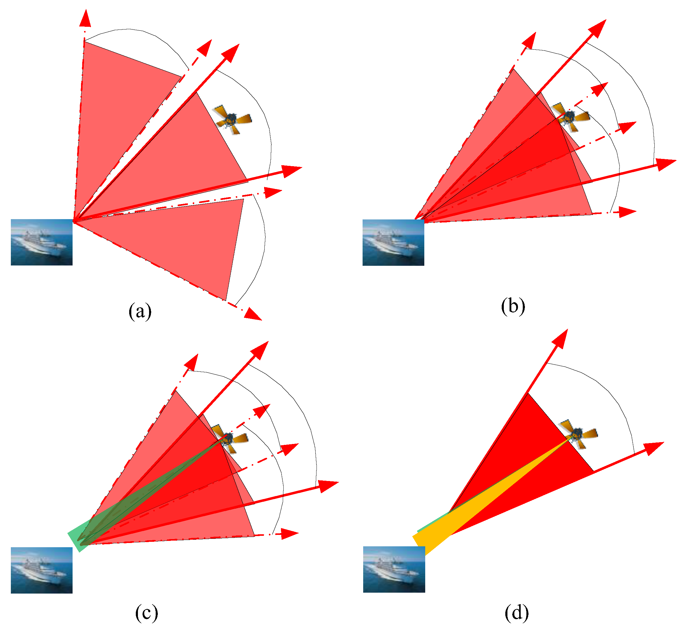
2. Strategies for Establishing Optical Links

We designed an acquisition process for satellite-to-sea laser communication. The communication handshake is initiated by shipborne ATP. The terminals on each side of the communication drive their respective optical antennas to roughly align with each other’s instantaneous positions according to the ephemeris and attitude information. Shipborne ATP has high-precision pointing ability and can transmit uplink beacon light to accurately cover the satellite terminal. After the satellite coarse Charge Coupled Device (CCD) detects the beacon light of the shipborne ATP, closed-loop tracking is carried out with high accuracy. The satellite terminal emits downlink beacon light. After the downlink beacon light is detected by the shipboard ATP coarse CCD, stable closed-loop tracking is conducted to complete the acquisition. After establishing a stable communication link between the satellite and the sea, laser communication is achieved until the satellite passes through. The acquisition strategy is summarized in Figure 1.

3. Method for Improving the Pointing Error

The acquisition protocol involves the shipborne ATP irradiating the satellite to initiate a link. The ATP is fixed on the ship. As the ship moves, the ATP is affected by sea waves, thus producing three periodic yaw, pitch, and roll disturbances, which cause the ATP’s line-of-sight axis to wobble a few degrees. The divergence angle of the uplink beacon laser cannot be increased indefinitely; it is generally several milliradians and much smaller than the swaying amplitude. To achieve the acquisition of a satellite, the acquisition performance can only be improved by reducing the pointing error. The absolute pointing error is defined as the angular separation between the actual direction and the intended ATP line-of-sight [26]. In invisible satellite target acquisition, the pointing accuracy of the telescope is one of the important indices for the establishment of optical links. In our experiment, several factors contribute to the pointing error, including the attitude of the ship platform pre-compensation accuracy, installation error calibration accuracy, and systematic errors calibration accuracy.

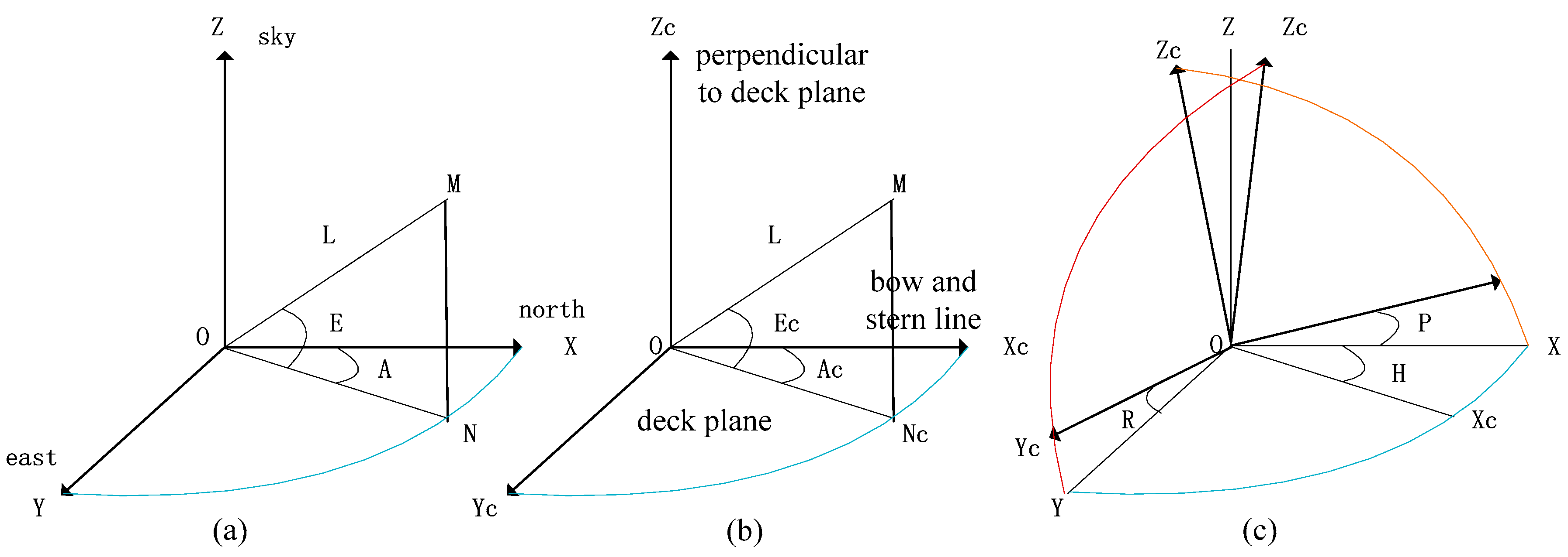
3.1. Pre-compensation for Ship Platform Attitude

During the initial acquisition stage, the target coordinate value (A, E) in the Northeast celestial coordinate system is converted to ( A c , E c ) in the deck coordinate system. ( A c , E c ) is used to guide the ATP to open-loop pointing.
As shown in Figure 2a, the Northeast celestial coordinate system is defined as O-XYZ, where OX is due North, OY is due east, and OZ is due sky. The origin, O is the intersection of the azimuth axis and the pitching axis of the tracking equipment. The polar coordinates of the observation point, M are (A, E), while the projection of M on the OXY plane is N. A represents the azimuth angle, that is, the included angle of XON, which is positive when overlooking clockwise. E represents the elevation angle, which is the angle MON, where up is positive. L represents the distance from the tracking device to the observation point.
As shown in Figure 2b, the deck coordinate system O - X c Y c Z c is defined; the axis X c is the fore-and-aft line, while the bow direction is forward. The axis OZ c is positive clock wise; the axis Y c is perpendicular to the fore-and-aft line in the deck plane, whereas the axis OZ c is perpendicular to the deck plane, upward is positive. The origin O is consistent with the Northeast celestial coordinate system. The projection point of M on plane OX c Y c is N c . The polar coordinates of M in the deck coordinate system are defined as ( A c , E c ) . A c represents the azimuth angle of the deck, where clockwise is positive. E c represents the elevation angle of the deck; upward is positive.
As shown in Figure 2c, the roll angle, R is the angle obtained by rotating the fore-and-aft line of the deck platform, and the port side rising is defined as a positive angle. The pitch angle, P is the angle included between the fore-and-aft line and the horizontal plane, and P is the positive angle when the bow is raised. The yaw angle, H is the rotation angle of the fore-and-aft line about the z-axis, and the clockwise angle is the positive angle.
When the shipborne ATP tracks a target, it is necessary to convert (A, E) of the target in the Northeast celestial coordinate system to (Ac, Ec) of the deck coordinate system for guidance and tracking.
In the Northeast celestial coordinate system, the transformation relationship exists between the polar coordinate system and rectangular coordinate system is given by Equation (1):
{ x = L cos EcosA y = L cos EsinA z = L sin E
In the deck coordinate system, the transformation relationship between the polar coordinate system and rectangular coordinate system is given by Equation (2):
{ x c = L cos E c cos A c y c = L cos E c sin A c z c = L sin E c
When the ship is affected by yaw, pitch, and roll at the same time, it shall be convertedin the order of yaw, pitch, and roll. The attitude rotation matrix, ξ t is given by Equation (3):
ξ t = [ 1 0 0 0 cos R sin R 0 sin R cos R ] [ cos P 0 sin P 0 1 0 sin P 0 cos P ] [ cos H sin H 0 sin H cos H 0 0 0 1 ]
The conversion expression is shown in Equation (4) below:
[ x c y c z c ] = ξ t [ x y z ] = [ cos HcosP sin HcosP sin P sin HcosR cos HsinPsinR cos HcosR sin HsinPsinR cos PsinR cos HsinPcosR + sin HsinR sin HsinPcosR cos HsinR cos PcosR ] [ x y z ]
It can be obtained the Equation (5) from Equations (1) and (2):
{ A c = arctg ( y c x c ) E c = arcsin ( z c L )
Thus, the target guidance value under the deck coordinate system can be obtained, as shown in Equation (6):
{ A c = arctg { cos E   [ cos R   sin ( A H ) sin P   sin R   cos ( A H )   ] + sin E   cos P   sin R cos E   cos P   cos ( A H ) + sin E   sin P } E c = arcsin { sin E   cos P   cos R cos E [ sin R   sin ( A H ) + sin P   cos R   cos ( A H ) ] }
It can be seen from Equation (6) that the measurement accuracy for attitude (H, P, R) is one of the key factors affecting the accuracy of shipborne ATP pointing. The attitude error of the shipborne ATP is the main source of error that affects the orientation of the line-of-sight. We used an attitude pre-compensation unit (Figure 3), which used a combined inertial navigation equipment composed of a gyroscope, accelerometer, and GPS (GPS/INS) to measure the attitude of the ship. We made pre-compensation for the attitude by 200Hz, compensating for the wobble of the ATP line-of-sight axis caused by the swaying of the ship. The attitude error of the shipborne ATP is the main source of error that affects the orientation of the line-of-sight. The attitude of the ship is measured by the GPS/INS unit, which is converted into a compensation amount for the ATP line-of-sight axis for real-time attitude compensation using Equation (6).
The accuracy of the GPS/INS unit measurement is shown in Table 1. The angle measurement error for the GPS/INS unit roll and pitch direction root-mean-square (RMS) was δ Pitch = δ Roll = 0.09 mrad (root-mean-square.) whereas the yaw direction angle measurement error was δ Yaw = 0.18 mrad (RMS).
From Equation (6), the target guidance error caused by the GPS/INS unit can be obtained as shown in Equation (7), δ azimuth = 0.18 mrad (RMS) and δ elevation = 0.09 mrad (RMS).
δ guidance = δ azimuth 2 + δ elevation 2 = 0.202 mrad
To improve the precision of the attitude compensation, the ship’s attitude at the present moment as measured by the GPS/INS unit is used to predict the ship’s attitude at a future time, while the guidance value of the target is pre-compensated. We used attitude velocity filtering and extrapolation to compensate the attitude lag. The running cycle of the software is 20 ms, and the attitude measurement data sent to the controller for execution needs three frames, a total of 60ms. Areal-time lag compensation of 60 ms was determined by testing the lag frame number on the swing table, so that the precision of the line-of-sight disturbance compensation reached the angular second level.

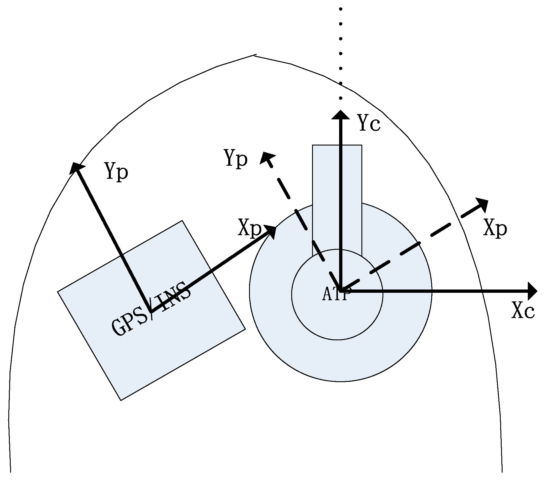
3.2. Installation Error Model

During the installation of the GPS/INS unit, inevitable installation errors are incurred between the measuring axis of the GPS/INS unit and the ATP pointing axis. If there is an error between the installation of the GPS/INS unit and the ATP, the attitude compensation accuracy will be affected and the pointing accuracy of the ATP will decrease. Therefore, after the installation of the GPS/INS unit and ATP, the rotation relationship between the platform coordinate system represented by the GPS/INS unit O - X p Y p Z p and the shipborne ATP deck coordinate system O - X c Y c Z c needs to be calibrated (Figure 4). When measuring the equipment attitude, it is necessary to convert the inertial attitude to the coordinate system of the equipment.
The Equations (8) can be obtained from Equations (3) and (4), and Euler’s theorem:
[ x c y c z c ] = Ψ t ξ t [ x y z ]
We can get from Equations (3) and (4), as shown in Equation (9).
[ L cos E c cos A c L cos E c sin A c L sin E c ] = Ψ t ξ t [ L cos EcosA L cos EsinA L sin E ]
where ( A c , E c ) represents the target polar coordinate in the deck coordinate system, (A, E) represents the target coordinate value in the Northeast celestial coordinate system, ξ t represents the attitude rotation matrix, and Ψ t is the installation error matrix for the shipborne ATP and the GPS/INS unit.
Ψ t is the parameter to be calibrated, Λ c and Λ are coefficient matrices determined by experimental data, and the linear model of installation error can be expressed as Equation (10):
Λ c = Ψ t ξ t Λ + Δ
where, Λ c = [ L cos E c cos A c L cos E c sin A c L sin E c ] , Λ = [ L cos EcosA L cos EsinA L sin E ] , Δ = [ α , β , θ ] T .
The method of “star tracker” is used to evaluate the absolute pointing error of telescope, which is the main method to determine the absolute pointing error of ATP [27]. Because of the high precision of the known positions of stars in the sky, the identification of star signals provides a powerful tool for checking the absolute ATP alignment. In practical application, a star is considered a measurable point in the sky, and the least square fitting technology provides a solution for the absolute pointing error assessment [28].
In fact, we know the theoretical coordinates of the stars ( A i , E i ) in the Northeast celestial coordinate system. When measuring the star using the shipborne ATP, the measured value of the stars ( A c i , E c i ) can be obtained from the deck coordinate system. Several stars in the all-sky region were measured, and the error matrix, Ψ ^ t was obtained by fitting with the least square method.
To sum up, the undetermined parameter Ψ ^ t of the installation error model is calibrated by the least square method, and the residual error Δ is calculated by substituting into Equation (10). We regard residual error Δ as the systematic error of ATP. In the next section, the residual error is further corrected by establishing the shipborne system error correction model to achieve a high absolute pointing accuracy.

3.3. Systematic Errors Model

Due to the influence of machining, installation, and other factors, the telescope contains systematic errors. The error sources include the non-verticality of the horizontal and vertical axes, non-orthogonality of the visual and horizontal axes, and bending of the mirror tube and displacement of the optical axis. For ground telescopes, the research on absolute pointing accuracy correction method is relatively mature [29,30]. But at present there is no good method to complete the high precision systematic error calibration on the mobile platform.
We take the installation error model and systematic error model into consideration, and get the following expression, as shown in Equation (11):
{ Δ A c i = A ^ c i A c i = f ( A c i , E c i ) + ε i , i = 1 , 2 , n Δ E c i = E ^ c i E c i = g ( A c i , E c i ) + τ i , i = 1 , 2 , n
where, ( A ^ c i , E ^ c i ) can be obtained from the equation Λ ^ = Ψ ^ t ξ t Λ , ( Δ A c i , Δ E c i ) are the observation error; f ( A c i , E c i ) and g ( A c i , E c i ) represent the approximate functions with the pointing angles ( A c i , E c i ) as unknowns, that is, the systematic error correction model; ε i and τ i are residual errors.
According to Figure 2, the zero position of the azimuth encoder is no longer aligned with due North, but with the zero position of the fore-and-aft line. Therefore, we consider the deck coordinate system as the reference when designing the error model.
The expression for the mount model [31] is shown in Equation (12):
{ Δ A c i = f ( A c i , E c i ) + ε i = j = 1 m d j ϒ j ( A c i , E c i ) + ε i , i = 1 , 2 , n Δ E c i = g ( A c i , E c i ) + τ i = j = 1 m d j Γ j ( A c i , E c i ) + τ i , i = 1 , 2 , n
where d j , j = 1, 2, …, m are the model coefficients for the m terms; ϒ j ( A c i , E c i ) represents the function in azimuth residual of the azimuth, A c i and elevation E c i of star i, i = 1, 2, …, n; Γ j ( A c i , E c i ) represents the function in elevation residual of the azimuth, A c i and elevation E c i of star i, i = 1, 2, …, n. The ATP mount model is presented in Table 2.

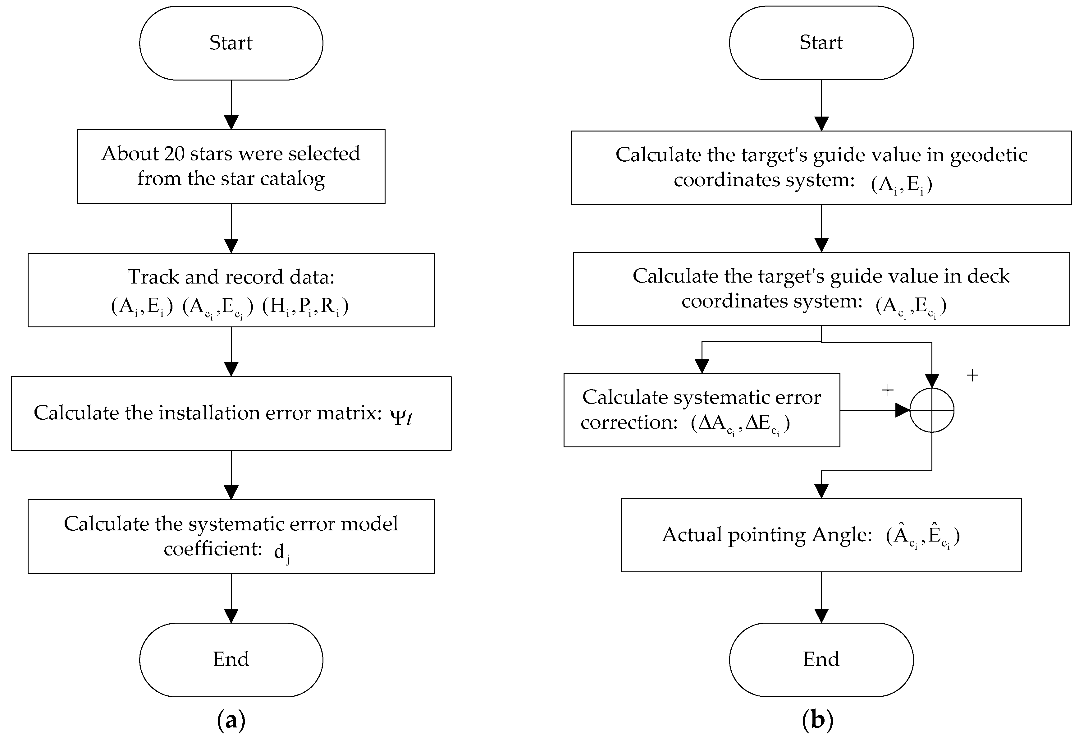
3.4. Installation and Systematic Error Model Calculation and Application Process

The installation and systematic error model can be obtained by the shipborne ATP’s software automatically as shown in Figure 5a. ATP tracks and measures about 20 stars (magnitude less than 6, etc.) uniformly throughout the sky. Then the star’s theoretical position ( A i , E i ) , measurement position ( A c i , E c i ) , and ship attitude ( H i , P i , R i ) can be recorded. Once the measurements are available, the telescope will automatically track and measure the next star. The installation error matrix and systematic error model are solved by the least square method after all the stars measurement data are obtained. The whole process takes less than 10 min.
In the acquisition mode, the ideal point angle (A, E) in the Northeast celestial coordinate system is calculated according to the relationship between the target guidance position and the position of the ship. According to the measured attitude (H, P, R) and the installation error matrix Ψ t , the guidance value ( A c , E c ) in the deck coordinate system can be calculated. Then, according to the pointing error correction model, the pointing error ( Δ A c , Δ E c ) corresponding to the ( A c , E c ) pointing angle is solved. Finally, the pointing error ( Δ A c , Δ E c ) is used to correct the actual pointing angle ( A c , E c ) , and the correct pointing angle ( A ^ c , E ^ c ) is obtained as shown in Figure 5b.

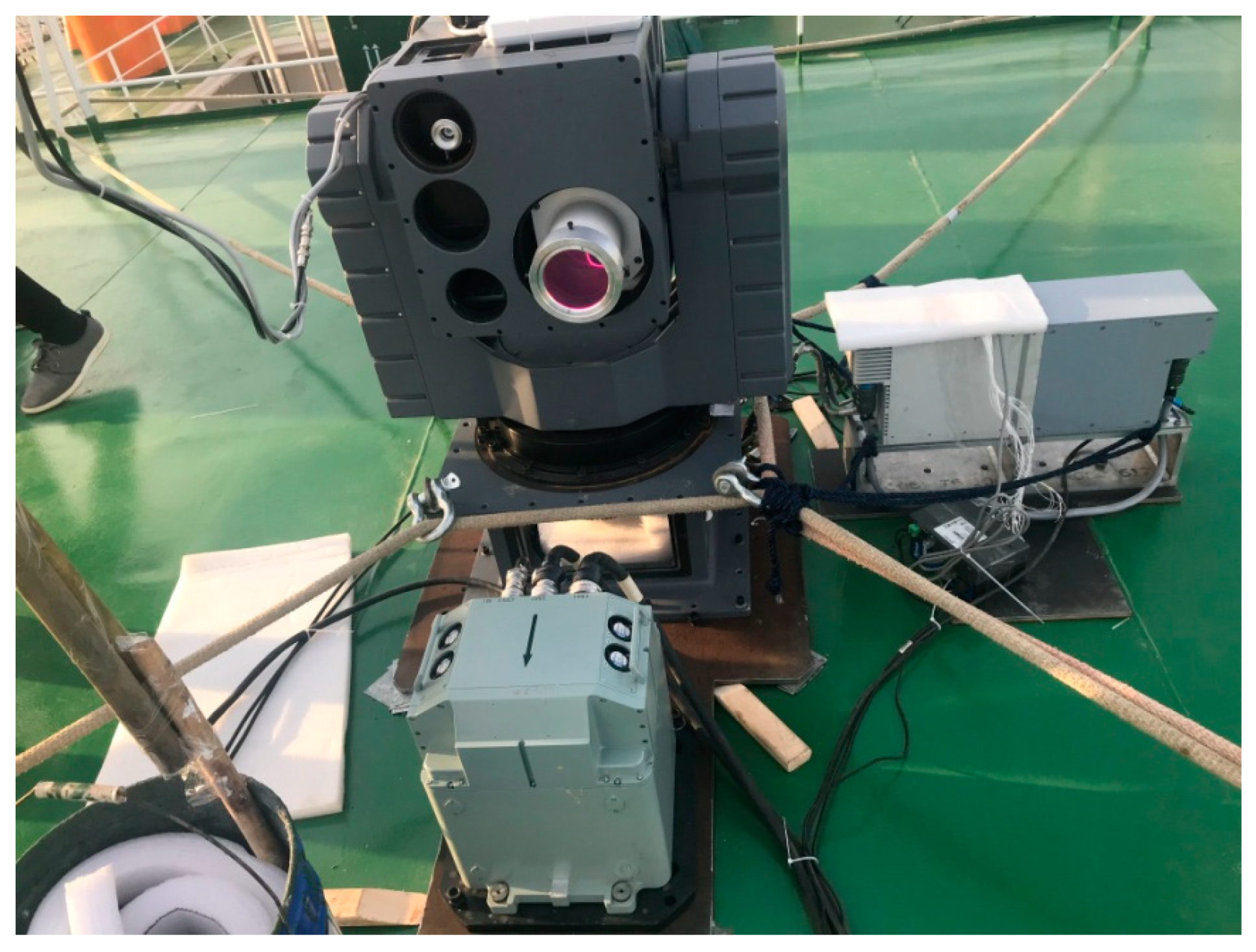
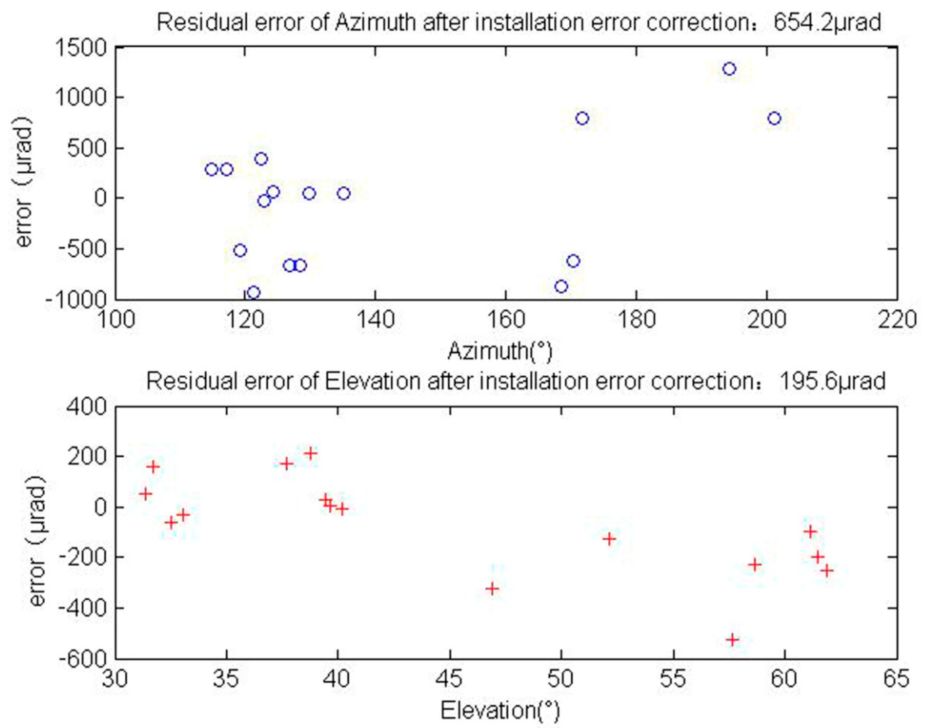
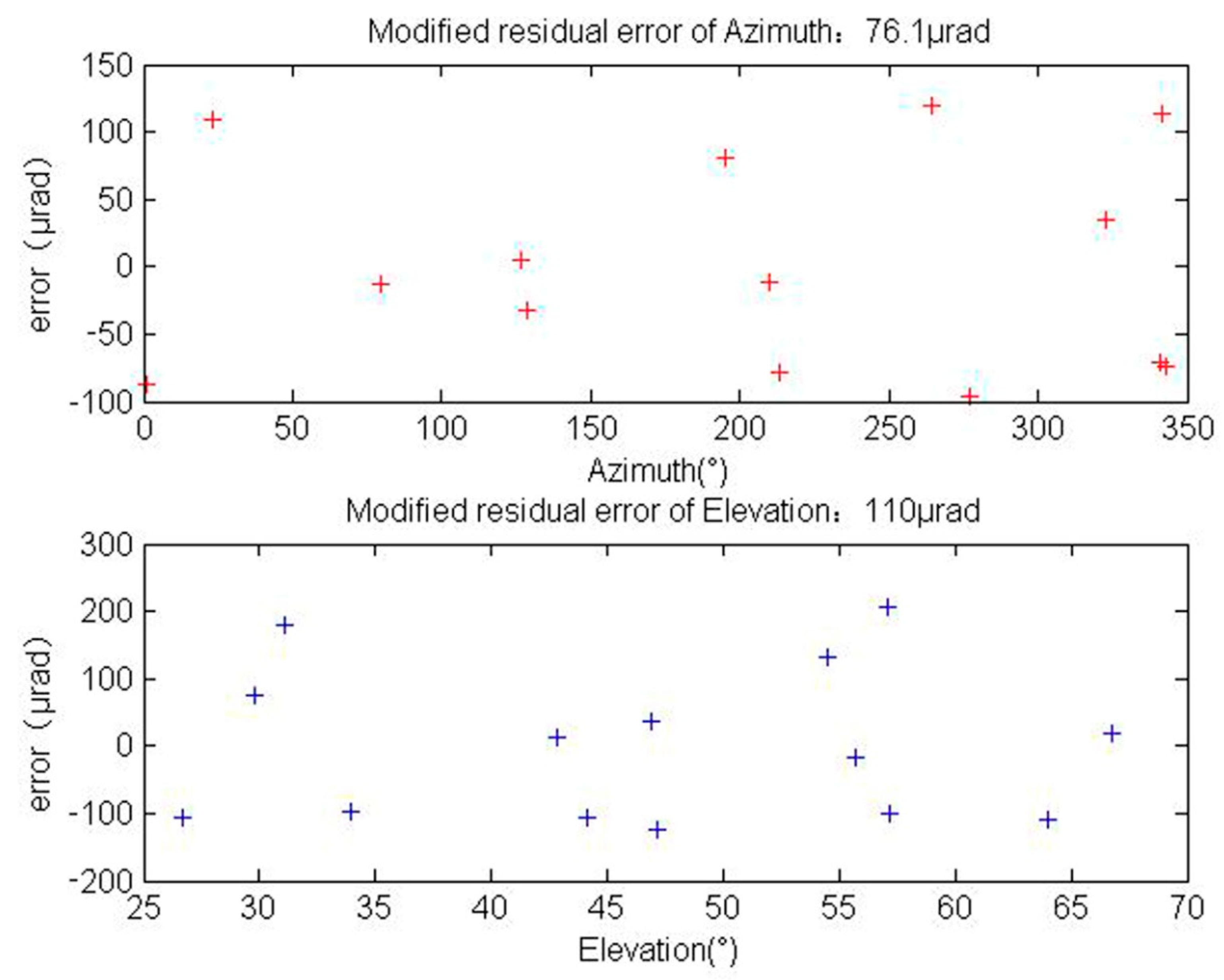
4. Experiment and Results

We developed a shipborne ATP system (Figure 6) mainly to verify the ability for acquisition and pointing, hence, a fast-steering mirror was not used at the fine pointing stage. The primary mirror in the ATP system is a reflecting Cassegrain telescope with an aperture of 75 mm and a focal length of 200 mm. The coarse-control loop included a two-axis gimbal telescope (azimuth rotation range of about −360° to +360°, elevation rotation range of about −5° to +90°) and a CCD camera (FOV of 0.97° × 0.91°, frame rate of 50 Hz).
We set up the ATP system terminal on an experimental ship at Dalian city. After the installation of the ATP system, the experimental ship sailed to an experimental site (38°48.027′ N, 121°50.037′ E) in the sea. We calibrated the ATP system’s pointing ability by tracking and measuring a batch of stars one hour before the experiment. The residual error after installation error correction is shown in Figure 7 while the residual error after systematic error correction is shown in Figure 8. After obtaining the ATP system error model, a batch of stars were tracked and measured to verify the accuracy of the system error model. We used the shipborne ATP to track 15 stars with open-loop and obtained the pointing accuracy. The absolute pointing error obtained for the shipborne ATP azimuth was117.8μrad whereas the elevation was 128.1μrad (Figure 9). The total pointing error of ATP is given by δ pointing   error , as shown Equation (13).
δ pointing   error = δ azimuth 2 + δ elevation 2 = 0.174   mrad
Figure 10 shows the performance of the shipborne ATP with respect to the acquisition and tracking of a satellite. The azimuth and elevation tracking errors were both less than 20μrad (RMS). The azimuth initial acquisition error was 310μrad whereas the elevation initial acquisition error was160μrad. This error includes the orbital error of the satellite.

5. Conclusions

We tracked some stars at sea, achieving a pointing accuracy of less than 180μrad. We acquired and tracked some Low-Earth-orbit satellites at sea, achieving a tracking accuracy of about 20μrad. In this work, we have taken other sources of error into account, including position and alignment errors. The initial coarse orientation of the ATP was based on the satellite’s predicted orbital position, with an uncertainty generally less than 200 m.A position error is less than 0.1mrad at 2000 km. An alignment error of less than 0.05mradcan be achieved between the beacon laser and tracking camera after adjustment. We can obtain a total initial open-loop pointing error of less than 0.324mrad, including position error (less than 0.1mrad at 2000 km), pointing error (less than 0.174mrad), and alignment error between the beacon laser and tracking camera (less than 0.05mrad). In accordance with two-dimensional Gaussian distributions, if the acquisition probability reaches 98.9%, the initial open-loop pointing error (RMS) of the shipborne ATP must be less than one-sixth of the beacon divergence angle. If the divergence angle of the ATP uplink beacon laser is greater than 2mrad, the shipborne ATP system open-loop pointing beacon laser spot can irradiate the satellite. Therefore, by verifying the pointing accuracy of the shipborne ATP and selecting the appropriate divergence angle for the uplink beacon, optical links between the shipborne ATP and the satellite can be established. We achieved significant experimental results for the shipborne ATP acquisition and tracking that will contribute to the realization of laser communication in free space between satellites and the sea.

Author Contributions

Conceptualization, D.H. and Y.H.; funding acquisition, Y.T., G.R., B.Q. and Y.H.; investigation, Q.W. and Z.S.; methodology, D.H., Q.W., Z.S., J.R. and Y.C.; project administration, Y.T.; resources, X.L., Z.S., J.Z., Z.W., T.Z., J.R. and Y.C.; software, D.H., Q.W., X.L., C.G., T.Z. and X.Q.; supervision, G.R., B.Q. and Y.H.; validation, X.L., J.Z. and C.G.; visualization, Z.W. and X.Q.; writing—original draft, D.H.; writing—review & editing, D.H.

Funding

This research was funded by the Natural National Science Foundation of China (NSFC), grant number (U1738204).

Acknowledgments

Thanks to our colleagues in the Key Laboratory of Optical Engineering, Chinese Academy of Sciences. Thanks for the financial support from Youth Innovation Promotion Association, Chinese Academy of Sciences.

Conflicts of Interest

The authors declare no conflict of interest.

References

  1. Chan, V.W.S. Free-space optical communications. J. Light. Technol. 2007, 24, 4750–4762. [Google Scholar] [CrossRef]
  2. Das, S.; Henniger, H.; Epple, B.; Moore, C.I.; Rabinovich, W.; Sova, R.; Young, D. Requirements and challenges for tactical free-space Lasercomm. In Proceedings of the MILCOM 2008-2008 IEEE Military Communications Conference, San Diego, CA, USA, 16–19 November 2008; IEEE: Piscataway, NJ, USA, 2009. [Google Scholar]
  3. Kim, I.I. Wireless optical transmission of fast ethernet, FDDI, ATM, and ESCON protocol data using the Terra Link laser communication system. Opt. Eng. 1998, 37, 3143. [Google Scholar] [CrossRef]
  4. Kim, I.I. Comparison of laser beam propagation at 785 nm and 1550 nm in fog and haze for optical wireless communications. Proc. SPIE 2001, 4214, 26–37. [Google Scholar]
  5. Maynard, J.A.; Begley, D. Airborne laser communications: Past, present and future. Proc. SPIE Int. Soc. Opt. Eng. 2005, 5892. [Google Scholar] [CrossRef]
  6. Fletcher, T.M.; Cunningham, J.; Baber, D.; Wickholm, D.; Goode, T.; Gaughan, B.; Burgan, S.; Deck, A.; Young, D.W.; Juarez, J.; et al. Observations of atmospheric effects for FALCON laser communication system flight test. Proc. SPIE 2011, 8038, 80380F-1–80380F-12. [Google Scholar]
  7. Moll, F.; Horwath, J.; Shrestha, A.; Brechtelsbauer, M.; Fuchs, C.; Navajas, L.A.M.; Souto, A.M.L.; González, D.D. Demonstration of high-rate laser communications from a fast airborne platform. IEEE J. Sel. Areas Commun. 2015, 33, 1985–1995. [Google Scholar] [CrossRef]
  8. Guelman, M.; Kogan, A.; Kazarian, A.; Livne, A.; Orenstein, M.; Michalik, H. Acquisition and pointing control for inter-satellite laser communications. IEEE Trans. Aerosp. Electron. Syst. 2004, 40, 1239–1248. [Google Scholar] [CrossRef]
  9. Sodnik, Z.; Furch, B.; Lutz, H. Optical inter satellite communication. IEEE J. Sel. Top. Quantum Electron. 2010, 16, 1051–1057. [Google Scholar] [CrossRef]
  10. Toyoshima, M.; Takayama, Y.; Takahashi, T.; Suzuki, K.; Kimura, S.; Takizawa, K.; Kuri, T.; Klaus, W.; Toyoda, M.; Kunimori, H.; et al. Ground-to-satellite laser communication experiments. IEEE Aerosp. Electron. Syst. Mag. 2008, 23, 10–18. [Google Scholar] [CrossRef]
  11. Boroson, D.M.; Robinson, B.S. The lunar laser communication demonstration: NASA’s first step toward very high data rate support of science and exploration missions. Space Sci. Rev. 2014, 185, 115–128. [Google Scholar] [CrossRef]
  12. Robinson, B.S.; Boroson, D.M.; Burianek, D.A.; Murphy, D.V. The lunar laser communications demonstration. In Proceedings of the 2011 International Conference on Space Optical Systems and Applications (ICSOS), Santa Monica, CA, USA, 11–13 May 2011; IEEE: Piscataway, NJ, USA, 2011. [Google Scholar]
  13. Wang, J.; Lv, J.; Zhao, G.; Wang, G. Free-space laser communication system with rapid acquisition based on astronomical telescopes. Opt. Express 2015, 23, 20655–20667. [Google Scholar] [CrossRef] [PubMed]
  14. Wuchenich, D.M.R.; Mahrdt, C.; Sheard, B.S.; Francis, S.P.; Spero, R.E.; Miller, J.; Mow-Lowry, C.M.; Ward, R.L.; Klipstein, W.M.; Heinzel, G.; et al. Laser link acquisition demonstration for the GRACE Follow-On mission. Opt. Express 2014, 22, 11351–11366. [Google Scholar] [CrossRef] [PubMed]
  15. Yin, J.; Cao, Y.; Li, Y.H.; Liao, S.; Zhang, L.; Ren, J.; Cai, W.; Liu, W.; Li, B.; Dai, H.; et al. Satellite-based entanglement distribution over 1200 kilometers. Science 2017, 356, 1140–1144. [Google Scholar] [CrossRef] [PubMed] [Green Version]
  16. Liao, S.K.; Cai, W.Q.; Liu, W.Y.; Zhang, L.; Li, Y.; Ren, J.; Yin, J.; Shen, Q.; Cao, Y.; Li, Z.; et al. Satellite-to-ground quantum key distribution. Nature 2017, 549, 43–47. [Google Scholar] [CrossRef] [PubMed] [Green Version]
  17. Rabinovich, W.S.; Moore, C.I.; Mahon, R.; Goetz, P.G.; Burris, H.R.; Ferraro, M.S.; Murphy, J.L.; Thomas, L.M.; Gilbreath, G.C.; Vilcheck, M.; et al. Free-space optical communications research and demonstrations at the US Naval Research Laboratory. Appl. Opt. 2015, 54, F189–F200. [Google Scholar] [CrossRef] [PubMed]
  18. Gilbreath, G.C.; Rabinovich, W.S.; Moore, C.I.; Burris, H.R.; Mahon, R.; Grant, K.J.; Goetz, P.G.; Murphy, J.L.; Voelz, D.G.; Ricklin, J.C.; et al. Progress in laser propagation in a maritime environment at the Naval Research Laboratory. In Proceedings of the Free-Space Laser Communications V, SPIE Optics & Photonics 2005, San Diego, CA, USA, 31 July 2005; SPIE: Bellingham, WA, USA, 2005; Volume 5892, pp. 605–613. [Google Scholar]
  19. Wu, R.; Zhao, X.; Liu, Y.; Song, Y. Initial pointing technology of line of sight and its experimental testing in dynamic laser communication system. IEEE Photonics J. 2019, 11, 1–8. [Google Scholar] [CrossRef]
  20. Zhao, X.; Liu, Y.Q.; Song, Y. Line of sight pointing technology for laser communication system between aircrafts. Opt. Eng. 2017, 56, 126107. [Google Scholar] [CrossRef]
  21. Klein, M.B.; Sipman, R.H. Large aperture Stark modulated retroreflector at 10.8 microns. J. Appl. Phys. 1980, 51, 6101–6104. [Google Scholar] [CrossRef]
  22. Rabinovich, W.S.; Mahon, R.; Gilbreath, G.C.; Burris, R.; Goetz, P.G.; Moore, C.I.; Ferraro-Stell, M.; Witkowsky, J.L.; Swingen, L.; Oh, E.; et al. Free-space optical communication link at 1550 nm using multiple quantum well modulating retro-reflectors over a 1-kilometer range. In Proceedings of the Conference on Lasers and Electro-Optics, 2003, CLEO ’03, Baltimore, MD, USA, 6 June 2003; IEEE: Piscataway, NJ, USA, 2004. [Google Scholar]
  23. Rabinovich, W.S.; Goetz, P.G.; Mahon, R.; Swingen, L.A.; Murphy, J.L.; Ferraro, M.; Burris, H.R.; Moore, C.I.; Suite, M.R.; Gilbreath, G.C.; et al. 45-Mbit/s cat’s-eye modulating retroreflectors. Opt. Eng. 2007, 46, 104001. [Google Scholar] [CrossRef]
  24. Peter, G.G.; Mahon, R.; James, L.M.; Mike, S.F.; Michele, R.S.; Walter, R.S.; Ben, B.X.; Harris, R.B.; Christopher, I.M.; William, S.R.; et al. Modulating retro-reflector lasercom systems at the Naval Research Laboratory. In Proceedings of the Military Communications Conference, 2010-MILCOM, San Jose, CA, USA, 31 October–3 November 2010; IEEE: Piscataway, NJ, USA, 2010. [Google Scholar]
  25. Majumdar, A.K. Modulating retroreflector-based free-space optical (FSO) communications. In Advanced Free Space Optics (FSO); Springer: New York, NY, USA, 2015. [Google Scholar]
  26. Mutilba, U.; Kortaberria, G.; Egaña, F.; Yagüe-Fabra, J.A. 3D Measurement Simulation and Relative Pointing Error Verification of the Telescope Mount Assembly Subsystem for the Large Synoptic Survey Telescope. Sensors 2018, 18, 3023. [Google Scholar] [CrossRef]
  27. Huang, L.; Ma, W.; Huang, J. Modeling and calibration of pointing errors with alt-az telescope. New Astron. 2016, 47, 105–110. [Google Scholar] [CrossRef]
  28. Tiziani, D.; Garczarczyk, M.; Oakes, L.; Schwanke, U.; van Eldik, C. A Pointing Solution for the Medium Size Telescopes for the Cherenkov Telescope Array. AIP Conf. Proc. 2017. [Google Scholar] [CrossRef]
  29. Cheng, J. The Principles of Astronomical Telescope Design; Springer: New York, NY, USA, 2009. [Google Scholar]
  30. Donato, C.D.; Prouza, M.; Sanchez, F.; Santander, M.; Camin, D.; Garcia, B.; Grassi, V.; Grygar, J.; Hrabovský, M.; Řídký, J.; et al. Using stars to determine the absolute pointing of the fluorescence detector telescopes of the Pierre Auger Observatory. Astropart. Phys. 2007, 28, 216–231. [Google Scholar] [CrossRef]
  31. Luck, J. Mount Model Stability. In Proceedings of the 14th International Workshop on Laser Ranging Instrumentation, San Fernando, Spain, 7–11 June 2004. [Google Scholar]
Figure 1. Schematic of acquisition and tracking. (a) The shipborne acquisition, tracking, and pointing (ATP) system initiates the acquisition process. The shipborne ATP and satellite activate their beacon lasers and point at each other using the predicted ephemeris. (b) The satellite detects the uplink beacon laser and initiates precise tracking. (c) The shipborne ATP detects the downlink beacon laser and initiates precise tracking. (d) Bidirectional tracking and locking between the satellite and shipborne ATP is established until the laser communication is terminated.
Applsci 09 03940 g001
Figure 2. Schematic diagram of coordinate system and attitude angle. (a) The Northeast celestial coordinate system O-XYZ. (b) The deck coordinate system O - X c Y c Z c . (c) Definition of attitude angle.
Applsci 09 03940 g002
Figure 3. Attitude pre-compensation unit.
Applsci 09 03940 g003
Figure 4. Error relation between the shipborne ATP and the GPS/INS unit.
Applsci 09 03940 g004
Figure 5. Installation and systematic error model calculation and application process. (a) Installation and system error model calculation flow chart. (b) Flow chart of actual use.
Applsci 09 03940 g005
Figure 6. The shipborne ATP system. The shipborne ATP system shows the uplink beacon, coarse camera, and the attitude pre-compensation unit.
Applsci 09 03940 g006
Figure 7. Residual error after installation error calibration. The azimuth residual error is 654.2μrad while the elevation residual error is 195.6μrad.
Applsci 09 03940 g007
Figure 8. Residual error after systematic error correction. The azimuth residual error was obtained as 76.1μrad while the elevation residual error was110μrad.
Applsci 09 03940 g008
Figure 9. Pointing error of azimuth and elevation. Azimuth pointing error is 117.8μrad and elevation pointing error is 128.1μrad.
Applsci 09 03940 g009
Figure 10. The shipborne ATP acquired and tracked the performance of a satellite. (a) The tracking error for the entire process and the initial error just appear in the field of view. The azimuth initial acquisition error was 310μrad whereas the elevation initial acquisition error was 160μrad. When the spot was in the tracking field, the azimuth tracking error was about 19.5μrad (RMS) while the elevation tracking error was about 14.6μrad (RMS). The tracking error in the stabilized time lasted from 10:15:58 to 10:21:28, about 330 seconds. (b) Ship attitude measurement. The yaw, pitch, and roll curves of the ship measured by the GPS/INS unit.
Applsci 09 03940 g010
Table 1. GPS/INS unit attitude measurement accuracy.
AttitudeangleAccuracy
Yaw≤0.18mrad (RMS)
Roll and pitch≤0.09mrad (RMS)
Table 2. The ATP mount model.
TermDescriptionAzimuth Function ( ϒ ) Elevation Function ( Γ )
1.Azimuth encoder offset1-
2.Elevation encoder offset-1
3.Azimuth axis tilt about fore-and-aft line cos A c tan E c sin A c
4.Azimuth axis tilt about axis Yc sin A c tan E c cos A c
5.optical axis misalign sec E c -
6.Non-orthogonality of Azimuth and Elevation axes tan E c -
7.Azimuth bearing ellipticity (sin) sin A c -
8.Azimuth bearing ellipticity (cos) cos A c -
9.Azimuth bearing ellipticity (sin)- sin E c
10.Azimuth bearing ellipticity (cos)- cos E c
11.Telescope tube flexure- cot E c
12.Azimuth encoder scale error A c / 2 π -
13.Elevation encoder scale error- E c / 2 π
14.Bi-periodic in azimuth cos 2 A c -
15.Elevation encoder stiction - sin A c
16.Elevation bearing stiction- E c sin A c

