1. Introduction
Predicting the penetration depth of the projectile is one of the essential aspects of the geometric design of the projectile [
1]. In particular, projectiles are expensive, preparation and experiments of projectiles take so much time and cost. Additionally, the effects of design variables are challenging to study accurately due to measuring errors and experiment problems.
Recent developments in computational capabilities and techniques have made computational simulation very efficient in many ways [
2,
3]. Simulation considering deformation of the projectile and the target costs too much computational time. Also, the deformation and fracture characteristics of the target and the contact problem between the target and the projectile are required [
4].
Thus, a theoretical and empirical based model for penetration has been developed for rapid prediction. Young [
5] developed an empirical-based simple analytic equation for predicting the penetration depth of the projectile. Young’s equation was derived based on the energy method and some empirical variables. The advantage of Young’s equation is that the calculation time is short, and the use is simple. However, in the calculation, the deformation of the projectile is not calculated. It is difficult to apply to various environments.
Another method considering lateral loading was developed based on Young’s equation [
6]. The calculation was completed with small time increments. The reaction forces were calculated from Young’s equation and applied to the projectile with an explicit method. However, it was not possible to consider the change of the reaction force with respect to deformation of the projectile.
The cavity pressure method [
7,
8,
9] is an analytical method that calculates the reaction forces resulting from targets with respect to the expansion speed of the cavity. Normal pressure on the projectile nose is approximated by the results from the radial stress on the cavity surface. Forrestal and Luk [
7] developed penetration equations for soil targets with Mohr-Columb and Tresca yield criteria. According to the yield criteria, the boundary condition of the elastic-plastic interface is different. Forrestal and Tzou [
8] developed a spherical cavity-expansion penetration model for concrete targets for an incompressible and compressible material. Warren and Forrestal [
10] derived a spherical cavity pressure distribution of the aluminum plate, considering compressible, strain hardening, and strain-rate dependence. The integration of the projectile surface with the cavity pressure presents axial reaction forces. From Newton’s law, the acceleration and the penetration depth of the projectile were calculated. However, the cavity pressure method cannot consider the deformation of the projectile. When the deformation of the projectile is extensive (i.e., aluminum target), the cavity pressure method is not proper.
There have been some studies regarding the effects of the projectile geometries. Chen and Li [
11] studied the effect of a non-deformable projectile having different geometrical characteristics on the penetration with the cavity expansion method. A general geometry function was introduced to define the geometrical characteristics of the projectile. When deformation of the projectile is very small, the prediction of the penetration using the cavity-expansion method is appropriate. He et al. [
12] studied the penetration and perforation of the fiber-reinforced plastic (FRP) laminate with rigid projectiles.
The finite cavity method [
13] is a method that links the advantages of finite element analysis with the advantages of analytical methods. Cavity pressure calculates the pressure distribution at this point when the point moves at a certain speed and calculates the reaction forces of the projectile. Finite element analysis was applied to predict the deformation and trajectory of the projectile. Fang et al. [
14] and Kong et al. [
15] conducted simulations of the projectile to consider the free-surface effect and the multi-layer effect with the finite cavity pressure method. It was found that the simulation was efficient and showed good agreements with the experimental results.
In this study, the penetration depth of a projectile was predicted using the finite cavity pressure method. In particular, the penetration depth with respect to the projectile geometry was analyzed using the finite cavity pressure method. Projectiles with a cylindrical geometry, a conical geometry, and an ogive nose were compared in the normal and oblique impacts. Through this study, the relationship between the deformation and the penetration depth of the projectile was analyzed. The relationship of the projectile geometry that can increase the penetration depth was studied.
2. Prediction of Penetration Depth Using the Finite Cavity Pressure Method
2.1. Cavity Pressure Method
Analytic calculation methods for penetration depth began with Bishop et al. [
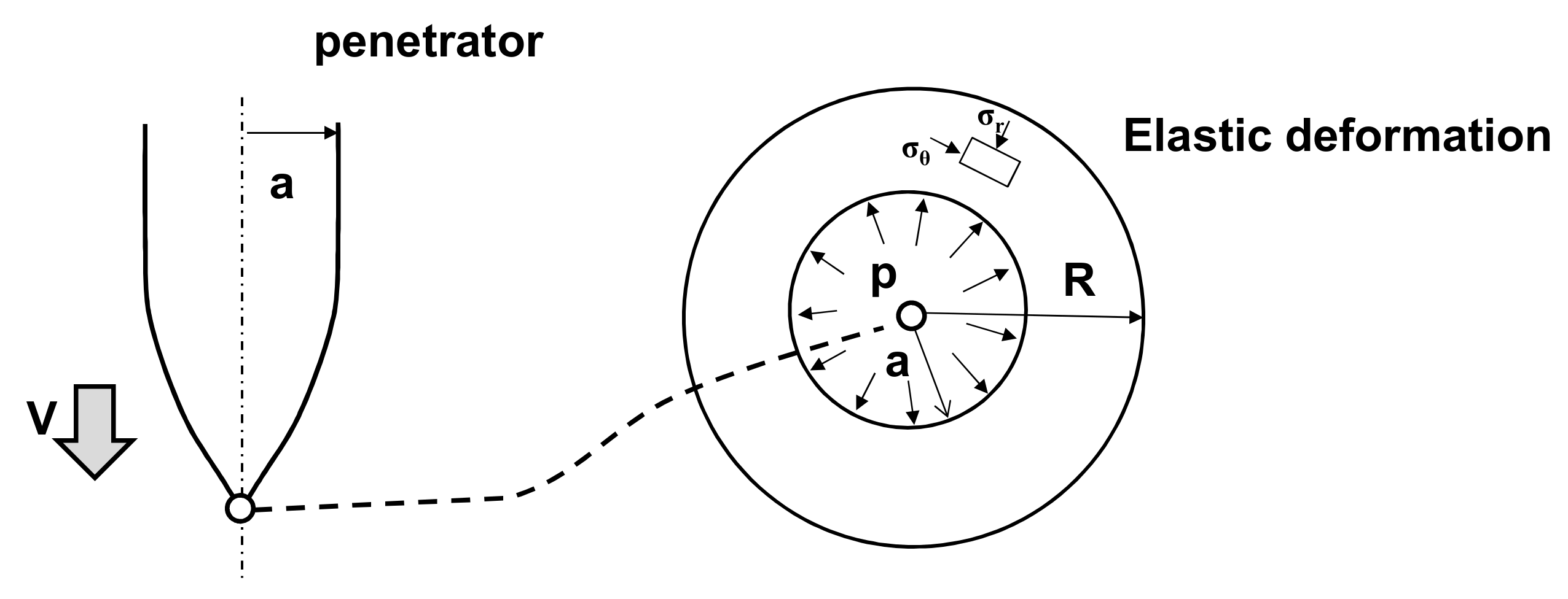
16]. Spherical cavity expansion models approximate a two-dimensional target response with equations derived from cavity expansion analyses. A schematic figure of the cavity pressure at the tip is shown in
Figure 1. A spherical cavity expanded from the initial radius with a constant velocity V. As the spherical cavity expands, response regions were developed following plastic and elastic response regions [
9,
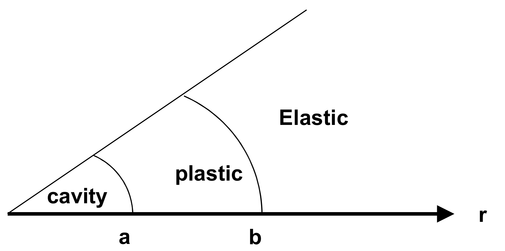
10]. The distribution of the cavity pressure is shown in
Figure 2. The plastic region starts at the radius of b, and the elastic region begins at the radius of d. Cavity pressure was employed as an equation of penetration equations. From the equations of momentum and mass conservation with spherical symmetry, the pressure distribution can be calculated.
The cavity pressure model depends on the target material property. Therefore, an appropriate cavity pressure model should be used. In this work, the target material was a 6061-T6511 aluminum plate. For this material, the compressible cavity pressure model considering strain hardening and strain rate dependency can precisely predict the response of the material [
10]. Instead of using complex equations, the cavity pressure model was approximated with a second-order equation [
10]. From the least square fit to the calculated pressure distribution with respect to the particle velocity (v), a normalized equation in Equation (1) was obtained.
In Equation (1), v is the expansion speed of the cavity; Y is the yield stress of the target material;
ρ0 is the density of the material; A, B, and C are fitting coefficients. According to the material property and material model, the values of coefficients are varying. The value of coefficients of A, B, and C for a 6061-T6511 aluminum considering strain hardening and strain rate dependency are 5.039, 0.983, and 0.940, respectively. This model is suitable for 300 m/s to 1200 m/s [
10].
2.2. Finite Cavity Pressure Method
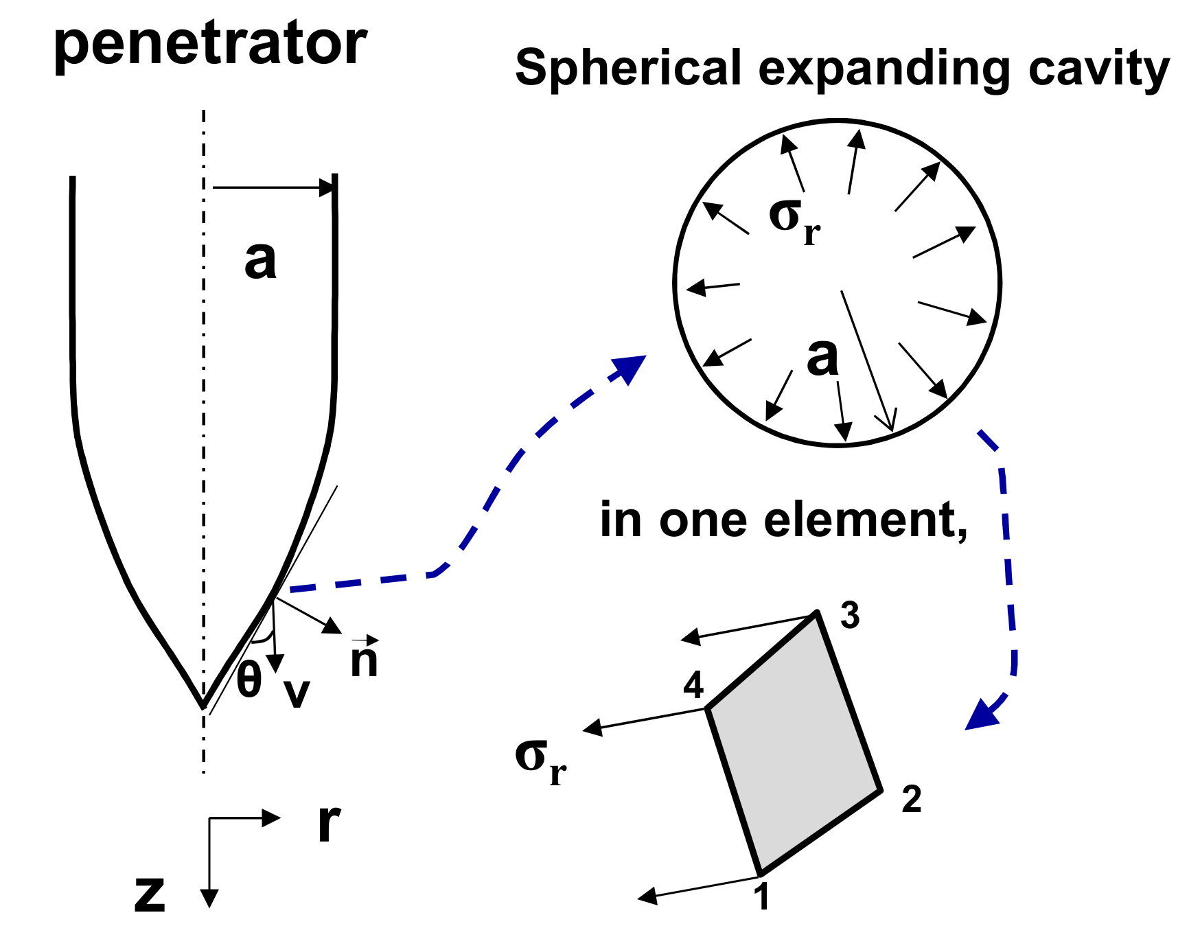
The finite cavity pressure method is an application method for predicting the penetration depth of a projectile. The main difference between the analytical method using cavity pressure and the finite cavity pressure method is that the deformable projectile is employed and the pressure is applied to each element of the projectile in the finite cavity pressure method. The pressure normal to the surface of the projectile acts as a reaction pressure to penetration into the target. The projectile was modeled as a solid element such as hexahedral elements. As a result, the deformation and kinetics of the projectile can be calculated. The pressure was assumed to be applied to each node of the element, as shown in
Figure 3 and applied in the finite element analysis as a boundary condition.
Equation (2) presents the pressure at each node where
is the nodal velocity,
is the unit normal vector of the corresponding element. Y
0 is the yield stress of the material, and ρ
0 is the density of the projectile material. Coefficients such as A, B, and C are defined from the cavity pressure method. In this work, the target was the aluminum plate. The cavity pressure of the previous work [
17] was employed.
The effective velocity of the element was defined as , which means the dot product of the element normal direction and the velocity vector of the node. For example, if the angle between the normal direction of the element and the velocity of the projectile is perpendicular, the effective velocity is zero. Consequently, no pressure is applied to the element. In this work, the finite cavity pressure method was employed in the ABAQUS/Explicit using the user load subroutine VDLOAD. User subroutine VDLOAD defines the magnitude of the distributed load as a function of position, velocity, and time. The calculating procedures are as follows: First, the velocity and the normal direction of the projectile were calculated. Next, the corresponding cavity pressure (σr) was calculated. Finally, the deformation of the projectile was calculated.
In the full simulation model, the projectile and the target should be modeled with very fine mesh with appropriate contact conditions and material properties. However, in the finite cavity pressure method, only the projectile was modeled with solid elements. The material property of the target and the contact between the target and the projectile was not considered. The interaction between the target and the projectile was the cavity pressure distribution with respect to only the cavity speed.
2.3. Free Surface Effect
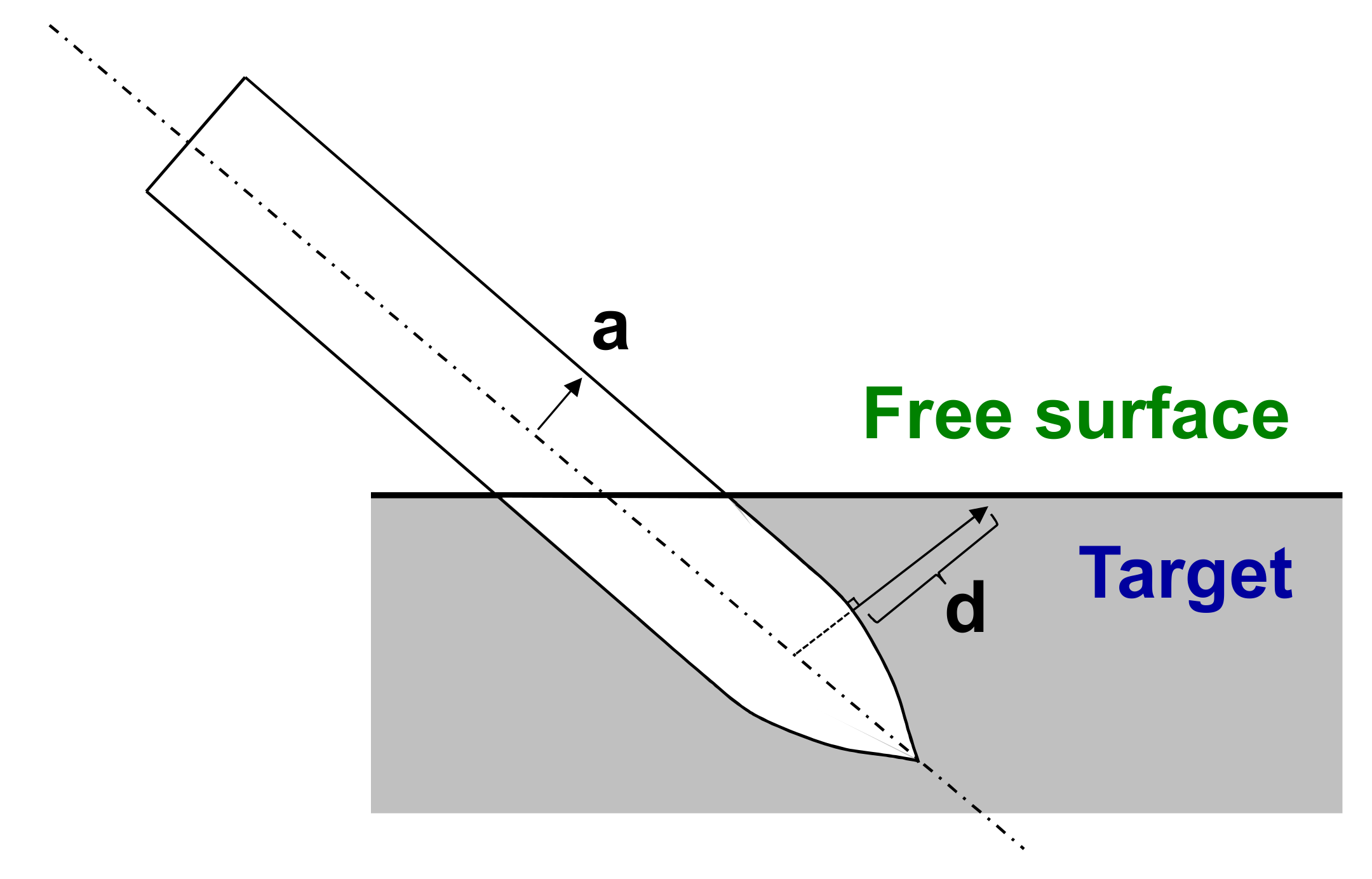
The cavity pressure was calculated from the assumption that the target material is infinite. When the distance between the projectile and target is short, the pressure applied to the element is low compared to the normal. The free surface effect means that when the position of the projectile is near the ground, no pressure is generated because the cavity pressure is not perfectly formed at that part of the projectile. In order to consider the reduced cavity pressure on the surface near the target, Forrestal and Luk [
13] proposed the following method.
In the calculation of the factor for the free surface effect, the aluminum material was considered as perfectly plastic and incompressible. In the calculation of the cavity pressure, a spherical cavity expansion problem with the infinite boundary and the finite boundary were employed. A schematic figure describing the free surface effect is presented in
Figure 4. Warren and Poormon [
17] derived the decay function, which is a function of d, a, and v and demonstrates the free surface effect.
First, calculate the pressure acting at an infinite distance from the particle. Then calculate the pressure at a certain distance. The pressure ratio at a certain distance can be obtained through the air ratio. As shown in
Figure 2, the interface between the elastic region and the plastic region should be defined. For an incompressible material, the elastic-plastic interface (b) is defined as follows:
where a is the radius of the cavity. For metal materials, the pressure distribution depends on d. For the plastic region (d < b), the decaying function is defined as follows:
For the elastic region (d ≥ b), the decaying function is defined as follows:
Finally, the general solution according to d, a, and v is defined as follows:
The aforementioned equation presents a cavity pressure distribution with respect to dI and vI. The first equation presents the compressibility, strain hardening, and strain rate dependent cavity pressure of the aluminum materials. The following equation is the decaying function and presents the effects of the free surface effects.
4. Results and Discussions
4.1. Verification Model
To verify the simulation model in this work, simulation results were compared to the penetration experiments of previous works. Warren and Poormon [
17] examined an oblique impact test using the projectile having an ogive nose with the CRH value of 3 (CRH = 3) at various impact velocities and angles. The comparisons were conducted with the impact angle of 15° and 30°, which are presented in the previous works. Collision with the angle of 30° was analyzed for 1156 m/s and 753 m/s. Collision with the angle of 15° was investigated for 1209 m/s and 985 m/s. The target material was 6061-T6511 aluminum. The projectile material was VAR 4340 steel.
Under the conditions mentioned above, the results of the simulation and the experiment were listed in
Table 1 and showed good agreements. The final coordinates of the projectile tip were (−39.1 mm, 130.7 mm) in the experimental result and (−37.1 mm, 129.55 mm) in the simulation result.
Figure 9a presents the experimental result of the final deformed shape after impact for V = 985m/s, 15
° angle of obliquity.
Figure 9b presents the simulation result of the same conditions. The most significant difference was shown in the case of the impact angle of 30° and the velocity of 1156 m/s. In this case, the final position of the projectile tip showed an error of 17.25% in the Y-directional coordinate. In most other cases, the error is less than 5%. The analysis results showed that the analytical model of this study could predict the results of the experiment precisely considering the problems of measurement and experimental errors.
4.2. Simulation Results of the Normal Impact
In this study, the mass of the projectile varies, depending on the shape of the noses. The penetration characteristics of the projectile were analyzed with the penetration depth per mass of the projectile. The kinetic energy of the projectile was expressed as 0.5 mV2. As the mass of the projectile increases, the kinetic energy proportionally increases. However, the kinetic energy by mass has the same value.
Also, as previously described, the penetration depth of an aluminum target (Al 6061-T6511) was analyzed. The velocity of the projectile was 1208 m/s for all cases. The penetration depth per mass is shown in
Figure 10. The cylinder geometry showed the lowest value with the value of −1.21 m/kg. Blunt shape (−5.69 m/kg), conical shape (−6.23 m/kg), and truncated shape (−7.4 m/kg) are the next.
Among seven projectile geometries, the projectile having the ogive nose showed increased penetration depth. Even with the same category of geometries, the penetration depth per mass varies significantly depending on the CRH value. The penetration depth to mass is 7.75 m/kg with a CRH of 1, 10.51 m/kg with a CRH of 3, and 11.47 m/kg with a CRH of 5.
4.3. Discussion-Effect of Plastic Deformation on the Normal Penetration
In the case of the normal impact, the projectile with an ogive nose showed the deepest penetration. The plastic deformation of the projectile has a significant effect on the penetration depth. The penetration depth of the projectile had a close relationship with its kinetic energy. Before the collision, the projectile had kinetic energy related to the velocity. If there was no energy loss, the kinetic energy changed to penetration energy and the deformation energy of the projectile. As the plastic deformation of the projectile increased, the deformation energy of the projectile increased. The remaining energy was converted into penetration energy.
Figure 11 shows the deformed shapes of the cylinder shape, blunt shape, truncated shape, and ogive shape with the CRH value of 3 (CRH = 3) in normal impact. The transmission depth is the highest in CRH = 3, followed by Truncated, Blunt, and Cylinder, as shown in
Figure 10. In the case of the cylinder geometry, large plastic deformation occurs after impact. As a result, the shape of the projectile is significantly altered. The initial shape cannot be maintained. In the case of blunt geometry, the diameter of the projectile body was increased after impact. Plastic deformation at the tip of the projectile occurs in the truncated geometry, thereby increasing the lower diameter. However, in the case of CRH = 3, the plastic deformation at the center was also very small. The projectile retained its original shape.
Figure 12 presents the velocity, and the displacement of the projectile tip for the cylinder geometry, blunt geometry, truncated geometry, and ogive geometry (CRH = 3). The velocity of the cylinder geometry reduced very quickly. Finally, the velocity of the projectile was converged to zero. For the projectile having an ogive nose (CRH = 3), showed a moderate reduction of the velocity. Consequently, the penetration depth was the largest. The reaction force of the projectile is proportional to the acceleration of the projectile. The cylinder geometry showed the largest acceleration, which is the first derivative of the velocity. It means that a large force occurred at the cylinder geometry.
The graph in
Figure 13 shows the relationship between the plastic deformation energy per mass and the depth of the penetration depth per mass. In
Figure 11d, the maximum equivalent plastic strain is 0.027. The deformation energy of the projectile is very small. Therefore, the remained energy is converted to penetration energy and has good penetration performance. In the case of cylinder shape, plastic deformation is very large, indicating a large amount of plastic deformation energy. Before impact, all have kinetic energy relative to the same mass, where the larger the dispersion to plastic modified energy, the smaller the transmission depth can be found. If there were no nose in the projectile like the cylinder geometry, a strong reaction force due to the impact occurred at the earlier stage of the collision. This energy is converted into the plastic strain deformation of the material.
In the case of the ogive shape, the angle of the nose between the surface of the nose and the center axis of the projectile is small. The cavity pressure occurred due to the impact is low compared to other cases. This greatly increases the depth of penetration. From these results, it was found that the geometry with large CRH value, which has a small angle between the surface of the nose and the center axis showed greater penetration. The deformation of the projectile is very small.
4.4. Simulation Results of the Oblique Impact
For the case of the oblique impact, the final position of the projectile tip was compared. If the position of the
x-axis has a large value, it means that the projectile has moved a lot in the horizontal direction. Movement in the horizontal direction has an adverse effect on the penetration of the projectile. With the same kinetic energy, the ideal case is to penetrate in the travel direction.
Figure 14 presents the coordinate of the projectile tip after impact with the velocity of 1208 m/s and the impact angle of 30°. The dash-dotted line in
Figure 8 presents the line with an angle of 30°, which means the ideal result of the projectile movement. Additionally, the moving trajectories of the projectiles of various projectile geometries were presented in
Figure 14.
The simulation results of the oblique impact are summarized in
Table 2. The final position of the projectile tip can be divided into two lengths. One is the length along the impact angle 30°, which is shown as D
L in
Figure 14. Another is the perpendicular distance to the impact angle which is shown as D
P in
Figure 14. The ratio of the displacement in the normal direction (D
P) to the displacement along the impact angle (D
L) is selected as a measurement which indicates whether the projectile followed the impact angle. When D
P/D
L is small, the projectile follows the impact angle. When D
P/D
L is large, the projectile moved to the perpendicular direction.
The cylinder geometry showed the smallest movement. The reaction forces due to the impact are very large. As a result, the plastic deformation of the projectile is also extensive. This is similar to the normal impact. For the blunt geometry, DP/DL showed the largest value among seven projectile geometries. It was shown that penetration depth is very low in the vertical direction and has moved in the horizontal direction. It means that the projectile cannot penetrate the target in the vertical direction. As the projectile moves, the projectile bends. Finally, the projectile moves along the bending direction.
Conical and truncated geometries do not move along the angle of impact. The bending deformation of the projectile occurred for the aforementioned cases. The ratios of the two cases (DP/DL) are close. However, the projectile with the truncated geometry showed better penetration characteristics.
The projectile with an ogive nose showed different results. For the projectile with an ogive nose with the CRH value of 1, the ratio is 1.021. The projectile moves similarly along the impact angle and the normal direction. Also, the bending deformation of the projectile occurred. However, if the CRH is 3 and 5, the projectile moves not far away from the impact angle. The ratio of the projectile (CRH = 3) is 0.393, and the projectile (CRH = 5) is 0.366. The blunt geometry is that the CRH value is 0.5. So, as the CRH value increases, the projectile moves more accurately along the impact angle. As the CRH value increases, the penetration depth of the projectile is increasing.
4.5. Effect of the Plastic Deformation on the Oblique Impact
The following figures show the deformed shape of various geometries after the oblique impact. In the case of the cylindrical shape, as soon as the projectile strikes, the pressure caused by the collision is concentrated at the end of the cylinder. The direction of the cavity pressure is normal to the bottom surface. Because of the pressure concentration at the bottom surface of the cylinder, the cylindrical projectile shows very large plastic deformation with compressive deformation as shown in
Figure 15a.
For the blunt geometry, there was an asymmetric distribution of the cavity pressure because of the free surface effect, and the bending deformation of the projectile occurred. The maximum equivalent plastic strain was 0.557. The maximum plastic deformation occurred at the center of the projectile. Small pressure was applied to the projectile near the ground the projectile. However, on the opposite side, the depth of the target was considered as infinite, and full pressure was applied. Accordingly, the trajectory of the projectile shows ‘J’ curve. As the bending deformation increases, the projectile further moves horizontally. As bending deformation increases, the path of the projectile’s movement follows the direction of the bending deformation. Accordingly, as shown in
Figure 14, the final coordinate of the projectile in the horizontal direction greatly increased.
The projectile with a truncated geometry has a surface perpendicular to the moving direction. At that surface, the maximum plastic deformation occurred. The equivalent plastic strain was 0.295. Also, due to the asymmetric cavity pressure distribution, the bending deformation occurred. The deformed shape and final position of the projectile are shown in
Figure 15c.
Figure 15d presents the deformed shape and final position of the projectile having an ogive nose. The maximum plastic strain was 0.095, the smallest among four geometries. The bending deformation was very small, and thus, the penetration depth showed the largest value.
From the aforementioned results, the projectile geometry for improved penetration characteristics was studied. When the projectile has a surface perpendicular to the moving direction, the reaction forces from the impact are concentrated on that surface. Consequently, the deformation of the projectile occurred. The loss of the energy changed from kinetic energy to penetration energy. Under the normal impact and the oblique impact, the projectile having an ogive geometry shows the best penetration characteristics. As the CRH value increases, the penetration depth was also increased. Particularly for the oblique impact, as the CRH value increases, the bending deformation of the projectile decreases, thereby greatly increasing the penetration depth of the projectile.
5. Conclusions
In this work, the penetration characteristics of projectiles having a cylinder, conical, blunt, and ogive geometry were investigated using the finite cavity method. Normal and oblique impacts at an impact angle of 30° were compared. The target was a 6061-T6511 aluminum plate. And the material of the projectile was VAR 4340 steel. The projectile tended to be compressed in the normal impact and bent in the oblique impact. In both the normal impact and the oblique impact, the plastic deformation of the projectile had significant effects on the penetration. The cylinder having a surface perpendicular to the moving direction endured large stress during the earlier stage of the impact. Massive cavity pressure is applied on the surface having the normal direction to the velocity at the earlier stage of the impact. The reaction forces are very enormous; as a result, the acceleration of the projectile is large. Due to the concentrated force, large plastic deformation occurs. The projectile having an ogive nose with a CRH value of 5 showed the smallest plastic deformation after impact and the best penetration performance. For the projectile having an ogive geometry, the length of the nose depended on the CRH value. As the CRH value increased, the length of the nose increased. At the same time, the angle of the tip between the center-axis of the projectile decreased. The decrease in the angle resulted in the cavity pressure at the projectile surface decreasing. Finally, the projectile having an ogive nose with high CRH value resulted in increased penetration depth.


