Article

Analysis of a Feasibility Study of a Precision Grinding Process for Industrial Blades Used in the Cutting of Soft Tissues by a Prototype 5-Axis CNC Grinding Machine

by
Bartosz Zieliński
1,
Wojciech Kapłonek
2,
Marzena Sutowska
2 and
Krzysztof Nadolny
2,*
1
Espersen Koszalin Sp. o.o., Mieszka I 29, 75-124 Koszalin, Poland
2
Department of Production Engineering, Faculty of Mechanical Engineering, Koszalin University of Technology, Racławicka 15-17, 75-620 Koszalin, Poland
*
Author to whom correspondence should be addressed.
Appl. Sci. 2019, 9(18), 3883; https://doi.org/10.3390/app9183883
Submission received: 12 June 2019 / Revised: 12 September 2019 / Accepted: 12 September 2019 / Published: 16 September 2019
(This article belongs to the Section Applied Industrial Technologies)

Abstract

:
Obtaining a high quality product (filet) is often necessary to effectively separate the soft tissues of fish raw material. An intensive technological process and a number of unfavorable factors can generate the wear of low-stiffness planar industrial cutting blades used for this purpose. The relatively short time of efficient work of the blade causes the production stoppages needed for its exchange, which consequently can inflict significant financial losses. The wear of industrial cutting blades is one of the important and still unsatisfactorily solved problems occurring in the fish and seafood industry, especially in its branches related to fish processing. In this paper, the authors propose an original solution of the above problem by the possibility of renewing the cutting ability of industrial cutting blades by the process of precise grinding realized on the prototype 5-axis CNC (Computerized Numerical Control) grinding machine. The detailed description of a newly designed and constructed technological machine was expanded by the results of tests carried out in industrial conditions. Results of the regeneration of blades at variable parameters of the grinding process (vw = 300–700 mm/min, ns = 38,000 min−1) were analyzed on the basis of surface texture measurements by Talysurf CLI 2000 optical profilometer. The surface texture parameter (amplitude, spatial, and hybrid) analysis allowed to determine the most favorable machining parameters for which compatibility of cutting edge geometry was obtained. The proposed solution can be an interesting alternative to other ways of renewing/exchanging industrial cutting blades.

1. Introduction

Many branches of the modern food industry are still intensively developed. Over the last few decades, significant changes concerned with taking [1,2], culturing [3], processing [4,5], preserving [6,7], storing [8], transporting, marketing, or selling fish and fish products have been reported in industries related to fish and seafood. Particularly, many changes have forced the introduction of new quality standards in the broadly understood fish processing traditionally associated with fish handling (the pre-processing of fish raw material) and fish product manufacturing [9]. From a technical point of view, these changes are related to the modernization of fish processing technology—the introduction of automated technological lines and advanced computer-controlled technological machines [10]. Depending on the size and specificity of production of a given fish processing plant, these activities are carried out at a level depending on the production volume. The proper selection of technological machines, in particular those used in the pre-processing of fish raw material in order to obtain the output semi-product, plays a significant role in ensuring high quality of fish products. These are usually various types of machines realizing a number of operations related to the effective separation of soft tissues. One of such key operations is the processing of the fish raw material to ensure a proper removal of its many unwanted parts (fins, heads, bones, spine) and to give it the basic weight, shape, and dimensions. In a frame of raw material processing, the fish skinning [11], consisting of separating the fillet from the fish, is carried out. Two varieties occur—basic skinning (removing the skin without the silver tissue on the fillet) and deep skinning (removing the skin with the silver tissue on the fillet). Technological machines used in the above-mentioned operations are usually equipped with a single industrial cutting blade, or their units containing in some cases even 6–8 blades or more (depending on the given technical solution), which may be stationary in relation to the feedstock being fed, or may perform a reciprocating motion.
Industrial cutting blades used in technological machines are usually made of carbon and alloy tool steels, high speed steels, including powder-made steels (sintered), as well as various types of stainless steels. The most popular of the latter category are those of high carbon martensitic stainless steels, such as X39Cr13 and X65CrMo14. To ensure longer tool life and reduce the wear, the cutting edges of technical cutting blades, produced by some manufacturers (Mozart AG, Durham Duplex, LUTZ GmbH & Co. KG.), are coated with special layers [12], which increase the abrasion resistance and reduce the coefficient of friction. The most commonly used coatings are titanium nitride (TiN) [13,14], titanium carbide (TiC) [15], titanium carbo-nitride (TiCN) [16], and titanium aluminum- nitride (TiAlN) [17], created by the use of physical vapor deposition (PVD) or chemical vapor deposition (CVD) methods. Zirconium nitride (ZrN) coating [18], diamond coating [19], and diamond-like coating (DLC) [20,21], created by the use of plasma sharpened diamond (PSD), are less frequently used. A big advantage of using the mentioned improvements is to obtain increased resistance to wear of industrial technical blades, which translates into their longer exploitation. This, in turn, limits the downtime of technological machines due to their replacement, favoring to increase production efficiency. The global market for technical blades is relatively large and includes many producers. In Table A1, the list of selected major manufacturers of industrial cutting blades is given.
In production conditions, a strong emphasis is placed on maintaining a short processing time of the fish raw material and its high efficiency. However, this process may be disturbed by a number of factors, which are able to hinder or prevent its further conduct. Many of them are related to the cutting tool. During the fish skinning process, the industrial cutting blade is exposed (depending on its intensity) to faster or slower wear. The intensity of this effect is favored by factors related to:
  • A relatively fast formation of strong corrosive interactions, resulting from a working environment with high humidity, use of alkaline foam, active chlorine-based washing and disinfecting preparations for production and storage halls, technological lines, machines, small production equipment as well as tables and worktops, use of alkaline and phosphate-based compounds for decontamination and protection of the fish raw material against microorganisms, and use of strong nitric (NHO3) and phosphoric (H3PO4)-based acids for removing postproduction sediments.
  • Rapid mechanical wear and increasing susceptibility to deformation, resulting from the changes in cutting edge geometry (e.g., edge dulling, small local cavities and breakings on the edge surface) caused by irregularity of the shape of the fish raw material itself, its impurity (small grains of sand, shells and fish scales), as well as transfer of impurities from previous processes.
Regardless of whether one of the above-mentioned factors or their combination occurs, industrial practice seeks to minimize the effects of their occurrence, mainly due to economic reasons. Interrupting the continuity of the process, causing downtime of machines operating in the technological line (production stoppages) related to the exchange of blades (i.e., every 40–60 min, depending on the cutting operation), is usually long-lasting (usually involve the involvement of technical personnel to exchange tool/tools) and costly (the cost of a set of good-quality blades in the pre-machining condition is relatively high). In addition, it engages additional resources to continuously control the process to maintain a high-quality product and prevent damage of the fish raw material.
In production conditions, industrial cutting blades are treated as single-use interchangeable tools which, after the end of their lifetime or as a result of a previously existing situation causing a change in their cutting edge geometry (small grains of sand, fish scales), must be replaced. As emphasized above, such exchange (often strictly necessary for the continuation of the technological process) entails the generation of significant (on a yearly basis) financial costs. To minimize this, in industrial practice, activities related to the renewing of the cutting ability of these type of tools by their regeneration are implemented. In the case of industrial cutting blades, regeneration is primarily aimed at obtaining their original shape and appropriate geometry of the cutting edges (including the reproduction of the correct values of inclination angles of the cutting edges, deciding on the efficiency of the material cutting process). The authors of this work have attempted to develop a technology for the regeneration of planar cutting tools. During carried out works, they designed, constructed, and carried out tests of a prototype 5-axis CNC (Computerized Numerical Control) grinding machine, which was used for the precision grinding process of the cutting edges of the industrial cutting blades by grinding wheels made of cubic boron nitride (CBN) abrasive grains bonded by vitrified bond. In a further part of the work, the key phases of the study and construction works are described in detail, and the most important test results obtained during intensive tests of the 5-axis CNC grinding machine are also presented.

2. Materials and Methods

2.1. Conceptual Works and Design Phase

Considering the possibility of developing a new regeneration technology, particular attention was paid to the features of the object which was to be regenerated (low-stiffness planar industrial cutting blade) because they, to the greatest extent, determined the method of construction of the 5-axis CNC grinding machine. The segments of these machines have been dynamically developed for years and the latest solutions in this area are annually presented at the EMO (Exposition Mondiale de la Machine-Outil) Exhibition (Hannover, Germany). Specialized 5-axis CNC machines are also developed and tested in a wide range of conventional and non-conventional applications. A good example of such activity is research works carried out at the University of the Basque Country (Bilbao, Basque Country, Spain) [22,23,24].
During the conceptual phase, it was assumed that the main goal is obtaining a reproduction of the correct values of inclination angles of the cutting edges. For a proper technical solution to this issue (in relation to designing a technological machine), preliminary studies were carried out to allow:
  • Analysis of machining marks of a new (original) industrial cutting blade, allowing to determine the approximate kinematics of abrasive machining; and
  • Analysis of forms of wear, allowing to determine the values of the adjustable parameters of the grinding process.
Pre-construction works were included in a number of activities, including, among others:
  • Determination of basic movements and technological machine coordinate axes;
  • Consideration of the latest trends on the market regarding such types of technological machines;
  • Consideration of technological limitations of the 5-axis CNC grinding machine performance;
  • Optimization of the construction from the use of components available on the market; and
  • Development of a model and documentation in a CAD environment.
The main assumption regarding the construction was the design of the 5-axis CNC grinding machine, characterized by detached structure, modular, consisting of the following functional units:
  • Body (upper and lower main body, auxiliary body of the linear axis Z and rotary axes B and C);
  • Main direct drive (electrospindle);
  • Hydraulic and pneumatic units;
  • Manipulation units of the linear axes X, Y, and Z (linear guides, AC servo motors);
  • Manipulation units of the rotary axes B and C,
  • Control (software) and operational units (servo amplifiers, frequency converters, contactors);
  • Unit providing the feeding of the cooling lubricant to the grinding zone; and
  • Workpiece holder.
Taking into account the above assumptions, the 5-axis CNC grinding machine design process was started. For this purpose, the Solid Works 2017 (Dassault Systèmes, Vélizy-Villacoublay, France)—an advanced CAD environment—was chosen to give relatively wide construction possibilities. An example of drawings prepared by the use of this environment is presented in Figure 1.

2.2. Construction Phase

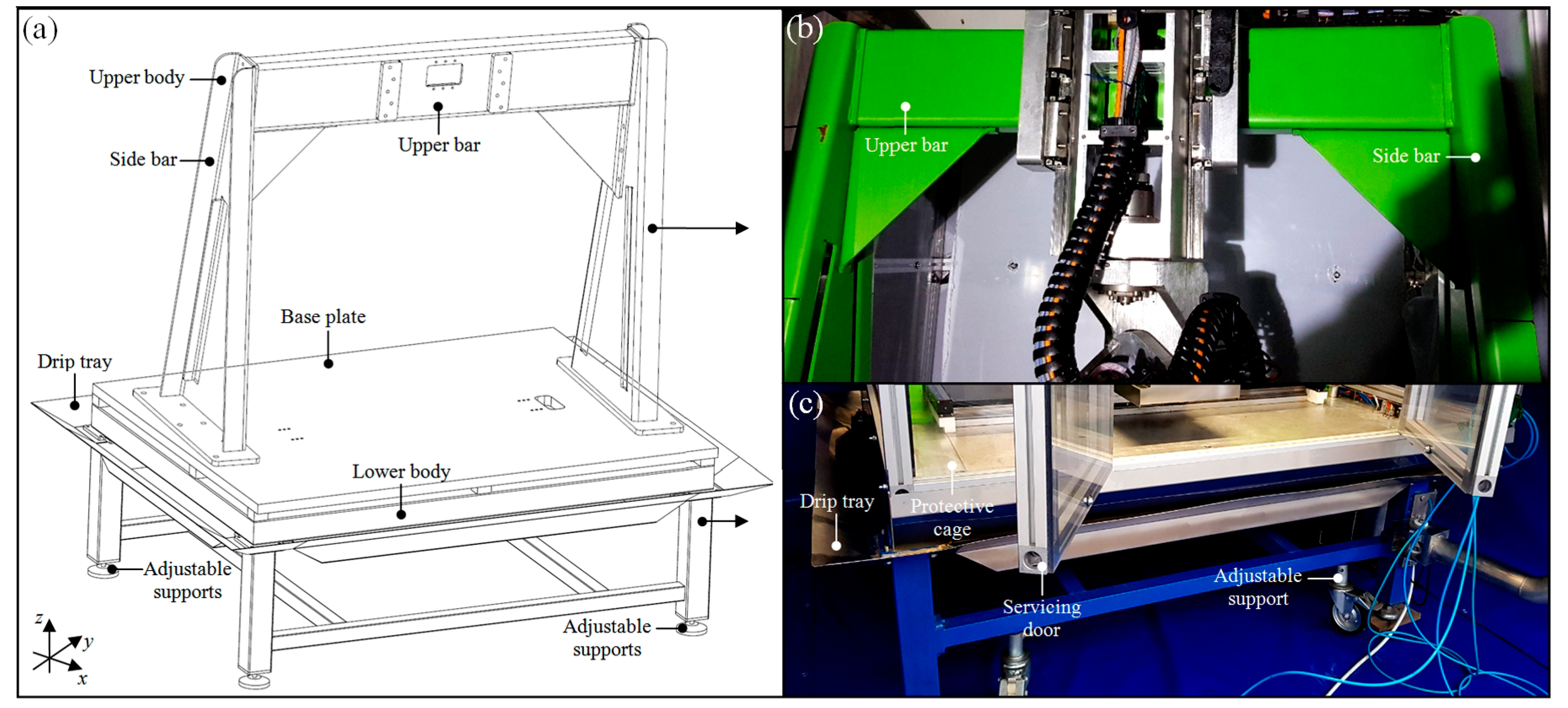
The main element of the 5-axis CNC grinding machine was a high-stiffness lower body, constituting the basis for the whole technological machine. It was made of cold-bent hard-walled profiles in a truss shape with dimensions 120 × 120 × 6 mm which, after the welding process, was subjected to a stress annealed treatment. The bottom part of the lower body was equipped with adjustable supports, enabling the proper leveling of the technological machine. In addition, the body was equipped with a drip tray for efficient collection and discharge of the coolant fed in the grinding process. An intermediate element between the frame and the further parts of the technological machine was an aluminum plate, attached to the bottom part of the frame and constituting the assembly base for subsequent components/units of the machine. The lower body had a structure consisting of two side bars and one upper bar twisted together into one compact whole in the form of a gate, for ensuring high-stiffness during operation. Such a construction, forming the upper body, was an extremely important element of the 5-axis CNC grinding machine, necessary for the correct vertical operation of the Z linear axis and the accompanying B and C rotary axes, respectively. The upper body was produced of high-quality sheet metal with thickness t = 12 mm, shaped in the bending process to obtain a sufficiently high-stiffness and to provide adequate parameters of vibration damping and high thermal resistance. All elements, after the welding process, were annealed in order to eliminate internal stresses, and then machining of the base elements was performed. Additionally, in order to ensure proper work safety, a protective cage made of aluminum profiles and plates made of transparent polycarbonate (PC) with a thickness t = 15 mm was used. In the front part, it was equipped with a servicing door. An axonometric view of the three-dimensional (3D) model of the lower and upper body and detailed views of its construction are presented in Figure 2.
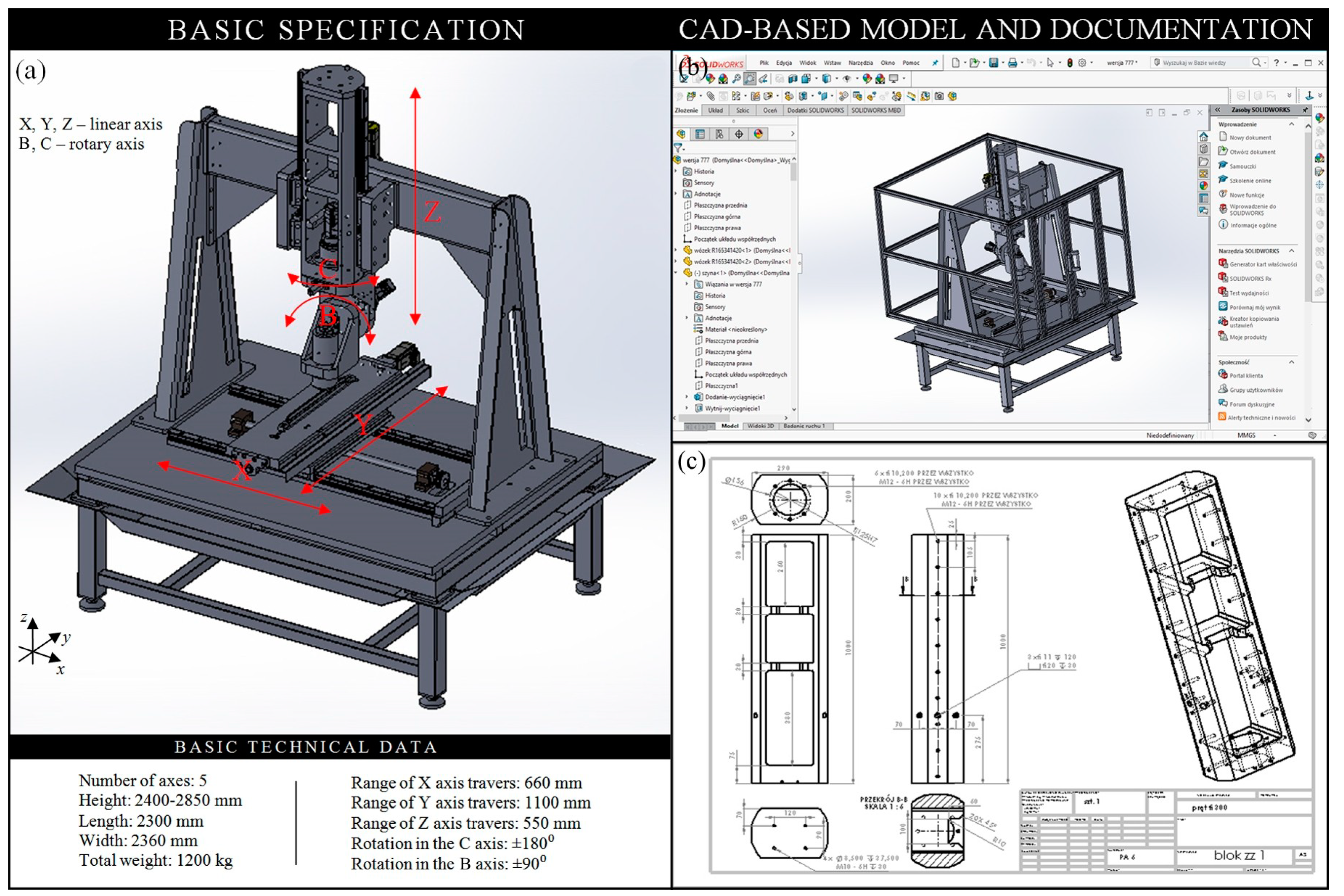
An extremely important role in the described 5-axis CNC grinding machine was played by the vertical auxiliary body of the Z linear axis (travel in the range 0–550 mm). This body created an integral part, together with the remaining bodies of the B and C rotary axes (rotations in the range ±90° and ±180°, respectively). The linear guides were attached to the body, together with the runner blocks. One of the two rotary axes of the technological machine was the C axis. The auxiliary body of the C rotary axis was attached to the auxiliary body of the Z linear axis, forming an integral whole with it. Properly designed reinforcing ribs ensure high structural stiffness. The body of the C axis was the geometric basis for the B axis, which was the second rotary axis of the 5-axis CNC grinding machine, to which the grinding spindle was directly attached. The body of the B rotary axis created a kinetic pair, together with the body of the Z linear axis and the body of the C rotary axis. All the auxiliary bodies were made of high-grade aluminum to obtain the smallest possible mass and adequate high-stiffness. Axonometric views of the 3D models and construction details of the auxiliary body of the Z linear axis, as well as bodies of the C and B rotary axes, are presented in Figure 3.
In the auxiliary body of the B rotary axis, a main drive was installed. In this case, grinding electrospindle type PTShPp-30-36Km120 (FŁT Kraśnik SA, Kraśnik, Poland) was used. When selecting it, the correct speed of the machining being carried out and its control range, as well as process accuracy, were taken into account. In the electrospindle, an asynchronous motor enabling to obtain a range of rotational speeds ns = 3000–30,000 min−1, at a power P = 2.7–3.2 kW and electric voltage U = 153–183 V, was used. Due to the high inrush electric current I = 14 A, for the proper functioning of the electrospindle, a dedicated frequency converter (inverter) providing power Pmin = 7.5 kW was equipped. The exchange of machining tools (various types of small-sized grinding wheels made of CBN abrasive grains) in the electrospindle takes place manually.
The important element of the main drive, necessary to ensure unchangeable operating para- meters and relatively long service life time, was the system for producing and supplying lubrication to the electrospindle bearings in the form of an air–oil aerosol. The UDL-5 EP system (FŁT Kraśnik SA, Kraśnik, Poland) with a low oil level sensor and a pressure transmitter was used, due to its compatibility with the selected electrospindle type. The system was characterized by the following work parameters: Input pressure pin = 0.3–0.7 MPa, output pressure pout = 0.04–0.10 MPa, the range of drops adjustment 20–100 drops/min, the spray tank capacity Q = 500 cm3, and mass m = 3 kg. The cooling agent recommended by the manufacturer was an air–oil aerosol based on Hydrol® L-HL hydraulic oil (PKN Orlen SA, Poland), given in the amount ~20 drops/min, in pressure range p = 0.10–0.12 MPa, and in range of rotational speeds ns = 3500–50,000 min−1. An additional component of the main drive was also the electrospindle cooling system type EP-18-150K (Euro Products, Poznań, Poland), in which the Ergolid® EKO (Boryszew SA, Sochaczew, Poland), a non-freezing fluid, was used. The system provided the efficiency of grinding fluid flow rate QGF = 24 L/min.
In the 5-axis CNC grinding machine, the linear-guide connectors on the three main linear axes X, Y, and Z was used. In accordance with the current trends in the construction of CNC machines, the describing technological machine was equipped with ready-made commercial rolling elements. For all axes, the SNS-type ball rails (size 45 mm, accuracy H) and FNS-type standard flanges runner blocks (size 45 mm, accuracy C1) (Bosh Rexroth AG, Schweinfurt, Germany) were used. These elements guaranteed the expected high positioning accuracy with high linear speed. For the drive of linear guide systems, the appropriate SEM-E-S-type screw–nut pair (Bosh Rexroth AG, Schweinfurt, Germany) was used. The whole was powered by BSM63N-275 AC servo motors (Baldor, ABB group, Zurich, Switzerland), in an intermediate configuration for each axis, respectively. The AC servo motor (TC = 1.47 Nm, I = 1.97 A, ns = 10,000 min−1, m = 2.3 kg) was equipped with a precise positioning system containing an encoder that provided the possibility of feedback, which also allowed to treat it as a measurement-control system.
Important elements of the 5-axis CNC grinding machine construction were also two C and B rotary axes, which ensured precise positioning and, thus, repeatability of results—which is a key issue of obtaining the given machining parameters. For their proper functioning, which is understood as a precise rotation, the bearing blocks embedded in specially designed bushes, which in turn were embedded in the auxiliary bodies of the C and B rotary axes, were responsible. Conical bearings with the appropriate voltage value were used here, which ensured the correct realization of this function. Requirements regarding the accuracy and precision of motion executive elements forced the use of precise reinforced output bearing for the rotary axes drive. For several years, manufacturers have been using them successfully for tilting–turning tables of CNC machines, resulting in highly backlash-free kinematic systems. As in the case of ball rails and flanges runner blocks, also in this case, ready-made commercial components were used. CPU-25A (TA = 108 Nm, TM = 284 Nm, TN = 67 Nm, TR = 157 Nm, nin(max) = 5600 min−1, nav(max) = 3500 min−1) reinforced output bearing (Harmonic Drive AG, Limburg an der Lahn, Germany).
The control and monitoring systems in the 5-axis CNC grinding machine were included elements indirectly involved in controlling the technological machine (control program) and directly controlling the electrical systems (servo amplifiers, frequency converters, contactors, etc.) and measuring elements (encoders in servo motors, limit switches in individual linear and rotary axes, etc.). Because the assumptions took into account the conducting of the machining process in an automated and repeatable manner, it was necessary to use the appropriate software to control the machining parameters (feed, direction, rotational speed, automatic positioning). A control program in the form of G-codes was introduced into the technological machine through the advanced Mach3 ver. R3.043.022 software (Newfangled Solutions LLC, Livermore Falls, ME, USA). The software allowed for control of movement of the X, Y, Z, C, and B axes, operation of the electrospindle, operation of the cooling system of the machining zone and processing parameters. Elements of industrial automation necessary to control the operation of the technological machine were mostly placed in the main control cabinet, including servo amplifiers compatible with servo motors (Baldor, ABB Group), frequency converter (inverter), control card that provides communication between the Mach3 software and the servo amplifiers of individual axes, Windows workstation, and other electrical elements, e.g., contactors, relays, overload protections, and electrical-signal cables.
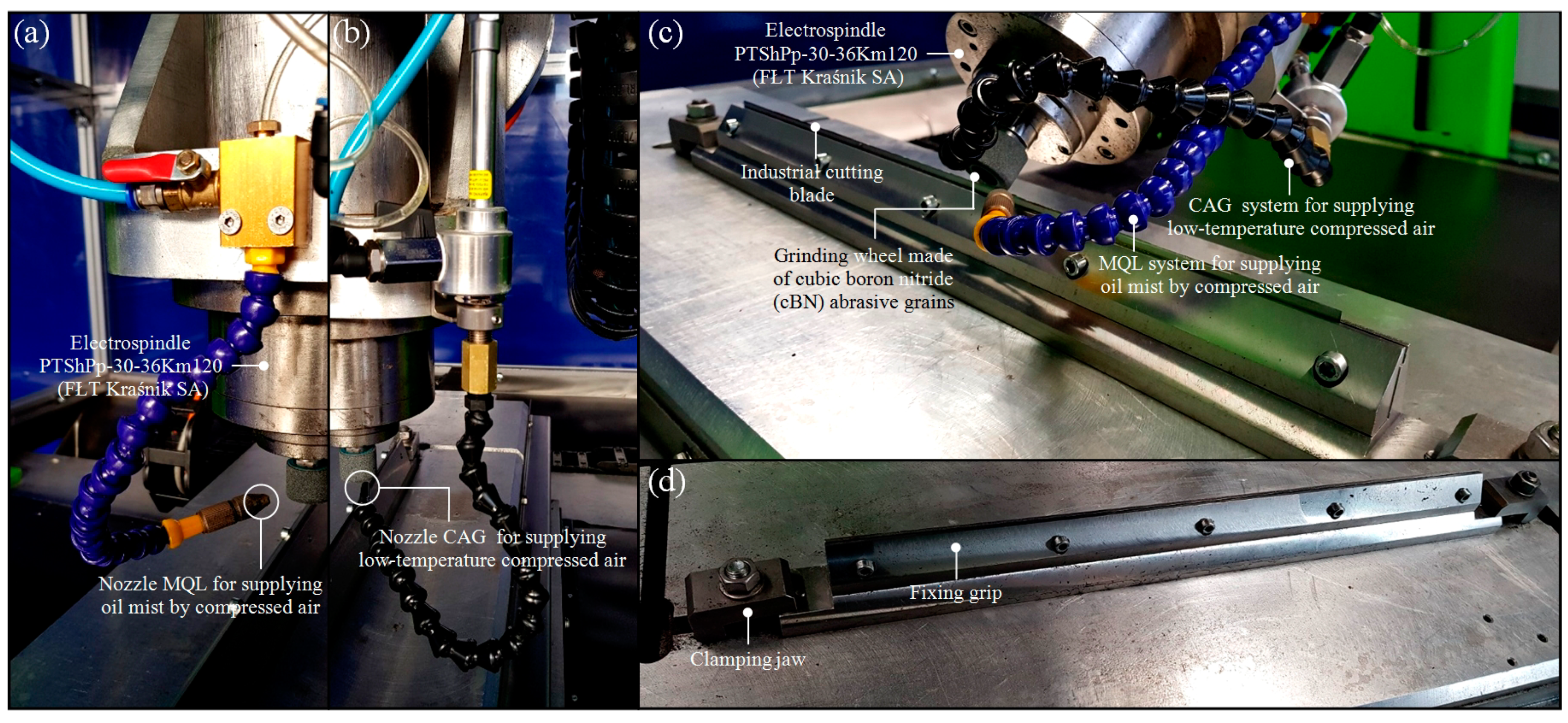
The machine was also equipped with cooling–lubricating systems supporting the grinding process based on the minimum quantity lubrication (MQL) and cold air gun (CAG) methods. Both systems used nozzle MQL for supplying oil mist by compressed air and nozzle CAG for supplying low-temperature compressed air, which were specially designed to ensure that, in addition to the cooling and lubricating function of the machining zone, they also provided effective fluid cleaning and dirt separation. Details of above-mentioned systems are presented in Figure 4a,b.
A properly designed and made fixing grip plays a key role in the regeneration of industrial cutting blades. In this case, repeatability of the process, precision of the workpiece placement, proper stiffness in the whole process, and proper access of the grinding wheel to the workpiece were very important. The grip was based to the technological machine table by clamping jaws, while the workpiece was clamped by means of several clamping screws located on the side of the grip. General and detailed views of the fixing grip are presented in Figure 4c,d, whereas a general view of a complete technological machine and its key systems and elements is presented in Figure 5.

2.3. Testing Phase

After successfully finishing the construction phase, the authors went on to the phase, related to testing the constructed 5-axis CNC grinding machine. The tests included:
  • Checking the correctness of the assembly and making modifications to the configuration of the main and auxiliary bodies, hydraulic and pneumatic systems, manipulation systems X, Y, and Z linear axes, as well as the C and B rotary axes, control systems with the software, systems for the feeding of cooling and lubricating fluid to the grinding zone and fixing grip for the workpiece.
  • Development of a suitable program to carry out machining tasks intended for the process of precision grinding of cutting edges of industrial cutting blades, as well as conducting preliminary precision grinding for determining the correctness of parameter selection during this process.
A set of seven planar cutting tools, used in the ST600VU automatic skinning machine (STEEN F.P.M. International, Kalmthout, Belgium) that works in a technological line for skinning flat fishes (Baltic species of flounder, Platichthys flesus trachurus, and plaice, Platessa platessa baltica, obtained from Danish fisheries), was chosen for the regeneration process. The general view of one of the industrial cutting blades prepared in the machining process is presented in Figure 6, whereas the characteristics of all blades are given in Table 1. Additionally, in Table 2 and Table 3, chemical composition and selected properties of X39CR13 high carbon martensitic stainless steel (material from which the described blades were made) is given.
Before abrasive processing started, all of the low-stiffness planar industrial cutting blades (Kuno Wasser GmbH, Solingen, Germany for Steen F.P.M. International, Kalmthout, Belgium) were properly prepared (degreased and cleaned with compressed air). The precision grinding process was carried out for the following conditions given in Table 4.
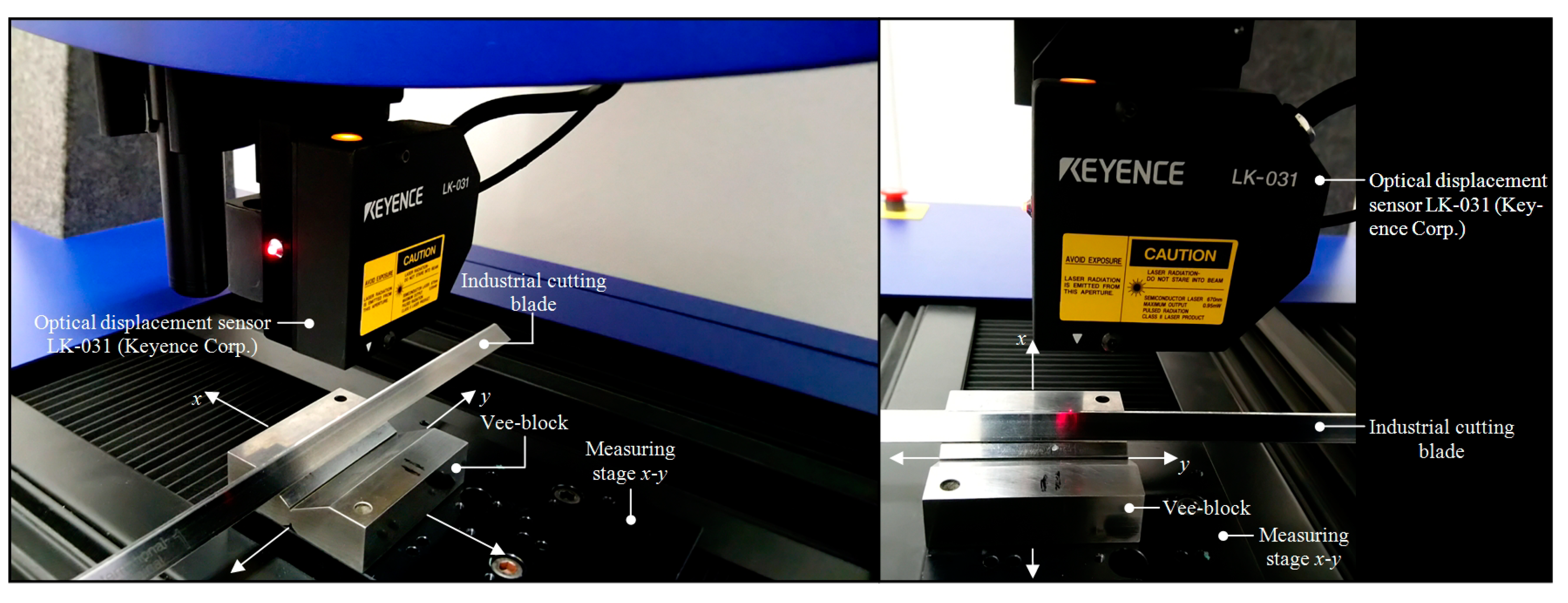
After the end of the abrasive processing, all industrial cutting blades were subjected to high-accuracy 3D optical measurements in order to assess the influence of the preset machining parameters of the expected cutting edge surface texture. In the measurements, a multisensory optical profilometer Talysurf CLI 2000 (Taylor-Hobson Ltd., Leicester, Great Britain) equipped with LK-031 optical displacement sensor (λ = 670 nm, P = 0.95 mW, ds ~ 30 mm, r = 1 µm) and LK-2001 controller (Keyence Corp., Osaka, Japan) was used. Detailed characteristics of this instrument were presented in the work [26], whereas its view during measurements is shown in Figure 7.
The measurements methodology included 1.50 × 1.50 mm measurements of the topographies of the selected surface fragment of each of the industrial cutting blade for conditions given in Table 5. After the measurement, the saved *.SUR file with measurement data was opened in specialized TalyMap Silver ver. 4.1.2 (Digital Surf, Besançon, France) software. Before starting the proper analyses, the measurement data were leveled and (if necessary) non-measured points were filled out. A proper analysis was carried out on the basis of a surface map in indexed colors (where the height of the surface elements was encoded with the color), and topography of measured surface and calculated values of selected parameters from the amplitude, spatial, and hybrid groups is given in Table 6. Additionally, from 1.50 × 1.50 mm surface topography, a fragment, which presented area of cutting blade, was extracted. In this way, a 0.90 × 1.25 mm surface topography was obtained. After filtering out waviness, for such surface topography, the software calculated selected parameters.
Collection of obtained results of measurements are presented in Figure 8, Figure 9 and Figure 10.
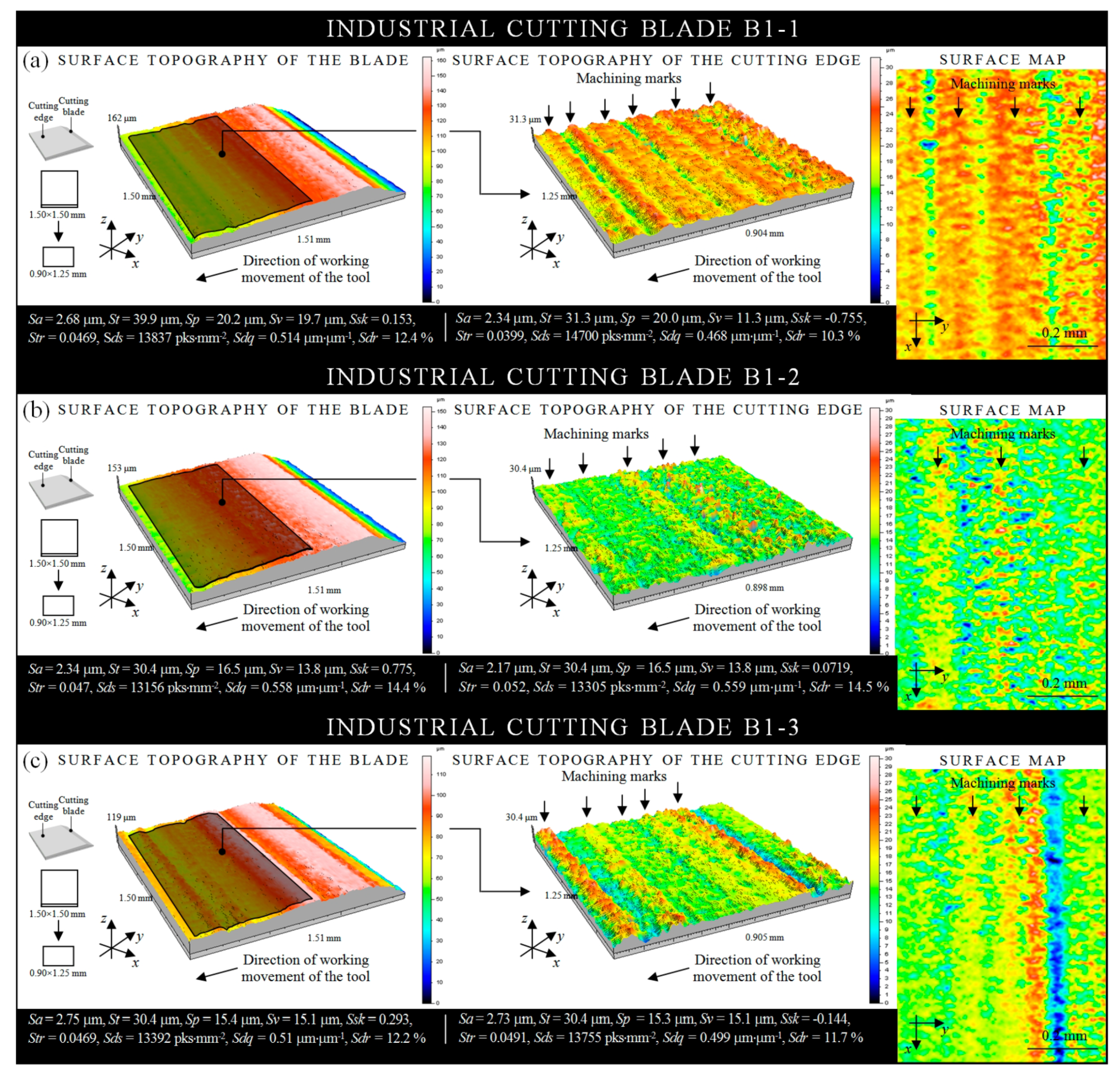
The collection of results of the measurements obtained by the use of multisensory optical profilometer Taylor-Hobson Talysurf CLI 2000 for a surfaces of three low-stiffness planar industrial cutting blades regenerated by the peripheral grinding process (vw = 300–400 mm/min, ns = 38,000 min−1) realized in a 5-axis CNC grinding machine is presented in Figure 8. The analysis of the above results allows to state that for all regenerated surfaces of cutting edges, one can observe clear machining marks characteristic of the grinding process. Marks, perpendicular to the working movement direction of the cutting edges, were shaped more or less regularly with similar spacing. Their height (given by St amplitude parameter) was in a level ~15–16 μm (samples B1-1 and B1-3—Figure 8a,c, respectively) and ~5–6 μm (sample B1-2—
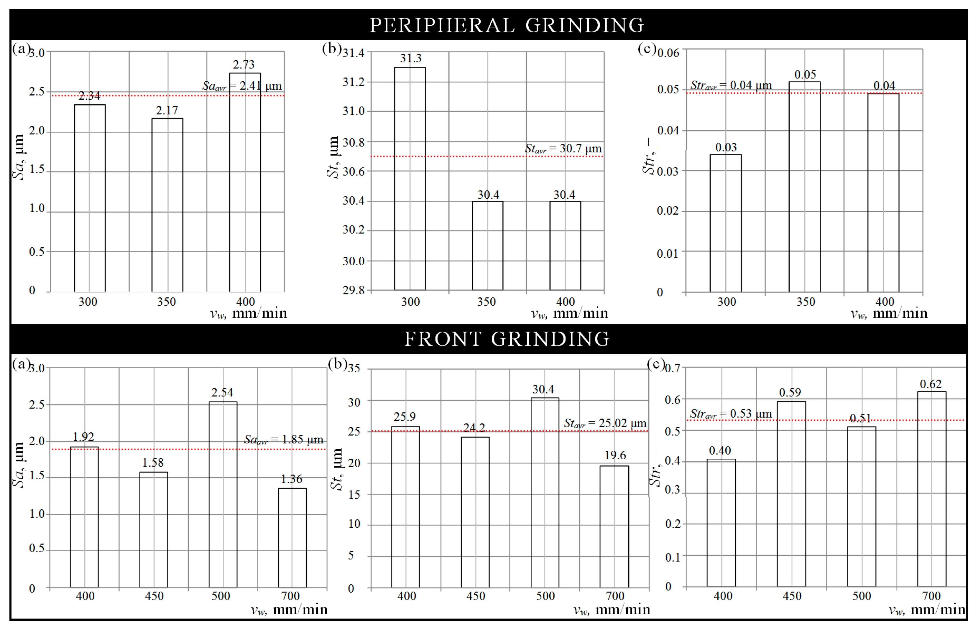
Figure 8b). A comparison of the results of the analyses, presented in graphical form with the values of surface texture parameters, is listed in Figure 10a–c (top). It can be noticed that for the cutting edge of sample B1-2, the lowest values were obtained (Sa = 2.17 μm, St = 30.4 μm, and Str = 0.03 μm). The Sds spatial parameter was also characterized by lower values, whereas for two hybrid parameters (Sdr and Sdq), higher values were obtained. The sign of the Ssk amplitude parameter indicated the predominance of peaks comprising the surface. In regard to the above, the sample B1-2 can be considered as regenerated in the most appropriate way from those presented in Figure 8. Nevertheless, the geometry of the surface has not been fully reproduced correctly, which forced to change the kinematics of the grinding process. Subsequent tests were carried out using front grinding.
The other collection of results of the measurements obtained by the use of multisensory optical profilometer Taylor-Hobson Talysurf CLI 2000 for a surfaces of four low-stiffness planar industrial cutting blades regenerated by the front grinding process (vw = 400–700 mm/min, ns = 38,000 min−1) realized on a 5-axis CNC grinding machine is presented in Figure 9.
The analysis of the above results allows to state that for all regenerated surfaces of the cutting edges, one can observe only machining mark residues. All surfaces were relatively smoother than those obtained in the peripheral grinding process. Their height (given by St amplitude parameter) was in a level ~10 μm (machining mark residues) and ~5 μm (smooth area) in relation to samples B1-4, B1-5, and B1-6 (Figure 9a–c, respectively), as well as in a level ~5–6 μm (machining mark residues) and ~3–4 μm (smooth area) in relation to sample B1-7 (Figure 9d). A comparison of the results of the analyses, presented in graphical form with the values of surface texture parameters, is listed in Figure 10a–c (bottom). It can be noticed that for the cutting edge of sample B1-7, the lowest values were obtained (Sa = 1.26 μm, St = 19.6 μm, and Str = 0.622 μm). The values of the two essential Sa and St amplitude parameters, in this case, were lower by 62.68% and 64.48%, respectively, to values obtained for the cutting edge surface of the most effectively regenerated sample B1-2. The Sds spatial parameter was characterized by higher values, whereas for the two hybrid parameters (Sdr and Sdq), lower values were obtained. As with the sample B1-2, the sign of the Ssk amplitude parameter for sample B1-7 indicated the predominance of peaks comprising the surface. For all the surfaces of the samples presented in Figure 9, the best geometrically-shaped was found to be sample B1-7. It was characterized by a relatively flat surface with low values of the heights of surface irregularities without visible machining marks. In this case, a combination of high workpiece peripheral speed and abrasive tool rotational speed allowed for a satisfactory effect and relatively correct restoration of the surface geometry. Two kinematic variations of the grinding process tested confirmed that front grinding is much more beneficial than peripheral. This type of grinding will be used in subsequent, much more intensive testing that will help to optimize the process parameters and improve, to a greater extent, the geometry of regenerated cutting edge surfaces of industrial cutting blades.

3. Conclusions

On the basis of the entire scope of works related to the development of the precision grinding process for industrial cutting blades used in cutting of soft tissues by a prototype 5-axis CNC grinding machine, the following conclusions can be drawn:
  • In fish skinning, the replacement of cutting blades in automatic skinning machines is often needed, especially during intensive technological processes. A relatively short time of efficient work of the blades (caused by formation of corrosive interactions, resulting from a working environment and rapid mechanical wear) is the main source of production stoppages, necessary for its exchanging. This involves considerable financial losses, which is a strongly undesirable action in any sort of a fish processing plant. Good industrial practice requires the solving of this problem.
  • One of the proposals, presented in this work, is the possibility of full renewal of the cutting ability of the industrial cutting blade in the precision grinding process. In this case, the authors designed and constructed a 5-axis CNC grinding machine. The conceptual works, main assumptions, and design phase realized in Solid Works 2017 (Section 2.1) led to the development of a prototype of a technological machine (Section 2.2).
  • The technological machine, after checking the correctness of the assembly and making modifications to the configuration of its component and functional units, was used in the preliminary testing program related to the renewal of the cutting ability of the cutting edges of industrial cutting blades (Section 2.3).
  • A successful course of the preliminary testing program allowed to state that the constructed technological machine fulfilled its function, and its usefulness in the described application was significant. The correct functioning of all components/units and the correctness of the precision grinding process were also confirmed. Test results, in relation to the correct restoration of the cutting edge surface geometry (shape and correctness surface texture) of industrial cutting blades, turned out to be very promising. The most beneficial results were obtained in the precision front grinding process (vw = 700 mm/min, ns = 38,000 min−1) (Section 2.3).
  • Verification of the correctness of the precision grinding process, in relation to obtained cutting edge shape and its surface texture, was carried out by optical measurements. In this case, a multisensory optical profilometer Talysurf CLI 2000 was used (Figure 7). Obtained results confirmed that the most effective surface parameters were obtained for the precision front grinding process (Figure 9 and Figure 10).
  • In general, very satisfactory and promising results induce the authors to continue this subject matter. In the future, they will focus, inter alia, on further optimization of process parameters and application of cooling–lubricating systems supporting the grinding process based on the minimum quantity lubrication (MQL) and cold air gun (CAG) methods.

Author Contributions

Supervision, W.K.; conceptualization, B.Z., K.N., W.K. and M.S.; research methodology, B.Z. and K.N.; funding acquisition and resources, B.Z.; investigations, B.Z., K.N. and M.S.; formal analysis, B.Z., W.K., K.N. and M.S.; writing—original draft preparation, W.K.; writing—review and editing, W.K. and K.N.

Funding

This research received no external funding.

Conflicts of Interest

The authors declare no conflicts of interest.

Nomenclature

CADComputer Aided Design
CAGCold Air Gun
CBNCubic Boron Nitride
CMMCoordinate Measuring Machine
CNCComputerized Numerical Control
CrNChromium Nitride
CVDChemical Vapour Deposition
DLCDiamond-Like Coating
EMOExposition Mondiale de la Machine-Outil
GFGrinding Fluid
MQLMinimum Quantity Lubrication
PCPolycarbonate
PSDPlasma Sharpened Diamond
PVDPhysical Vapor Deposition
TiAlNTitanium Aluminium-Nitride
TiCTitanium Carbide
TiCNTitanium Carbo-Nitride
TiNTitanium Nitride
ZrNZirconium Nitride
adDressing allowance, mm
aeWorking engagement (machining allowance), mm
dsLaser spot diameter, mm
idNumber of dressing passes, –
mMass, kg
nsRotational speed, min−1
nsdRotational speed (dressing), min−1
nin(max)Maximum input rotational speed, min−1
nav(max)Average input rotational speed, min−1
pinInput pressure, MPa
poutOutput pressure, MPa
rResolution, μm
tThickness, mm
tg totTotal grinding time, s
vfdTable feed speed while dressing, mm/s
vsGrinding wheel peripheral speed, m/s
vwWorkpiece peripheral speed, mm/min
IElectric current, A
PPower, kW
QCapacity, cm3
QGFGrinding fluid flow rate, ml/h
QdDiamond dresser mass, kt
SaArithmetic mean deviation of the surface, µm
SdrDeveloped interfacial area ratio, %
SdsDensity of summits of the surface, pks/mm2
SdqRoot-mean-square slope of the surface, μm⋅μm−1
SpMaximum height of summits, µm
SskSkewness of the height distribution, –
StTotal height of the surface, µm
StrTexture aspect ratio of the surface, –
SvMaximum depth of valleys, µm
TAAverage torque, Nm
TCContinuous torque, Nm
TMMomentary peak torque, Nm
TNRated torque, Nm
TRRepeated peak torque, Nm
UElectric voltage, V

Appendix A

Table A1. Selected major manufacturers of industrial cutting blades for regular and deep skinning.
ProducerMaterialCoatingsCompatibility with Skinning Machines
Kyocera Unimerco Tooling A/S, Sunds, DenmarkStainless steel Baader, Nock, Grasselli, Carnitech, Varlet
Kuno Wasser GmbH, Solingen, GermanyStainless steel Cretel, Dimapel/Varlet, F.P.M. International/Steen, Foodlogistik, Grasselli, Maja, Nematec, Nock, Townsend, Weber
Lumbeck & Wolter GmbH & Co. KG, Wuppertal, GermanyStainless steel Maja, Weber, Townsend, Nematec, Nock, Steen, Varlet, Cretel, Grasselli
LUTZ GmbH & Co. KG, Solingen, GermanyStainless steelTiN, TiC, TiCN, TiAlN, ZrN, DLC, CrN, Teflon® Grasselli, Maja, Weber, Cretel, Steen, Nock, Townsend
BE Maschinenmesser GmbH & Co. KG, Spreenhagen, GermanyStainless steel Maja, Weber, Grasselli, Cretel
Markus Heucher, Duisburg, GermanySandvik 13C26 stainless steel Nock, Weber, Maja
Cutting Edge Services Ltd., Chorley, Great BritainStainless steel Grasselli
Jewel Blade Ltd., Sheffield, Great BritainStainless steel Various types
Jarvis Industries Canada Ltd., Calgary, CanadaHighly polished surgical grade stainless steel Cretel, Grasselli, Maja, Townsend, Varlet, Weber
American Cutting Edge, Miamisburg, OH, USAHighly polished cryogenically hardened stainless steelTiN, TiAlN, TiC, Teflon®Townsend, Maja, Meyn, Grasselli, Weber, Best & Donovan, Varlet, Cretel
PrimeEdge, Inc., Elk Grove Village, IL, USAStainless steel Cretel, Grasselli, Laint, Maja, Foodlogistik, Nematec, Nock, Paulos, Townsend, Varlet, Weber
Carnotex SA DE CV Hermosillo, MexicoStainless steel Dadaux, Cretel, Nock, Weber, Maja, Townsend, Grasselli
Courier Sharpening Ltd., Te Awamutu, New ZealandPolished premium grade stainless steel Townsend, Grasselli, Maja, Weber, Baader

References

  1. Soetaert, M.; Decostere, A.; Polet, H.; Verschueren, B.; Chiers, K. Electrotrawling: A promising alternative fishing technique warranting further exploration. Fish Fish. 2015, 16, 104–124. [Google Scholar] [CrossRef]
  2. Fujii, H.; Sakakura, Y.; Hagiwara, A.; Bostock, J.; Soyano, K.; Matsushita, Y. Research and development strategy for fishery technology innovation for sustainable fishery resource management in North-East Asia. Sustainability 2017, 10, 59. [Google Scholar] [CrossRef]
  3. Chavanne, H.; Janssen, K.; Hofherr, J.; Contini, F.; Haffray, P.; Aquatrace Consortium; Komen, H.; Nielsen, E.E.; Bargelloni, L. A comprehensive survey on selective breeding programs and seed market in the European aquaculture fish industry. Aquacult. Int. 2016, 24, 1287–1307. [Google Scholar] [CrossRef]
  4. Truong, B.Q.; Buckow, R.; Stathopoulos, C.E.; Nguyen, M.H. Advances in high-pressure processing of fish muscles. Food Eng. Rev. 2015, 7, 109–129. [Google Scholar] [CrossRef]
  5. Okpala, C.O.R. Fish Processing by Ozone Treatment-Is Further Investigation of Domestic Applications Needful? Chem. Eng. Trans. 2017, 57, 1813–1818. [Google Scholar]
  6. Cheng, J.H.; Sun, D.W.; Zeng, X.A.; Liu, D. Recent advances in methods and techniques for freshness quality determination and evaluation of fish and fish fillets: A review. Crit. Rev. Food Sci. Nutr. 2015, 55, 1012–1225. [Google Scholar] [CrossRef]
  7. Nagarajarao, R.C. Recent advances in processing and packaging of fishery products: A review. Aquat. Procedia 2016, 7, 201–213. [Google Scholar] [CrossRef]
  8. Dutta, M.K.; Issac, A.; Minhas, N.; Sarkar, B. Image processing based method to assess fish quality and freshness. J. Food Eng. 2016, 177, 50–58. [Google Scholar] [CrossRef]
  9. Sampels, S. The effects of processing technologies and preparation on the final quality of fish products. Trends Food Sci. Technol. 2015, 44, 131–146. [Google Scholar] [CrossRef]
  10. Bar, E.S. A case study of obstacles and enablers for green innovation within the fish processing equipment industry. J. Clean. Prod. 2015, 90, 234–243. [Google Scholar]
  11. Vidaček, S.; Soro, R. Clean fish processing technologies. In Trends in Fish Processing Technologies; Borda, D., Nicolau, A.I., Raspor, P., Eds.; CRC Press: Boca Raton, FL, USA, 2017; pp. 171–186. [Google Scholar]
  12. Chandra, K.; Kain, V.; Srinivasan, N.; Samajdar, I.; Balasubrahmanian, A.K. Temper embrittlement and corrosion behaviour of martensitic stainless steel 420. Adv. Mater. Res. 2013, 794, 757–765. [Google Scholar]
  13. Bradbury, S.R.; Huyanan, T. Challenges facing surface engineering technologies in the cutting tool industry. Vacuum 2000, 56, 173–177. [Google Scholar] [CrossRef]
  14. Pini, S.; Groppetti, R.; Mucchino, C.; Geretto, V. Evaluation of DLC, WC/C, and TiN coatings on martensitic stainless steel and yttria-stabilized tetragonal zirconia polycrystal substrates for reusable surgical scalpels. ISRN Ceramics 2013, 2013, 237175. [Google Scholar] [CrossRef]
  15. Xing, Y.; Deng, J.; Li, S.; Yue, H.; Meng, R.; Gao, P. Cutting performance and wear characteristics of Al2O3/TiC ceramic cutting tools with WS2/Zr soft-coatings and nano-textures in dry cutting. Wear 2014, 318, 12–26. [Google Scholar] [CrossRef]
  16. Talib, R.J.; Zaharah, A.M.; Selamat, M.A.; Mahaidin, A.A.; Fazira, M.F. Friction and wear characteristics of WC and TiCN-coated insert in turning carbon steel workpiece. Procedia Eng. 2013, 68, 716–722. [Google Scholar] [CrossRef]
  17. Guo, Y.D. Wear rule of TiAlN coated cutting tool when milling material with high hardness at high speed. Key Eng. Mater. 2011, 458, 106–112. [Google Scholar]
  18. Kuleshov, A.K.; Uglov, V.V.; Rusalsky, D.P.; Grishkevich, A.A.; Chayeuski, V.V.; Haranin, V.N. Effect of ZrN and Mo-N coatings and sulfacyanization on wear of wood-cutting knives. J. Frict. Wear 2014, 35, 201–209. [Google Scholar] [CrossRef]
  19. Flöter, A.; Gluche, P.; Bruehne, K.; Fecht, H.J. Diamond coat hones the cutting edge. Met. Powder Rep. 2007, 62, 16–20. [Google Scholar] [CrossRef]
  20. Bewilogua, K.; Hofmann, D. History of diamond-like carbon films—From first experiments to worldwide applications. Surf. Coat. Tech. 2014, 242, 214–225. [Google Scholar] [CrossRef]
  21. Vetter, J. 60 years of DLC coatings: Historical highlights and technical review of cathodic arc processes to synthesize various DLC types, and their evolution for industrial applications. Surf. Coat. Tech. 2014, 257, 213–240. [Google Scholar] [CrossRef]
  22. González, H.; Calleja, A.; Pereira, O.; Ortega, N.; de López Lacalle, N.L.; Barton, M. Super abrasive machining of integral rotary components using grinding flank tools. Metals 2018, 8, 24. [Google Scholar] [CrossRef]
  23. Álvarez, Á.; Calleja, A.; Ortega, N.; de López Lacalle, N.L. Five-axis milling of large spiral bevel gears: Toolpath definition, finishing, and shape errors. Metals 2018, 8, 353. [Google Scholar] [CrossRef]
  24. Calleja, A.; Bo, P.; González, H.; Barton, M.; de López Lacalle, N.L. Highly accurate 5-axis flank CNC machining with conical tools. Int. J. Adv. Manuf. Tech. 2018, 97, 1605–1615. [Google Scholar] [CrossRef] [Green Version]
  25. European Committee for Standardization-European Committee for Electrotechnical Standardization. Stainless Steels—Part 1: List of Stainless Steels; Technical Report No. EN 10088-1: 2014; CEN-CENELEC Management Centre: Brussels, Belgium, 2014. [Google Scholar]
  26. Kapłonek, W.; Sutowska, M.; Ungureanu, M.; Çetinkaya, K. Optical profilometer with confocal chromatic sensor for high-accuracy 3D measurements of the uncirculated and circulated coins. J. Mech. Energy Eng. 2018, 2, 181–192. [Google Scholar] [CrossRef] [Green Version]
  27. International Organization for Standardization. Geometrical Product Specification (GPS)—Surface Texture: Areal—Part. 2: Terms, Definitions and Surface Texture Parameters; Technical Report No. 25178-2:2012; International Organization for Standardization: Geneva, Switzerland, 2012. [Google Scholar]
  28. Stout, K.J.; Liam, B.; Dong, W.; Mainsah, E.; Luo, N.; Mathia, T.; Sullivan, P.; Zahouani, H. The Development of Methods for the Characterization of Roughness in Three Dimensions; Technical Report No. EUR 15178 EN; BCR: Brussels, Belgium, 1993. [Google Scholar]
Figure 1. Design phase of a 5-axis CNC grinding machine for the precision grinding process of the cutting edges of industrial cutting blades: (a) Computer model of the CNC technological machine with kinematics of individual axes; (b) CAD-based model developed in a Solid Works environment; (c) an example of an executive drawing of the technological machine body.
Applsci 09 03883 g001
Figure 2. Construction phase of a 5-axis CNC grinding machine for the precision grinding process of the cutting edges of industrial cutting blades: (a) Axonometric view of the three-dimensional (3D) model of the upper and lower body; (b) the upper body with mounted auxiliary bodies; (c) construction details of the lower body.
Applsci 09 03883 g002
Figure 3. Construction phase of a 5-axis CNC grinding machine for the precision grinding process of the cutting edges of industrial cutting blades: (a,b) Auxiliary body of the Z linear axis (axonometric view of the 3D model and construction details); (c,d) auxiliary bodies of the C and B rotary axes, respectively (axonometric views of the 3D models and construction details); (e) details of AC servo motor BSM80N-275 AF mounting in of the Z linear axis; (f) details of AC servo motor BSM63N-275 AA mounting in of the B rotary axis.
Applsci 09 03883 g003
Figure 4. Construction phase of a 5-axis CNC grinding machine for the precision grinding process of the cutting edges of industrial cutting blades: (a) Cooling–lubricating system based on the minimum quantity lubrication (MQL) method, using nozzle MQL for supplying oil mist by compressed air; (b) cooling–lubricating system based on the cold air gun (CAG) method, using nozzle CAG for supplying low-temperature compressed air; (c) fixing grip with mounted industrial cutting blade during regeneration process; (d) details of fixing grip.
Applsci 09 03883 g004
Figure 5. Construction phase of a 5-axis CNC grinding machine for the precision grinding process of the cutting edges of industrial cutting blades: (a) General view of a complete technological machine; (b) general view of the upper body and auxiliary bodies of the Z linear axis, as well as the C and B rotary axes inside the protective cage; (c,d) detailed view of the auxiliary bodies of the Z linear axis, as well as the C and B rotary axes, with electrospindle, cooling–lubricating system, and fixing grip with mounted industrial cutting blade.
Applsci 09 03883 g005
Figure 6. General view of a low-stiffness planar industrial cutting blade.
Applsci 09 03883 g006
Figure 7. Multisensory optical profilometer Taylor-Hobson Talysurf CLI 2000 during measurements of low-stiffness planar industrial cutting blade (sample B1-7).
Applsci 09 03883 g007
Figure 8. Collection of results of the measurements obtained by the use of multisensory optical profilometer Taylor-Hobson Talysurf CLI 2000 for surfaces of low-stiffness planar industrial cutting blades regenerated by the precision grinding process (peripheral grinding) realized in a 5-axis CNC grinding machine: (a) Sample B1-1 (vw = 300 mm/min, ns = 38,000 min−1); (b) sample B1-2 (vw = 350 mm/min, ns = 38,000 min−1); (c) sample B1-3 (vw = 400 mm/min, ns = 38,000 min−1).
Applsci 09 03883 g008
Figure 9. Collection of results of measurements obtained by the use of multisensory optical profilometer Taylor-Hobson Talysurf CLI 2000 for surfaces of low-stiffness planar industrial cutting blades regenerated by the precision grinding process (front grinding) realized in a 5-axis CNC grinding machine: (a) Sample B1-4 (vw = 400 mm/min, ns = 38,000 min−1); (b) sample B1-5 (vw = 450 mm/min, ns = 38,000 min−1); (c) sample B1-6 (vw = 500 mm/min, ns = 38,000 min−1); (d) sample B1-7 (vw = 700 mm/min, ns = 38,000 min−1).
Applsci 09 03883 g009
Figure 10. Collection of results in the form of bar graphs, representing values of essential surface texture parameters calculated in TalyMap Silver ver. 4.1.2 software, for the cutting edges of industrial cutting blades regenerated by the use of a 5-axis CNC grinding machine in a peripheral grinding process (top): (a) Sa; (b) St; (c) Str, and front grinding process (bottom): (a) Sa; (b) St; (c) Str.
Applsci 09 03883 g010
Table 1. Characteristics of the industrial cutting blades used in the tests.
No.SampleGeometry 1Hardness 2
DesignationLength, mmWidth, mmThickness, mmVickersRockwell
HVHRC
1.B1-1459.7912.330.60737.00>61.70
2.B1-2459.4912.330.60743.00>61.80
3.B1-3459.4612.300.60741.00>61.20
4.B1-4459.5012.310.60750.00>62.50
5.B1-5459.8012.300.60730.00>61.40
6.B1-6459.6512.310.60737.00>61.70
7.B1-7459.1512.320.60737.00>61.70
1 Measured by bench-type multisensor CMM Video-Check® -IP 250 (Werth Messtechnik GmbH, Löberschütz, Germany); 2 Measured by portable Vickers hardness tester HPO 10 (WPM, Leipzig, Germany).
Table 2. Chemical composition of X39CR13 high carbon martensitic stainless steel.
Element 1FeCSiMnPSCr
Weight, %83.00–87.100.36–0.421.001.000.040.01512.5–14.5
Deviation±0.02±0.02+0.05+0.03+0.005+0.003±0.15
1 According with EN 10088-1: 2014 [25].
Table 3. Selected properties of X39CR13 high carbon martensitic stainless steel.
CountryEUUSAGermanyFranceEnglandItalyChinaPoland
StandardEN-DIN,WNrAFNORBSUNIGBPN
DesignationX39Cr13420X39Cr13Z40C13X39Cr13X40Cr144C134H13
General properties
Corrosion resistanceMechanical propertiesForgeabilityWeldability
averagevery goodgoodwith care
Physical properties
Thermal expansionModulus of elasticityPoisson numberElectrical resistivityElectrical conductivitySpecific heatDensityThermal conductivity
10−6∙K−1GPavΩ∙mm2/mS∙m/mm2J/(Kg∙K)Kg/dm3W/(m∙k)
10.5215~0.27–0.300.551.824607.7030
Processing properties
Automated machiningMachinableMagneticHammer and die forgingCold formingElectrical conductivity
yesyesyesyesnono
Table 4. General characteristics of machining conditions.
Grinding processTraverse surface grinding
Grinding machine5-axis CNC grinding machine
Grinding wheel5A1 28 × 20 × 10/15 ×14 B126 V180 SV (Inter-Diament, Grodzisk Mazowiecki, Poland)
Grinding wheel dressing parametersDresser: Single grain diamond dresser type M 1010 with mass of crystal Qd = 0.75 ct (Inter-Diament, Grodzisk Mazowiecki, Poland), grinding wheel rotational speed while dressing: nsd = 10,000 min−1, dressing allowance: ad = 0.0125 mm, table feed speed while dressing: vfd = 10 mm/s, number of dressing passes: id = 6
Grinding parametersGrinding wheel peripheral speed: vs = 55.7 m/s, grinding wheel rotational speed: ns = 38,000 min−1, working engagement (machining allowance): ae = 0.05 mm, workpiece peripheral speed: vw = 300–700 min−1, total grinding time: tg tot = 210 s
WorkpiecesWorking surfaces of low-stiffness planar industrial cutting blades
GF delivery methodWater aerosol delivered by a single spray nozzle
GF working pressureSupply air pressure: p = 0.8 MPa
GF type5% water solution of Syntilo RHS oil (Castrol Ltd., Liverpool, Great Britain)
GF flow rateQGF = 1050 mL/h
NoSample designationWorkpiece peripheral speed, mm/minRotational speed, min−1Grinding
1.B1-130038,000Peripheral grinding
2.B1-2350
3.B1-3400
4.B1-4400Front grinding
5.B1-5450
6.B1-6500
7.B1-7700
Table 5. General characteristics of measurement conditions.
ParameterSurface Topography of Industrial Cutting BladeSurface Topography of Cutting Edge 1
ValueUnitValueUnit
Area of a single topography (axes x, y, z)1.50 × 1.50 × x.xx 2 mm0.90 × 1.25 × x.xx 3mm
The number of profile points (axis x) 30012349
Distance between profile points (axis x) 0.5 μm0.384
The number of profiles (axis y)301251
Distance between profile points (axis y)5 μm5 μm
Vertical resolution (axis z)x.xx 2 μmx.xx 3 μm
Measurement time1773 s
1 Filtering process: Filter type: Gaussian, surface size: 1.15 × 1.50 mm (3001 × 301 points), standard cut-off: 0.25 mm, filter size: 0.25 × 0.25 mm (652 × 51 points); 2 Values of vertical resolution (axis z): B1-1: 0.163 mm, B1-2: 0.153 mm, B1-3: 0.119 mm, B1-4: 0.184 mm, B1-5: 0.197 mm, B1-6: 0.187 mm, B1-7: 0.211 mm; 3 Values of vertical resolution (axis z): B1-1: 0.031 mm, B1-2: 0.030 mm, B1-3: 0.030 mm, B1-4: 0.025 mm, B1-5: 0.024 mm, B1-6: 0.030 mm, B1-7: 0.019 mm.
Table 6. Surface texture parameters used for characterization of regenerated industrial cutting blades during the precision grinding process realized in a 5-axis CNC grinding machine.
GroupParameterUnitDescriptionImportanceIOPCMS
Amplitude 1SaμmArithmetic mean deviation of the surfaceEssentialYesYes
StμmTotal height of the surfaceEssentialYesYes
SpμmMaximum height of summitsAdditionalYes
SvμmMaximum depth of valleysAdditionalYes
SskSkewness of the height distributionAdditionalYes
Spatial 1StrTexture aspect ratio of the surfaceEssentialYesYes
Sdspks/mm2Density of summits of the surfaceAdditional
Hybrid 1Sdqμm⋅μm−1Root-mean-square slope of the surfaceAdditionalNo
Sdr%Developed interfacial area ratioAdditional
1 Parameters are included in the ISO 25178-2:2012 standard [27] and EUR 15178 EN report [28]; IOP: Influence on the operational properties; CMS: Control possibility in the manufacturing process.

